

Abstract
Recent observations of flagellar counterbend in sea urchin sperm show that the mechanical induction of curvature in one part of a passive flagellum induces a compensatory countercurvature elsewhere. This apparent paradoxical effect cannot be explained using the standard elastic rod theory of Euler and Bernoulli, or even the more general Cosserat theory of rods. Here, we develop a geometrically exact mechanical model to describe the statics of microtubule bundles that is capable of predicting the curvature reversal events observed in eukaryotic flagella. This is achieved by allowing the interaction of deformations in different material directions, by accounting not only for structural bending, but also for the elastic forces originating from the internal cross-linking mechanics. Large-amplitude static configurations can be described analytically, and an excellent match between the model and the observed counterbend deformation was found. This allowed a simultaneous estimation of multiple sperm flagellum material parameters, namely the cross-linking sliding resistance, the bending stiffness, and the sperm head junction compliance ratio. We further show that small variations on the empirical conditions may induce discrepancies for the evaluation of the flagellar material quantities, so that caution is required when interpreting experiments. Finally, our analysis demonstrates that the counterbend emerges as a fundamental property of sliding resistance in cross-linked filamentous polymer bundles, which also suggests that cross-linking proteins may contribute to the regulation of the flagellar waveform in swimming sperm via counterbend mechanics.
Keywords: bending rigidity, shearability, Euler-elastica buckling, static postbuckled deformations
The mechanical properties of semiflexible bundles of filamentous polymers play a diverse and complex role in biology. They are responsible for multiple architectural constraints in a broad range of biological structures, ranging from cytoskeletal shape in eukaryotic cells to cellular division and locomotion, via structures such as flagella and cilia (1, 2). These bundles of filamentous polymers are commonly formed by an assembly of semiflexible filaments interconnected by cross-linking proteins in an array of intricate arrangements (3–6), varying from a rectangular distribution of filaments, for F-actin bundles, to cylindrical structures, as observed in flagellar axonemes (1, 2, 7). A fundamental challenge, both experimentally and theoretically, is to understand how this complex microscopic 3D architecture yields bulk material properties and overall cellular level mechanical responses and, ultimately, function.
Despite the inherent complexity associated with the internal structure of biological filament bundles, the textbook elastic bending stiffness (1, 2, 3, 8–14) has been estimated by using a linear relation between bending moment and curvature (15, 16), as derived from Euler–Bernoulli rod theory. A ubiquitous example is the bending stiffness measurements of sperm flagella from different species (1, 2, 8–12). However, the inadequacy of this theory emerges for complex biological structures via paradoxical empirical responses, as illustrated by experiments first conducted by Lindemann and co-workers (11, 12), where sperm flagella with disabled molecular motors were pinned at the cell body and subject to an effective point force further down the flagellum. In contrast to a classical Euler–Bernoulli filament, the flagella were observed to reverse their curvature beyond the forcing point: the “counterbend” phenomenon (11, 12), as illustrated in Fig. 1 for a sea urchin sperm flagellum, which is simply composed of a canonical axoneme. Indeed, flagellar structures are well known for their ability to shear, in addition to bend, effectively coupling the elastic bending with shearing displacements and modifying the resulting mechanical response (11, 12, 17–19). Interestingly, pure shearing mechanics from Timoshenko beam theory; Cosserat rod theory (15, 16); or, more generally, any local beam theory cannot explain the counterbend in eukaryotic flagella (11, 12). Despite the intrinsic geometrical coupling between shearing and bending deformations present in shearable filaments, no change in curvature can be transmitted, nonlocally along distal sections that are absent from contact forces and moments, because they are locally related to the strain (15, 16). This inconsistency with the counterbend phenomenon entails that shearing effects in cross-linked filament bundles are fundamentally different from the traditional shearing mechanics of Timoshenko and Cosserat, whereas the adequacy of alternative nonlocal engineering theories to study interfilament shearing of filament bundles in biology is still a matter of debate.
Fig. 1.
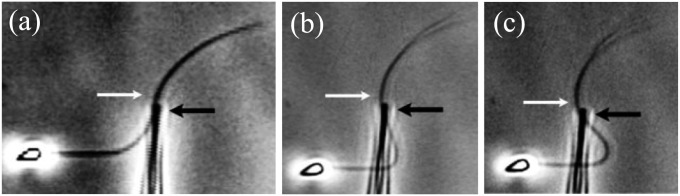
Counterbend (white arrows) during experiments assessing passive sea urchin sperm flagellum bending (12). The black arrows depict the direction of the micromanipulator movement in the sequence, A–C. Micrographs adapted from Pelle et al. (12) with permission from John Wiley and Sons, © Wiley-Liss Inc.
The resolution of this apparent paradox necessitates that flagella cannot be simply modeled as inextensible, unshearable, elastic beams or as general shearable rods (15, 16). Even the simplest flagellum is complex, with nine concentrical microtubule doublets and a central pair, interconnected by radial spokes and nexin bridges (7). Even though each individual microtubule doublet may be approximated as an inextensible filament, flagellar bending induces nonlocal sliding between the microtubule structures, together with strain among the elastic connectors (7, 18). Further complexity comes with conflicting evidence concerning whether the connectors also detach at larger strains (11, 20), in addition to the mechanical influence of the anchoring piece between the axoneme and the rest of the cell via the centriole (7). Altogether, our knowledge of the microscopic structure of flagella and their macroscopic mechanical response clearly indicates the inadequacy of classical rod theories to describe this system (1, 2, 8, 10), from Euler–Bernoulli to Timoshenko and Cosserat (15, 16), whereas their inability to estimate material quantities accurately from experiments highlights the current need to reassess established measurements of the material quantities of passive flagella (1, 2, 8, 10).
Apart from the work by Pelle et al. (11) on counterbend configurations of sea urchin sperm flagella, there is no theoretical study on the resulting passive material response of flagella, in the absence of molecular motor activity, with the cross-linking proteins of flagellar axonemes and flagellar basal compliance. Furthermore, there has been no mathematical demonstration to date of the flagellar counterbend phenomenon, whereas studies on the static, postbuckled configurations of the axoneme induced by external forces, or even on how to measure the resulting material quantities quantitatively from experiments, are still lacking in the literature.
Thus, in contrast to the vast majority of the studies on the mechanical properties of filament bundles and flagella, we investigate the physical principles associated with the passive cross-linking proteins and basal compliance via a geometrically exact planar representation of flagellar axonemes, whereby no geometrical simplification of the flagellar distortion, such as a small angle or a small-amplitude assumption, is invoked. We demonstrate that the counterbend effect is a generic property of the axoneme, or indeed of any cross-linked filament bundle, and emerges from the coupling between the elastic bending moments, the basal compliance, and the intrinsic sliding moments induced by the passive cross-linking proteins. Geometrically exact counterbend shape solutions are determined by solving a generalized filament bundle Euler-elastica problem, modified by nonlocal sliding moments and subject to nontrivial boundary conditions. Finally, we demonstrate how the exact solutions for the curvature reversal shape enable the direct estimation of all material parameters, namely, the cross-linking sliding resistance, bending stiffness, and basal compliance ratio, which is only possible via counterbend-type experiments. In addition, we illustrate that these material quantities may be prone to errors due to the sensitivity of the system to small changes in empirical conditions and that caution is required when interpreting experiments.
Geometrically Exact Formulation
Since the discovery of the axoneme, interfilament sliding (17) has been the cornerstone of prevailing models to describe flagellar dynamics (13, 14, 18, 21–26). Brokaw (18) first considered the microtubule sliding mechanism in modeling flagellar locomotion by incorporating both active sliding and passive interfilament sliding resistance. Based on Brokaw’s model, Hines and Blum (21) later derived the geometrically nonlinear elastohydrodynamic equations for the motion of a sperm flagellum. Thereafter, several studies considered the sliding filament theory (17, 18) via different active control hypotheses (13, 14, 18, 21–26) to investigate the generation of flagellar bending. Nevertheless, although each competing hypothesis is capable of successfully generating bending waves that “resemble” in vitro observations (13, 14, 18, 21–26), without fundamentally understanding the bulk material properties arising from the flagellar structure, with a disentanglement of the trinity of contributions, viscous drag, passive structural response, and molecular motor forces, it is unclear which active control model, if any, can provide a quantitative understanding of the regulation and function of the internal mechanics. Further uncertainties are equally associated with the use of the classical estimates of flagellar material quantities (1, 2, 8, 10) to model the dynamical behavior of flagellar systems, because they depend on reliable estimates of the mechanical properties of the system (13, 14, 18, 21–26). The goal of this paper is therefore to provide a theoretical demonstration of the counterbend phenomenon as a consequence of flagellar structure and, more generally, to predict the static, postbuckled configuration of the flagellar axoneme induced by external forces, and, consequently, its resultant material properties in the absence of motor activity.
Cross-linked filament bundles undergo mostly planar deformation during buckling experiments (3–6, 8, 11, 12), whereas the equivalence between the faithful 3D description with its corresponding plane projection also supports a 2D representation of the axoneme (25). Therefore, we model static deformations of generic filament bundles constrained to the plane in the absence of cross-linking detachment, which is also consistent with the observations of sperm flagella (11, 27). Hereafter, the terms “filament bundle” and “axoneme” will be used interchangeably.
Geometry of Deformation.
We consider a filament bundle composed of a pair of parallel external filaments, as illustrated in Fig. 2A, subject to possibly large planar deformations. Each external filament is modeled as an inextensible, unshearable, homogeneous elastic rod for which the bending moment is proportional to the curvature, and whose elastic response is characterized by the same Young’s modulus, E. The filaments are of length L and separated by a constant gap spacing b, the bundle diameter, with  . We wish to develop an effective theory for this in terms of a single elastic rod, referred to as the filament bundle. The position of each external filament is described in terms of a material curve describing the geometry of the filament bundle centerline
  so that
  , with the orientation of the cross-section at distance s along its length defined by the normal vector to the centerline,
  , where
  is the angle between the tangent vector,
  , and the i direction (taken along the x axis), and the subscripts + and − refer to the upper and lower filaments, respectively (Fig. 2A).
Fig. 2.

(A) 2D representation of the axoneme and the sliding filament mechanism. (B) The pair of external filaments is replaced by a single filament bundle on which body forces Q and P act. The forces acting at a generic point along the axial length also induce forces at the basal end, which is taken to be clamped, with no translation or rotation permitted.
Elastic Cross-Linking Mechanics.
The geometrical constraint associated with the filament arrangement forces the external filaments to travel different distances, similar to a railway track. As a result, an arc length mismatch is induced in the constituent filaments (13, 14, 17, 18, 21–26), as sketched in Fig. 2A, with  , where
  accounts for any possible arc length incongruity between the filament pair at
  due to the basal compliance and
  is the angle at the basal end of the bundle. Because the filament pair is coupled by elastic connectors between points of identical contour length, the arc length mismatch Δ induces locally opposing tangential forces along the bundle. The interlayer elastic links are regarded as continuous, so that each sliding filament is compressed or extended by a tangential force density (per unit length),
  , that acts to resist shearing displacements within the bundle. Here, the passive sliding force density is assumed be linearly related to the sliding,
  , with a constant elastic resistance K. Basal compliance is accommodated by relating basal sliding to the total interfilament shear force:
  , where the basal sliding resistance is considered to behave locally as a Hookean spring with constant ξ. The limiting case in which the filament bundle is welded at the base corresponds to
  , and no basal sliding displacement occurs,
  ; analogously,
  represents a symmetrical filament bundle, where both ends are equally free to slide so that
  .
.
Balance of Forces and Torques.
The stresses on the filament bundle are given by a resultant contact force  and resultant contact moment
  acting at the point
  . The static equilibrium state induced by an external load is given by the total balance of linear and angular momentum. The internal sliding couple distribution
  only contributes to the internal moment of the bundle
  via
via  where we have used the approximation
  , which is valid for bundles characterized by
  . The combined elastic stiffness of the filament bundle is given by
  , where I is the second moment of the area of the external rods. In the absence of external forces, the filament bundle assumes a fully straight configuration, considered to lie horizontally relative to the frame of reference.
The filament bundle is free from body forces, but it is clamped at its basal end, with no rotation or translation, and subject to a general external load,  , that acts at a point
  , as illustrated in Fig. 2B. This point force effectively divides the filament bundle into two regions: the active bent region
  , constrained by the external load and reaction forces induced by clamped boundary conditions at the basal end,
  , and the passive region
  , characterized by the absence of external forces or torques. The total contact force within the active region is only balanced by the external load and is given by a constant vector
  on
on  . At
. At  , we replace the stress-resultant with the corresponding limit from the forced point so that we can consider the above system on the closed interval
  . Within the passive region
  , the total contact force vanishes. After a change of length scale by L and force scale by
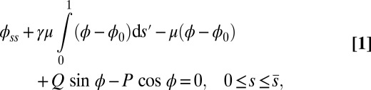
  , the dimensionless geometrically exact equilibrium equations for the centerline of the filament bundle are given by
 |
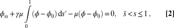 |
with  Here, μ denotes the sliding resistance parameter, which measures the relative importance of the effective bundle elastic rigidity compared with the cross-linking elastic resistance, and γ measures the relative importance of basal compliance to the passive sliding response. Zero basal sliding resistance and rigid anchoring (a welded base) correspond to
  and
and  , respectively, so that
  . When no sliding displacements are permitted, both μ and γ vanish, from whence in which case Eqs. 1 and 2 describe the classical Euler elastica (15, 16). When
  , the elastic coupling of the external filaments creates a nonlocal body couple acting on the filament bundle. Finally, we assume the contact moment is continuous between the active
  and passive
  regions, which, in turn, implies from the moment balance that
  is continuous at the point of force application.
Boundary Conditions.
Following typical experimental conditions, we consider the distal boundary to be absent of external moments,  , whereas the basal end is assumed to be clamped,
 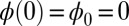 (i.e., no rotation is permitted). Across the actuation point
  , the external load induces a discontinuity on the contact forces that results in a jump in
  ; thus, the curvature,
  , is continuous but not differentiable at
  . Moreover, because the passive region is free from external moments and contact forces, we have
  from the moment balance. The system is completed either by prescribing the external load F, referred to as a traction (soft or dead-load) problem (15, 16), or by imposing displacement constraints at the actuation point,
 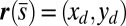 , so that the axial and transversal loads are implicitly determined by the prescribed coordinate position, which corresponds to the displacement (hard) boundary problem (15, 16). Here, we consider horizontal displacements of the actuation point
  , such that
  , by varying the displacement parameter, defined as
  (i.e., the horizontal distance between the actuation point of a postbuckled configuration,
  , and its undeformed reference position,
  ).
).
Exact Solution of the Passive Region.
The governing Eqs. 1 and 2 are simplified by finding an implicit analytical solution for Eq. 2 for a given angle  at the actuation point. In the passive region, we have
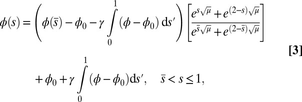 |
which conveniently depends on the two parameters of the system, γ and μ. Nonlocal effects associated with the interlayer shear also manifest via an explicit coupling with the active bent region  . The solution (Eq. 3) automatically satisfies the free momentum conditions both at the boundaries and throughout the passive section of the bundle. The absence of external forces and torques in this region implies that the deformation of the passive section is a direct consequence of a balance between the pure elastic bending moment and the passive sliding resistance for
  . Furthermore, Eq. 3 is a simple analytical expression, valid for geometrically nonlinear deformations, that can be readily used to extract empirical material quantities from static configurations, as discussed below.
The Counterbend Effect
Numerical steady-state solutions were generated by considering external forces acting at the midpoint of the filament bundle,  , with the resulting horizontal displacement of the actuation point within the range
 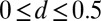 , while keeping the clamped basal end at the origin of the reference frame. We investigate a wide range of physiologically relevant parameters,
  and
and  , that are consistent with typical physical quantities extracted from experimental models of flagellar axonemes (10, 12, 13, 15, 16, 20), as detailed in SI Text, section 1.
We begin by presenting in Fig. 3 numerical solutions of postbuckled configurations of filament bundles with sliding resistance  and three distinct horizontal displacements d, for two cases: (i) the filaments within the bundle are rigidly anchored at the base,
  , so that no sliding is allowed at
  (welded bundle), and (ii) the filaments at the base are free from any additional sliding resistance,
  . The most evident feature in Fig. 3 is the emergence of opposing curvatures beyond the actuation point, namely, the counterbend effect. The magnitude of these counterbend curvatures, however, depends on details of the elastic sliding resistance, basal compliance, and imposed bending of the active region
  . The counterbend deformation increases as the active region progressively deforms with increments in d, regardless of γ. Nevertheless, the sensitivity of the counterbend effect, for a given sliding resistance parameter, is still regulated by the basal compliance. Additional sliding resistance at
  induces larger counterdeformations beyond the actuation point (Fig. 3 A–C), compared with the symmetrical bundle case (Fig. 3 E and F). Furthermore, the resulting sliding displacement
  , represented by the overlaid color surface in Fig. 3, demonstrates a nontrivial coupling between bending deformations and the sliding filament distribution. In particular, when
  in Fig. 3 A–C,
  vanishes and the sliding displacement is relatively elevated, especially close to the actuation point in the active region. The opposite scenario is depicted in Fig. 3 D–F for
  , where the overall magnitude of sliding displacement is reduced due to nonzero displacements at the base
  , further exemplifying how local deformations instigate nonlocal effects at distant parts of the bundle. It is noteworthy that buckling experiments of flagellar axonemes (12) also reported an increasing counterbend magnitude with the imposed deformation, in agreement with the predictions of our model (e.g., Fig. 1).
Fig. 3.
Demonstration of the counterbend effect on filament bundles for three horizontal displacements d, a sliding resistance  , and two basal constraints: internally anchored filaments at
  (welded bundle) (A–C) and filament bundles with no basal sliding resistance (D–F). The black arrows depict the actuation force required to hold the filament bundle at a given displacement d and the associated reaction force at the clamped base. The magnitude of this force was found to be
  for
for  in A–C and
  for
for  in D–F, respectively. Sliding deformations are represented by the internal connecting links, where the overlaid surface coloring indicates the sliding displacement distribution
  relative to the bundle diameter b.
The elastic cross-linking resistance is able to induce further different mechanical responses: Whereas the interfilament resistance instigates large-scale counterdistortions within the distal region once buckling occurs, it also reinforces the overall structure, so that a higher load is needed to achieve buckling. Fig. 4 A and B illustrate how the applied load required to horizontally displace the actuation point and the counterbend effect, characterized by the countercurvature developed at the actuation point  , are modified by the triplet
  . In general, both
  and
and  in Fig. 4 A and B grow as the displacement d increases, with more extensive growth for larger values of μ and lower values of γ. In particular, the maximum load a filament bundle can sustain without buckling, referred to as the critical load, and indicated by the value of
  at
at  , is doubled for
  compared with the force required to buckle an ordinary Euler-elastica. Furthermore, the similarity between the load displacement curves in Fig. 4A demonstrates how the mechanical response of the general filament bundle is correlated with the behavior of simpler Euler–Bernoulli filaments, especially for symmetrical bundles
  , despite its internal complexity.
Fig. 4.

Force-displacement relation, countercurvature, and internal mechanics of filament bundles: the actuation force magnitude,  , relative to the associated Euler bucking load
  (A), and the absolute countercurvature measured at the actuation point,
  , as a function of d (B), for a Euler–Bernoulli rod (black curve), and filament bundles with sliding resistances
  (blue curves) and
  (red curves) for
  (solid blue and red curves) and
  (dashed blue and red curves). Note that B outlines the counterbend and its sensitivity to different quantities in the
  -parameter space. Because
  is identically zero for the Euler–Bernoulli case, the black curve is omitted in B. (C) Horizontal and vertical load, Q and P, respectively, required to hold a filament bundle at a distance
  , as a function of μ and γ, depicted by the blue and orange contour lines. Note that the contours of Q and P conveniently form a mesh in
  -parameter space. (D) Curvature (solid curves) and interfilament sliding moment
  (dashed curves) as a function of s, for
  ,
,  , for three horizontal displacements d, as in Fig. 3. Darker blue curves are used for larger d, and black markers show the actuation point
  .
.
The existence of filament bundles with distinct values of μ and γ that share the same force magnitude  , for a given displacement d, as depicted in Fig. S1, seems to compromise the measurement of material parameters from typical load displacement experiments in flexural tests. Nevertheless, the interplay between the horizontal and vertical load is characterized by an invertible mapping between
  and
and  , as highlighted in Fig. 4C for fixed d, by the fact that the contours of Q and P form a mesh in
  -parameter space. Hence, knowledge of Q, P, and d allows the simultaneous parameter estimation of μ and γ. Furthermore, the bending stiffness
  can be determined from the actuation force and flagellar length via
 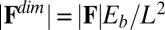 . Higher precision may also be achieved by considering distinct
  -landscapes as d is adjusted.
Internal Mechanics.
We now turn our attention to the consequences of interfilament sliding resistance on the internal mechanics of filament bundles. We start with Fig. 4D, which presents the typical behavior of the curvature against arc length (continuous curves) as the horizontal displacement d gradually increases (darker curves are used for larger d). As one would expect from Fig. 3, the curvature has a nonmonotonic behavior characterized by the formation of a peak adjacent to the actuation point (black marker); in addition, this peak increases in magnitude as the active region progressively deforms. The break point at  marks the maximum of the countercurvature developed within the distal region, relative to the imposed curvature at
  , and it gradually relaxes to zero at the free end of the filament bundle. Despite the smooth appearance in Fig. 3, note that
  is continuous but not differentiable due to a jump in
  introduced by the external load.
To understand counterbending further, consider Fig. 4D once more; in particular, examine how the dimensionless elastic bending moment  and interfilament sliding moment
  , defined via
  , are distributed along the bundle. Because the filament bundle is free from external forces and torques in the passive region, the total moment vanishes,
  ; thus, for
  , the sliding moment offsets the bending moment,
  , which is also a monotonic function in this region (Eq. 3). Both bending and sliding moments are restorative; therefore, both act in the direction required to return the filament bundle to its reference configuration, given a localized imposed bending. This concomitant action is observed in Fig. 4D for peak curvatures around
  . Because this behavior in the active region must match the mechanics of the passive region, where the sliding moment offsets the elastic bending moment, a relative change in the sign of one of the moments must be induced as s increases toward
  , as observed in Fig. 4D. In addition, the sliding moment is cumulative and is given in terms of integrals of the angle ϕ. For a sufficiently sharp curvature in a localized region, this aspect of the configuration will dominate the behavior of these integrals; thus, the sliding moment will retain its sign. This forces the elastic bending moment,
  , to change sign, as illustrated in Fig. 4D. This, in turn, induces the filament bundle to deform in opposition to the stored sliding moment
  at the passive section, thus generating the characteristic countercurvature beyond the actuation point.
Extracting Material Parameters: An Example.
Our mathematical formulation suggests that key material parameter properties of cross-linked filament bundles can be extracted from counterbend experiments. We consider existing data reported by Pelle et al. (12) for buckling experiments investigating sea urchin flagellar axonemes, with disabled molecular motors, by adhering the sperm head to a coverslip and externally actuating the flagellum with a microprobe, as previously shown in Fig. 1. However, the proximity of the sperm flagellum to the coverslip near the adhered sperm head implies that the proximal flagellum can sometimes also adhere to the substrate, preventing further local deformations. Two common experimental conditions are depicted in Fig. 5: (i) when the flagellum is relatively free from surface adhesion, indicated by a considerable near-base flagellar distortion in Fig. 5A, and (ii) when the proximal flagellum region is attached to the substrate, illustrated by straight near-base configuration in Fig. 5B.
Fig. 5.
Model curve fitting with existing buckling experiments by Pelle et al. (12) for sea urchin flagellar axonemes. The captured flagellar profile is indicated in blue, and the associated angle relative to the base (blue curves) is plotted as a function of arc length for two micrographs (A and B), where the black markers depict the location of the probe actuation. The red curves show the model curve-fitting result from the geometrically exact solution of the passive region (Eq. 3), where the values of μ and γ have been simultaneously extracted, as indicated above. Micrographs adapted from Pelle et al. (12) with permission from John Wiley and Sons, © Wiley-Liss Inc.
The digitally captured flagellum configurations, and their associated angle relative to the base as a function of arc length, are represented by blue curves in Fig. 5. A least-squares fitting of the captured angle relative to the base,  , with the analytical formula obtained for geometrically nonlinear deformations of the passive region (Eq. 3) is indicated by the red curves. An excellent match between Eq. 3 and the captured profile is obtained, as indicated in Fig. 5. Due to the complex interplay among different components within the axoneme, the measured values of μ and γ result from the combined effect of the total interfilament and basal sliding resistance, respectively. For the physiologically relevant case (Fig. 5A), the measured interfilament sliding resistance,
  , reveals that large internal bending moments are induced along the flagellum by the resulting sliding friction between microtubules, including nexin links, radial spokes, and filament-to-filament contact friction. Moreover, the observed compliance at the base,
  , demonstrates that although the sliding resistance of the connecting piece between the sperm head and the flagellum is relatively low for sea-urchin sperm, it equally contributes to the overall material response.
The calculated material parameters in Fig. 5B, on the other hand, show a large discrepancy relative to Fig. 5A. Indeed, the estimate  indicates that the microtubules in this (demembranated) axoneme are prevented from sliding at the base due to the attachment of the proximal axoneme to the coverslip. The resulting suppression of interfilament sliding within the attachment region, whose extent is unknown, prevents a reliable assessment of the material parameters.
Discussion
The filament bundle Euler-elastica equations revealed that counterbend events are an intrinsic signature of resistance to the relative filament sliding in cross-linked bundles, which also acts to reinforce the elastic structure, requiring a higher load to achieve buckling. The expected monotonicity between moments and curvature, from the traditional Euler–Bernoulli model, is lost. The curvature is marked by a sudden sign change approaching the actuation point, accompanied by alterations of the cross-linking sliding moments to match the mechanics of the passive region (Fig. 4D). Furthermore, the emergence of countercurvatures without requiring distortions in the bundle diameter (19) establishes the counterbend as a genuine manifestation of the coupling between flexure and interfilament sliding.
Despite the positive correlation between the mechanical response of filament bundles and Euler–Bernoulli filaments (Fig. 4A), data-fitting procedures with the widely used Euler-elastica would lead to inaccurate bulk material measurements for filament bundles. This might explain, for example, why experimental investigations, before the discovery of the counterbend (11), failed to assess the true significance of the cross-linking mechanics. Counterbend-type experiments, however, yield direct measurements of the basal compliance and the interfilament elastic resistance, as demonstrated by the mesh-like pattern in Fig. 4C, whereas the elastic bending stiffness is solely determined by knowledge of the actuation force, nondimensionalized by  . In particular, the exact solution for the deformation of the distal region (Eq. 3) allowed the direct extraction of material parameters via standard curve-fitting procedures, as illustrated with existing experiments for sea urchin sperm flagellum (12). An excellent match was found with the observed counterbend deformation (Fig. 5), further validating the physical principles behind the presented formulation. Nonetheless, we have shown that the action of contact forces that are not accounted for in the model, such as surface flagellum adhesion, may suppress interfilament sliding, and thus prevent the measurement of the bulk material parameters. Consequently, due to the sensitivity of the filament bundle elastica response to external contact forces, moments, and different boundary conditions, caution is required in the analysis of static configurations from experimental data.
Although the counterbend successfully exposes the structural significance of the interfilament sliding resistance, the constitutive material relationships for cross-linking proteins in filament bundles and basal compliance in flagella are still unknown and may vary considerably for different systems. The appropriate constitutive relations, which, in general, can be nonlinear functions of the strain, may be assessed by generalizing the formulation presented here accordingly, especially by considering multiple geometrical configurations in experiments. Likewise, our model can be made more general by considering 3D aspects (3–5, 25).
Finally, large-scale counterbend effects are likely to play an important role at the dynamical level, for instance, during flagellar wave propagation in swimming sperm. Here, active sliding displacement in one section of the flagellum would tend to induce a compensatory deformation elsewhere due to a counterbend formation, thus contributing to the coordination of the waveform along the flagellum. However, this is a far from complete picture of how structure influences dynamical function. For instance, we have neglected radial axonemal deformations because these are observed to be relatively small compared with our predicted sliding displacements but nonetheless may be critical in the coordination of molecular motors, as with the “geometric clutch hypothesis” (19), further emphasizing that the dynamic flagellar wave may be critically dependent on the underlying structural mechanics.
Supplementary Material
Acknowledgments
We thank C. B. Lindemann and K. A. Lesich for many helpful discussions and for providing details from sperm buckling experiments, including the micrographs analyzed in this work, and also gratefully acknowledge C. J. Brokaw for continued insight. H.G. thanks the CAPES Foundation (Grant BEX 4676/06-8); WYNG Foundation; and Trinity Hall, University of Cambridge. This publication is based on work supported, in part, by Award KUK-C1-013-04 from King Abdullah University of Science and Technology. A.G. is a Wolfson Royal Society Merit Holder and is supported by a Reintegration Grant under European Commission Framework VII.
Footnotes
The authors declare no conflict of interest.
This article is a PNAS Direct Submission.
This article contains supporting information online at www.pnas.org/lookup/suppl/doi:10.1073/pnas.1302113110/-/DCSupplemental.
References
- 1.Alberts B. Molecular Biology of the Cell. New York, NY: Garland Science; 2002. [Google Scholar]
- 2.Howard J. Mechanics of Motor Proteins and the Cytoskeleton. Sunderland, MA: Sinauer; 2001. [Google Scholar]
- 3.Heussinger C, Schüller F, Frey E. Statics and dynamics of the wormlike bundle model. Phys Rev E Stat Nonlin Soft Matter Phys. 2010;81(2 Pt 1):021904-1–021904-15. doi: 10.1103/PhysRevE.81.021904. [DOI] [PubMed] [Google Scholar]
- 4.Bathe M, Heussinger C, Claessens M, Bausch AR, Frey E. Cytoskeletal bundle mechanics. Biophys J. 2008;94(8):2955–2964. doi: 10.1529/biophysj.107.119743. [DOI] [PMC free article] [PubMed] [Google Scholar]
- 5.Claessens MM, Bathe M, Frey E, Bausch AR. Actin-binding proteins sensitively mediate F-actin bundle stiffness. Nat Mater. 2006;5(9):748–753. doi: 10.1038/nmat1718. [DOI] [PubMed] [Google Scholar]
- 6.Tolomeo JA, Holley MC. Mechanics of microtubule bundles in pillar cells from the inner ear. Biophys J. 1997;73(4):2241–2247. doi: 10.1016/S0006-3495(97)78255-9. [DOI] [PMC free article] [PubMed] [Google Scholar]
- 7.Fawcett D, Bloom W, Raviola E. A Textbook of Histology. New York: Chapman & Hall; 1994. [Google Scholar]
- 8.Lindemann CB, Rudd WG, Rikmenspoel R. The stiffness of the flagella of impaled bull sperm. Biophys J. 1973;13(5):437–448. doi: 10.1016/S0006-3495(73)85997-1. [DOI] [PMC free article] [PubMed] [Google Scholar]
- 9.Okuno M. Inhibition and relaxation of sea urchin sperm flagella by vanadate. J Cell Biol. 1980;85(3):712–725. doi: 10.1083/jcb.85.3.712. [DOI] [PMC free article] [PubMed] [Google Scholar]
- 10.Okuno M, Hiramoto Y. Direct measurements of the stiffness of echinoderm sperm flagella. J Exp Biol. 1979;79(1):235–243. [Google Scholar]
- 11.Lindemann CB, Macauley LJ, Lesich KA. The counterbend phenomenon in dynein-disabled rat sperm flagella and what it reveals about the interdoublet elasticity. Biophys J. 2005;89(2):1165–1174. doi: 10.1529/biophysj.105.060681. [DOI] [PMC free article] [PubMed] [Google Scholar]
- 12.Pelle DW, Brokaw CJ, Lesich KA, Lindemann CB. Mechanical properties of the passive sea urchin sperm flagellum. Cell Motil Cytoskeleton. 2009;66(9):721–735. doi: 10.1002/cm.20401. [DOI] [PubMed] [Google Scholar]
- 13.Riedel-Kruse IH, Hilfinger A, Howard J, Jülicher F. How molecular motors shape the flagellar beat. HFSP J. 2007;1(3):192–208. doi: 10.2976/1.2773861. [DOI] [PMC free article] [PubMed] [Google Scholar]
- 14.Gaffney EA, Gadêlha H, Smith DJ, Blake JR, Kirkman-Brown JC. Mammalian sperm motility: Observation and theory. Annu Rev Fluid Mech. 2011;43:501–528. [Google Scholar]
- 15.Antman S. Nonlinear Problems of Elasticity. Springer-Verlag New York, Inc; 2005. [Google Scholar]
- 16.Fung YC, Tong P. Classical and Computational Solid Mechanics. Singapore: Word Scientific; 2001. [Google Scholar]
- 17.Satir P. Studies on cilia: II. Examination of the distal region of the ciliary shaft and the role of the filaments in motility. J Cell Biol. 1965;26(3):805–834. doi: 10.1083/jcb.26.3.805. [DOI] [PMC free article] [PubMed] [Google Scholar]
- 18.Brokaw CJ. Bend propagation by a sliding filament model for flagella. J Exp Biol. 1971;55(2):289–304. doi: 10.1242/jeb.55.2.289. [DOI] [PubMed] [Google Scholar]
- 19.Lindemann CB, Mitchell DR. Evidence for axonemal distortion during the flagellar beat of Chlamydomonas. Cell Motil Cytoskeleton. 2007;64(8):580–589. doi: 10.1002/cm.20205. [DOI] [PubMed] [Google Scholar]
- 20.Minoura I, Yagi T, Kamiya R. Direct measurement of inter-doublet elasticity in flagellar axonemes. Cell Struct Funct. 1999;24(1):27–33. doi: 10.1247/csf.24.27. [DOI] [PubMed] [Google Scholar]
- 21.Hines M, Blum JJ. Bend propagation in flagella. I. Derivation of equations of motion and their simulation. Biophys J. 1978;23(1):41–57. doi: 10.1016/S0006-3495(78)85431-9. [DOI] [PMC free article] [PubMed] [Google Scholar]
- 22.Lindemann C, Kanous K. A “geometric clutch” hypothesis to explain oscillations of the axoneme of cilia and flagella. J Exp Biol. 1995;168(1):175–189. [Google Scholar]
- 23.Camalet S, Julicher F. Generic aspects of axonemal beating. New J Phys. 2000;2(1):24.1–24.23. [Google Scholar]
- 24.Brokaw CJ. Computer simulation of flagellar movement VIII: Coordination of dynein by local curvature control can generate helical bending waves. Cell Motil Cytoskeleton. 2002;53(2):103–124. doi: 10.1002/cm.10067. [DOI] [PubMed] [Google Scholar]
- 25. Hilfinger A (2006) Dynamics of cilia and flagella. PhD dissertation (Technische Universität Dresden, Germany)
- 26.Gadêlha H, Gaffney EA, Smith DJ, Kirkman-Brown JC. Nonlinear instability in flagellar dynamics: A novel modulation mechanism in sperm migration? J R Soc Interface. 2010;7(53):1689–1697. doi: 10.1098/rsif.2010.0136. [DOI] [PMC free article] [PubMed] [Google Scholar]
- 27.Lindemann CB, Orlando A, Kanous KS. The flagellar beat of rat sperm is organized by the interaction of two functionally distinct populations of dynein bridges with a stable central axonemal partition. J Cell Sci. 1992;102(Pt 2):249–260. doi: 10.1242/jcs.102.2.249. [DOI] [PubMed] [Google Scholar]
Associated Data
This section collects any data citations, data availability statements, or supplementary materials included in this article.