Abstract
A novel handheld probe based on a microelectromechanical systems (MEMS) scanning mirror for three-dimensional (3D) fluorescence molecular tomography (FMT) is described. The miniaturized probe consists of a MEMS mirror for delivering an excitation light beam to multiple preselected points at the tissue surface and an optical fiber array for collecting the fluorescent emission light from the tissue. Several phantom experiments based on indocyanine green, an FDA approved near-infrared (NIR) fluorescent dye, were conducted to assess the imaging ability of this device. Tumor-bearing mice with systematically injected tumor-targeted NIR fluorescent probes were scanned to further demonstrate the ability of this MEMS-based FMT for imaging small animals.
1. Introduction
Fluorescence molecular tomography (FMT) is an emerging modality that can three-dimensionally image molecular activities at tissue depths of several centimeters [1–4]. FMT is a highly sensitivity technique and can detect nanomole to picomole fluorophores [5–7]. While FMT has been primarily used for preclinical animal studies [8], it has been recently applied for detecting breast cancer in humans [9].
In applications such as intraoperative imaging and endoscopic examination, miniaturization of FMT is required. We recently reported a handheld FMT probe based on a fiber-optic array for both delivery of excitation light and collection of fluorescent emission [10]. While it was feasible to use this probe for intraoperative imaging of tumors, the probe was relatively bulky and the delivery of excitation light was slow due to the use of mechanical translations. Here we describe a microelectromechanical systems (MEMS) scanning-mirror-based FMT probe that overcomes the limitations associated with our previous probe. The MEMS scanning mirror has been widely used for various imaging probes with the advantages of small size, flexibility in the scanning pattern, and high reliability [11–14]. We validate this MEMS-based FMT probe using indocyanine green (ICG)-containing phantoms and demonstrate its application to tumor imaging in small animals.
2. Instrumentation
The schematic of our MEMS-based FMT imaging system is shown in Fig. 1(a), where we see that the miniaturized imaging probe consists of two parts. One part houses a fixed mirror and a MEMS mirror for laser beam scanning. The other part is a ring-shaped detection optical fiber array (38 optical fibers in total) for collecting the fluorescent emission light. In this FMT system, a continuous wave (CW) 785 nm diode laser (Model DL7140-201S, Sanyo, Japan) is used as the excitation light source. The excitation light is delivered to the sample through the fixed mirror and the scanning MEMS mirror. The optical fiber array collects and sends the emission light to a 1024 × 1024 pixel PIXIS CCD camera (Princeton Instruments, Trenton, New Jersey). The emission light is bandpass filtered at 830 nm. The imaging probe [Fig. 1(b)] has an inner and outer diameter of 12 mm and 25 mm, respectively.
Fig. 1.
(Color online) (a) Schematic of the MEMS-based FMT system, (b) photograph of the imaging probe, and (c) scanning electron microscopic (SEM) image of the MEMS mirror.
Figure 1(c) shows a scanning electron microscopic (SEM) image of the MEMS mirror. The chip size is 2 mm × 2 mm and the mirror plate is 1 mm diam. The MEMS mirror has four Al/SiO2 bimorph-based actuators made from a zero initial tilt and lateral shift-free (ZIT-LSF) design. Due to the Joule heating effect, when differential voltage pairs are applied to the actuators, either tip or tilt motion of the mirror plate can be generated, and thus two-dimensional (2D) scanning can be realized.
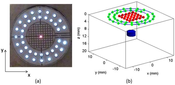
The MEMS mirror is controlled by two 2-channel function generators (AFG3022B, Tektronix). The delivery of the excitation laser beam to the preselected source positions is realized by applying DC voltages to the MEMS mirror, as a DC voltage will result in a fixed displacement of the MEMS mirror. For determining the source positions, a paper with grids in the center area and marked positions of optical fibers was attached to the end of the imaging probe [Fig. 2(a)]. In this study, 21 source positions were generated by the MEMS mirror scanning. The maximum voltage of 1.5 V was used to obtain an approximately 8 mm × 8 mm scanning area. The positions of the sources and detectors are schematically shown in Fig. 2(b). The diameters of the two detector rings were 16 mm and 21 mm.
Fig. 2.

(Color online) (a) Photograph of the end view of the imaging probe with the grid paper attached and with one laser scanning position (red center) shown, (b) arrangement of the sources (inner red dots) and detectors (green dots on outer rings) for FMT and one target (blue below).
3. Phantom and Mouse Experiments
Phantom experiments were performed to validate the MEMS-based FMT probe using ICG-containing targets with different depths, sizes, and contrasts. A cubic background phantom (28 mm × 28 mm × 20 mm) consisted of 1% Intralipid, India ink, and 2% Agar powder, resulting in an absorption coefficient of 0.007 mm−1 and reduced scattering coefficient of 1.0 mm−1. For depth resolution validation, a small cylinder of 4 mm diam. with an ICG concentration of 2 μM was placed at depths of 2, 4, and 6, respectively. For the target detectability study, a small cylinder containing 2 μM ICG with a size of 4, 2, and 1 mm diam., respectively, was embedded at a depth of 5 mm. For contrast resolution testing, a cylinder of 4 mm diam. arranged at a depth of 5 mm had a varied ICG concentration of 1, 0.5, and 0.1 μM, respectively.
For all the experiments, the exposure time of the CCD camera for each frame varied from 1 to 6 s depending on the signal-to-noise ratio.
To further demonstrate the ability of our MEMS FMT probe, tumor-bearing mice were imaged. A mouse mammary tumor model with a 4T1 tumor cell line was used. Near-infrared 830 dye (NIR-830) was used as the fluorescent contrast agent. Amino-terminal fragment (ATF) conjugated-NIR 830-iron oxide nanoparticles (NIR-830-ATF-IONP) are able to specifically target an urokinasetype plasminogen activator (uPA) receptor overexpressed in breast cancer tissue [15]. As a control, a nontargeted bovine serum albumin-peptide NIR-IONP probe (NIR-830-BSA-IONP) was used for comparison. The tumor-bearing mice received a 100 pmol tail vein injection of NIR-830-ATF-IONP or NIR-830-BSA-IONP. Planar fluorescence imaging was performed 24 hours after the injection using Kodak FX in vivo imaging system.
Three-dimensional (3D) FMT images were reconstructed using a finite-element-based reconstruction algorithm described in detail previously [16,17]. Briefly, this 3D FMT algorithm is based on the coupled diffusion equations that describe propagation of both excitation and emission light in tissue. The nonzero photon density or type III boundary conditions are applied. The finite element method is used to discretize the diffusion equations and obtain the matrix representations capable of inverse problem solution. Fluorescence images are formed by iteratively solving the forward equations and updating the optical and fluorescent property distributions from presumably uniform initial estimates of these properties. A 3D finite element mesh with 8593 nodes and 45,360 tetrahedral elements was used for all the imagereconstructions.
4. Results and Discussion
A. Phantom experiments
1. Depth Resolution
Figure 3 shows the reconstructed FMT images at different depths along the YZ planes where the black square in each image indicates the exact target location. We can see that the target can be well reconstructed up to a depth of 6 mm. We note that the reconstructed target size is increasingly overestimated with increased target depth. The maximum depth resolution of this imaging probe (~6–7 mm) is limited by the largest source-detector separation given in this probe.
Fig. 3.

(Color online) FMT images at different target depths.
2. Target Detectability
Figure 4 shows the reconstructed FMT images for a single target having different size. As can be seen, the target is quantitatively recovered in terms of the target size for all three cases. For the 1 mm diam. target, we note that the target location is slightly shifted along the depth direction with some notable boundary artifacts. It is known that the target detectability depends on the target depth: the deeper the target, the worse the target detectability.
Fig. 4.

(Color online) FMT images for a single target having different sizes.
3. Contrast Resolution
Figure 5 shows the reconstructed FMT images of a target with ICG concentrations of 1 μM, 0.5 μM, and 0.1 μM. The target was located at a depth of 5 mm for all three cases. From the images, we can see that the target can be well reconstructed even with an ICG concentration as low as 0.1 μM. Considerably higher concentrations of ICG have been previously used in humans for lymph node mapping [18].
Fig. 5.

(Color online) FMT images for a single target having different ICG concentrations.
B. Mouse Experiments
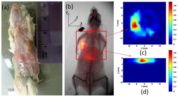
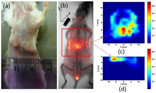
Figures 6 and 7 show the reconstructed FMT images for a tumor-bearing mouse administrated with 100 pmol NIR-830-ATF-IONP and NIR-830-BSA-IONP, respectively. The 2D planar fluorescence images by the Kodak FX system are also provided for comparison [Figs. 6(b) and 7(b)]. We can see that the cross-section slices of the FMT images are well consistent with the 2D planar images for both cases. Figures 6(d) and 7(d) give the depth information of the tumor along the YZ planes. We also note that the NIR-830-ATF-IONP probe was well targeted to the tumor cells, evident from the concentrated high tumor-to-tissue contrast seen in Figs. 6(c) and 6(d), while the NIR-830-BSA-IONP probe was not specifically bound to the tumor cells and distributed mostly in a large area of normal tissue [Figs. 7(c) and 7(d)].
Fig. 6.

(Color online) FMT images using NIR-830-ATF-IONP: (a) photograph of the mouse, (b) x ray/planar fluorescence image of the mouse, (c) cross section of the FMT slice, (d) the sagittal FMT slice. The red square in (b) indicates the FMT imaging area.
Fig. 7.
(Color online) FMT images using NIR-830-BSA-IONP: (a) photograph of the mouse, (b) x ray/planar fluorescence image of the mouse, (c) cross section of the FMT slice, (d) the sagittal FMT slice. The red square in (b) indicates the FMT imaging area.
5. Conclusions
We have presented a miniaturized fluorescence molecular tomography probe using a MEMS scanning mirror and validated the system using phantom and mouse experiments. Unlike conventional means for delivery of excitation light using optical fibers, MEMS mirror-based light delivery is compact and can obtain as many source positions with basically any desired pattern. The results obtained have shown that targets can be sensitively detected at a depth of up to 6–7 mm. We realize that there are still some improvements needed in order to translate this technique to human applications. For example, the imaging probe needs to be made smaller and more portable for clinical applications such as image-guided surgery. In addition, the time needed for data acquisition and image reconstruction needs to be significantly reduced to perform real-time image-guided surgery.
Acknowledgments
This research was supported in part by the J. Crayton Pruitt Endowment and by a grant from the NIH (R01 CA133722).
References
- 1.Leblond F, Davis SC, Valdes PA, Pogue BW. Preclinical whole-body fluorescence imaging: review of instruments, methods and applications. J. Photochem. Photobiol. B. 2010;98:77–94. doi: 10.1016/j.jphotobiol.2009.11.007. [DOI] [PMC free article] [PubMed] [Google Scholar]
- 2.Montet X, Figueiredo J, Alencar H, Ntziachristos V, Mahmood U, Weissleder R. Tomographic fluorescence imaging of tumor vascular volume in mice. Radiology. 2007;242:751–758. doi: 10.1148/radiol.2423052065. [DOI] [PubMed] [Google Scholar]
- 3.Reynolds JS, Troy TL, Mayer RH, Thompson AB, Waters DJ, Cornell KK, Snyder PW, Sevick-Muraca EM. Imaging of spontaneous canine mammary tumors using fluorescent contrast agents. Photochem. Photobiol. 1999;70:87–94. [PubMed] [Google Scholar]
- 4.Tan Y, Yang L, Jiang H. Digital Holography and Three-Dimensional Imaging. OSA Technical Digest (CD); Optical Society of America; 2010. DOT guided fluorescence molecular tomography of tumor cell quantification in mice. paper JMA69. [Google Scholar]
- 5.Weissleder R, Tung CH, Mahmood U, Bogdanov A. In vivo imaging of tumors with protease-activated near-infrared fluorescent probes. Nat. Biotechnol. 1999;17:375–378. doi: 10.1038/7933. [DOI] [PubMed] [Google Scholar]
- 6.Ntziachristos V, Tung C, Bremer C, Weissleder R. Fluorescence molecular tomography resolves protease activity in vivo. Nat. Med. 2002;8:757–761. doi: 10.1038/nm729. [DOI] [PubMed] [Google Scholar]
- 7.Marshall MV, Rasmussen JC, Tan IC, Aldrich MB, Adams KE, Wang X, Fife CE, Maus EA, Smith LA, Sevick-Muraca EM. Near-infrared fluorescence imaging in humans with indocyanine green: a review and update. Open Surg. Oncol. J. 2010;2:12–25. doi: 10.2174/1876504101002010012. [DOI] [PMC free article] [PubMed] [Google Scholar]
- 8.Graves E, Ripoll J, Weissleder R, Ntziachristos V. A submillimeter resolution fluorescence molecular imaging system for small animal imaging. Med. Phys. 2003;30:901–911. doi: 10.1118/1.1568977. [DOI] [PubMed] [Google Scholar]
- 9.Corlu A, Choe R, Durduran T, Rosen MA, Schweiger M, Arridge SR, Schnall MD, Yodh AG. Three-dimensional in vivo fluorescence diffuse optical tomography of breast cancer in humans. Opt. Express. 2007;15:6696–6716. doi: 10.1364/oe.15.006696. [DOI] [PubMed] [Google Scholar]
- 10.Zhao Q, Jiang H, Cao Z, Yang L, Mao H, Lipowska M. A handheld fluorescence molecular tomography system for intraoperative optical imaging of tumor margins. Med. Phys. 2011;38:5873–5878. doi: 10.1118/1.3641877. [DOI] [PMC free article] [PubMed] [Google Scholar]
- 11.Xi L, Sun J, Zhu Y, Wu L, Xie H, Jiang H. Photoacoustic imaging based on MEMS mirror scanning. Biomed. Opt. Express. 2010;1:1278–1283. doi: 10.1364/BOE.1.001278. [DOI] [PMC free article] [PubMed] [Google Scholar]
- 12.Sun J, Guo S, Wu L, Liu L, Choe S-W, Sorg BS, Xie H. 3D in vivo optical coherence tomography based on a low-voltage, large-scan-range 2D MEMS mirror. Opt. Express. 2010;18:12065–12075. doi: 10.1364/OE.18.012065. [DOI] [PubMed] [Google Scholar]
- 13.Jung W, Tang S, Xie T, McCormick DT, Ahn Y, Su J, Tomov IV, Krasieva TB, Tromberg BJ, Chen Z. Miniaturized probe using 2-axis MEMS scanner for endoscopic multiphoton excitation microscopy. Proc. SPIE. 2008;6851:68510D. [Google Scholar]
- 14.Xi L, Grobmyer SR, Wu L, Chen R, Zhou G, Gutwein LG, Sun J, Liao W, Zhou Q, Xie H, Jiang H. Evaluation of breast tumor margins in vivo with intraoperative photoacoustic imaging. Opt. Express. 2012;20:8726–8731. doi: 10.1364/OE.20.008726. [DOI] [PubMed] [Google Scholar]
- 15.Yang L, Peng XH, Wang YA, Wang X, Cao Z, Ni C, Karna P, Zhang X, Wood WC, Gao X, Nie S, Mao H. Receptor-targeted nanoparticles for in vivo imaging of breast cancer. Clin. Cancer Res. 2009;15:4722–4732. doi: 10.1158/1078-0432.CCR-08-3289. [DOI] [PMC free article] [PubMed] [Google Scholar]
- 16.Jiang H. Frequency-domain fluorescent diffusion tomography: a finite-element-based algorithm and simulations. Appl. Opt. 1998;37:5337–5342. doi: 10.1364/ao.37.005337. [DOI] [PubMed] [Google Scholar]
- 17.Tan Y, Jiang H. Diffuse optical tomography guided quantitative fluorescence molecular tomography. Appl. Opt. 2008;47:2011–2016. doi: 10.1364/ao.47.002011. [DOI] [PubMed] [Google Scholar]
- 18.Sevick-Muraca EM, Sharma R, Rasmussen JC, Marshall MV, Wendt JA, Pham HQ, Bonefas E, Houston JP, Sampath L, Adams KE, Blanchard DK, Fisher RE, Chiang SB, Elledge R, Mawad ME. Imaging of lymph flow in breast cancer patients after microdose administration of a near-infrared fluorophore: feasibility study. Radiology. 2008;246:734–741. doi: 10.1148/radiol.2463070962. [DOI] [PMC free article] [PubMed] [Google Scholar]


