Abstract
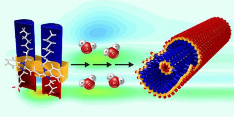
In J-aggregates of cyanine dyes, closely packed molecules form mesoscopic tubes with nanometer-diameter and micrometer-length. Their efficient energy transfer pathways make them suitable candidates for artificial light harvesting systems. This great potential calls for an in-depth spectroscopic analysis of the underlying energy deactivation network and coherence dynamics. We use two-dimensional electronic spectroscopy with sub-10 fs laser pulses in combination with two-dimensional decay-associated spectra analysis to describe the population flow within the aggregate. Based on the analysis of Fourier-transform amplitude maps, we distinguish between vibrational or vibronic coherence dynamics as the origin of pronounced oscillations in our two-dimensional electronic spectra.
1. Introduction
In photosynthesis, solar photons are converted into chemical energy with remarkably high efficiency. A thorough understanding of this process and its technological utilization will be a major contribution to a sustainable energy concept. A novel design strategy for artificial light harvesting systems relies on molecular Jelly (J) or Scheibe aggregates.1 They exhibit at least one characteristically narrow excitonic transition shifted to lower absorption energies compared to their monomeric constituents. Fluorescence typically occurs only from the lowest lying excited state. Aggregates of cyanine dyes2 are interesting candidates for artificial antenna systems. They are chemically versatile and self-assemble in aqueous solution into various extended supramolecular structures.3 Among them are cylindrical structures, sharing local dye packing features with naturally occurring chlorosomes.4 The delocalized and therefore highly polarizable π-electron system in cyanine dyes such as 3,3′-bis(3-carboxypropyl)-5,5′,6,6′-tetrachloro-1,1′-dioctylbenzimidacarbocyanine dye (C8O3) causes strong coupling between the monomers, giving rise to a delocalized excited state spread over many molecules. This delocalized, time-dependent collective excited state is referred to as an exciton. The creation and efficient migration of excitons dictate the optical properties of both artificial and natural light harvesting aggregates. Their function is to capture solar energy and to transfer it to reaction centers on a 10–100 ps time scale.5 This ultrafast time scale minimizes losses due to exciton recombination with ground state holes. When designing artificial light harvesters, it is therefore crucial to understand their population- and possible coherence-transfer dynamics. This work focuses on deciphering the ultrafast energy deactivation network in a molecular J-aggregate. We will highlight how our spectroscopic method of choice, two-dimensional electronic spectroscopy (2D-ES) uncovers ultrafast transfer channels that would be hidden in the more conventional transient absorption or pump–probe spectroscopy. We apply a global fitting routine to our 2D data for a series of waiting times to retrieve 2D decay-associated spectra (2D-DAS). In this way, we describe the aggregate’s population transfer pathways with a minimal number of decay time constants. Additionally, we discuss different oscillatory coherence signatures in our spectra and assign them to vibrational wavepacket motion on the electronic ground state or excited state vibronic coherences, respecitvely.
The aggregation behavior of the C8O3 dye has been studied in detail previously.3,6,7 The attachment of two hydrophobic octyl groups to the nitrogen atoms of the tetrachlorobenzimidacarbocyanine chromophore makes this dye amphiphilic, forcing it to aggregate in aqueous solution into bilayered structures. As revealed by cryogenic transmission electron microscopy (cryo-TEM),6,7 the aggregate’s structure is best described as a double-layered tubular strand of ∼11 nm outer diameter, total tube wall thickness of ∼4 nm, with a lamellar spacing of the individual chromophore layers of ∼2.2 nm. Within either chromophore layer, the dye molecules can be considered to be arranged in a brickwork structure.8 It was argued recently that high-energy absorption features in the tubular aggregates of the sulfonate substituted dye derivative C8S3 are better explained by a so-called extended herringbone (EHB)-type arrangement.9 In the case of pure C8O3 in dilute aqueous sodium hydroxide solution, the individual tubular aggregates commonly bundle to form thicker rope-like superhelices.6 Interestingly, this bundling effect can be completely suppressed by the addition of polyvinyl alcohol (PVA);7 for the absorption spectrum of a respective PVA/C8O3 solution, see Figure 1. It was suggested that PVA adsorbs to the outer tube surface. Thereby the single tubular strands become stabilized against bundling by the entropic forces emerging from the attached polymer chains.
Figure 1.
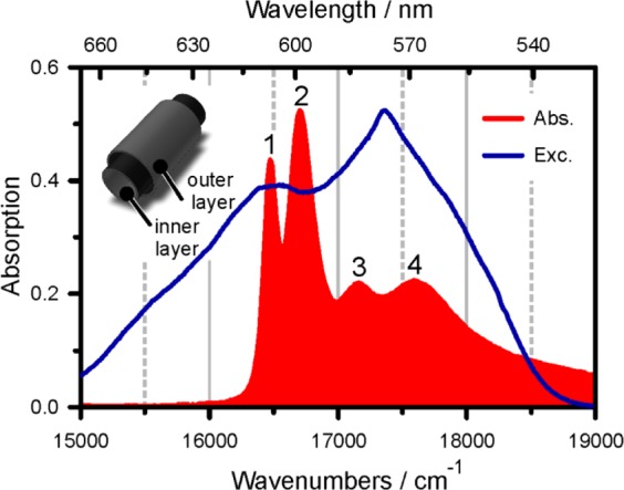
Absorption spectrum (red) of PVA/C8O3 in comparison to the employed excitation spectrum (blue). The aggregate’s double-layer architecture is sketched in the upper-left inset.
2. Experimental Section
C8O3 was obtained from FEW-Chemicals (Wolfen, Germany) and used as received. All employed solvents were spectrophotometric grade. The sample was prepared by dissolving the monomer in 10–2 M NaOH to yield a concentration of 10–4 M. This solution was stirred for 5 h, under exclusion of light, until J-aggregates were formed. Afterward, a PVA (molecular weight = 89 000–98 000) solution in 10–2 M NaOH was added to give a monomer/PVA ratio of 1:10. This stock solution was stirred for 12 h and was stable for several weeks under nitrogen atmosphere. For the measurements, the solution was diluted with 10–2 M NaOH to give a maximum absorption of not more than 0.3 in a 200 μm thick cuvette. To avoid precipitation of the several micrometer-sized aggregates on cell windows, we used a wire-guided flow jet10,11 for sample circulation. This flow-cell consists of a 300 μm thick stainless steel wire, bent to form an inverse “U”, clamped between two steel plates. To prevent the sample from photodegradation, a total volume of 15 mL was circulated with a flow rate of approximately 10 mL/min.
Raman spectra were recorded at 1064 nm using a Bruker RFS 100 FT-Raman spectrometer with a Nd:YAG laser as excitation source. The spectrum of the crystalline powder sample (monomer spectrum) was measured in a glass capillary. The spectra of aggregates were obtained on thin films prepared after placing a drop of the aqueous solutions (commonly ∼4 × 10⁻⁴ M) on a sheet of aluminum foil and drying for 3 h.
For the 2D-ES experiments, a noncollinear optical parametric amplifier (NOPA),12 pumped by a regenerative amplifier laser system (RegA 9050 from Coherent, 50 fs pulses with energy of 5.5 μJ at 200 kHz repetition rate), was used. The NOPA was equipped with a spherical mirror to collimate and focus the white light continuum into the amplifier crystal, thus enabling the generation of much broader pulse spectra. This configuration yields sub-10 fs pulses throughout the visible spectrum. In our case, the central wavelength was tuned to 16750 cm–1, with a bandwidth of 2200 cm–1 (full width at half-maximum). For the data presented in this article, the beam energy was attenuated to 0.6 nJ/pulse, corresponding to a fluence of 1.28 × 10¹³ photons/cm2. Under such low excitation densities and with the sample circulation system mentioned above, no photodegredation or exciton–exciton annihilation effects were observed in the course of the experiment.
The pulse duration was verified with in situ second harmonic generation frequency resolved optical gating (SHG-FROG)13 by placing a 10 μm thick β-barium borate (BBO) at the sample position and detection of the sum frequency of two excitation pulses. This ensured that the pulses were of the shortest duration at the location of interaction with the sample and allowed to fully compensate for any dispersion introduced by the experimental setup. For the present case, the pulses had durations of 9.3 fs, corresponding to a time-bandwidth product of 0.53.
The experimental setup, calibration procedures, data collection, and evaluation have been described in detail elsewhere.14−16 Briefly, the three excitation pulses and the local oscillator are generated in a diffractive optics based setup. The 2D spectra were acquired by scanning delay t1, the separation between the first and the second pulse. The delay between the second and third interaction t2 was kept constant. For positive (negative) values of t1, this scanning scheme delivers rephasing (nonrephasing) signal contributions. Summation of these two parts and Fourier-transformation along t1 leads to correlation spectra with purely absorptive (dispersive) lineshapes in the real (imaginary) part of the signal (the Fourier-transformation along t3 is accomplished by the spectrometer).17 These signal contributions require a determination of the absolute phase of the signal by phasing the excitation frequency integrated projection of the signal’s real part to an additionally recorded spectrally resolved pump–probe measurement (SRPP).18 Besides for phasing, we use SRPP for comparison to previously published pump–probe data and theory.19−21 When recording SRPP, we use the local oscillator as a reference beam to eliminate noise from our laser source and sample fluctuations leading to beam drifts. One of the excitation pulses (k1, k2 was blocked) acts as the pump, and the pulse along k3 acts as the probe.22 The pump beam is blocked after the sample and the probe and the reference beams are steered into the spectrometer and detected on the same 2048 × 512 pixel CCD chip. Both beams were collimated in such a way that they illuminated two clearly separated lines of approximately 10 pixels in the vertical direction. To increase data acquisition, these rows were binned, and the exposure time was set to 2 s to minimize read-out noise. Due to the 200 kHz repetition rate of our laser system, shot-to-shot detection via a chopper wheel is unfeasible. Instead, we use a shutter to record probe and reference spectra with and without the pump. In this manner, we achieve optimal data quality when averaging over 400 000 laser shots per pump–probe spectrum.
3. Results and Discussion
Based on its cylindrical symmetry, a transition along and two energetically degenerate transitions perpendicular to the long axis are predicted to dominate the aggregate’s absorption spectrum.8,23 According to Lampoura et al.,20 their splitting ΔE is inversely proportional to the cylinder diameter, or more precisely to N2, the number of exciton-forming molecules around the cylinder: ΔE/(4π2) ≈ J2/N22. J2 denotes the circumferential intermolecular coupling strength. The red-shift of the parallel transition in the aggregate with respect to the monomer transition is a measure for interchromophore coupling strengths: ΔEq = 2J1 + 2J2. J1 stands for the intermolecular coupling strength along the cylinder. For a noninteracting bilayered tubular system, one would thus expect four excitonic bands, with two transition dipole moments parallel and two perpendicular to the cylinder axis. On first sight, the linear spectrum in Figure 1 shows four distinct transitions and would therefore agree with this expectation. However, the absorption spectrum cannot be regarded as the addition of two spectra, one from the inner, one from the outer layer: linear dichroism (LD) measurements of C8O3-aggregates7 aligned in a free-flowing jet as described in the Experimental Section reveal (in agreement with ref (6)) that only one transition, band number 3, is perpendicularly polarized with respect to all other bands. We note that basic exciton models24 cannot explain three transitions oriented parallel and one perpendicular to the tubular axis. This calls for an explanation of the absorption spectrum in Figure 1, going beyond the model for excitons in a coupled bitubular system.
Changes in the solvent environment strongly affect the position and intensity of band 2 but leave band 1 nearly unaltered.9 In combination with the LD-measurements, this assigns band 2 to a longitudinal transition of the outer and band 1 to the inner cylinder. Transitions to band 3 are polarized perpendicularly to the long axis of aggregates and are shared by both layers. The assignment of band 4 on the other hand is less clear. For a pure C8O3-sample, it was speculated that band 4 originates from electronic excitations shared by several closely arranged tubes forming a superhelix.25 Pugzlys et al.21 attributed band 4 to segments of shorter delocalization length,19 possibly due to different arrangements of dye molecules, within a single tube. In an effort to clarify exciton transfer routes, fluorescence excitation spectra of PVA/C8O3 revealed7 that the energy transfer between the high-energy bands 3 and 4 and the energy sink in band 1 is efficient, while the population transfer between bands 2 and 1 appears to be kinetically hindered, leading to emission from band 2 directly. This observation is in disagreement with the ultrafast time constants retrieved from the SRPP spectra in Figure 2.
Figure 2.
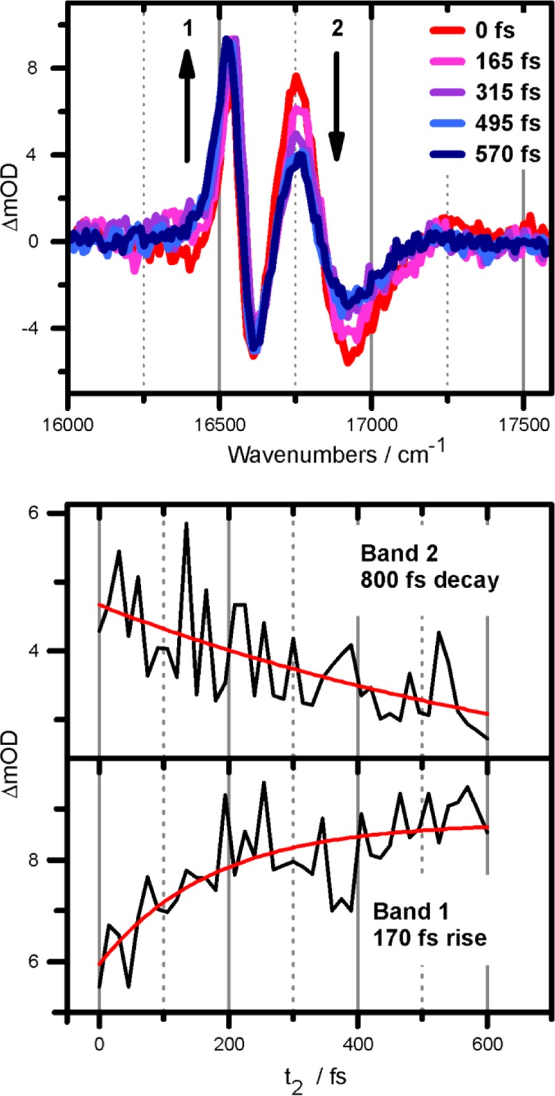
Selected SRPP spectra at indicated population times in the upper panel. The unequal time scales for rise (band 1) and decay (band 2) are depicted in the lower two panels.
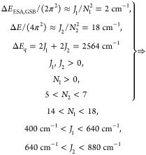
The upper panel in Figure 2 shows pump–probe spectra for selected t2-times. The two most intense features correspond to bands 1 and 2 of the absorption spectrum (see Figure 1). Based on their positive sign and the negligible Stokes shift of PVA/C8O3, they are attributed to ground state bleach (GSB) and stimulated emission (SE). The negative features stem from excited state absorption (ESA) pathways. As described previously for an exciton on cylindrical aggregates,19,20 the energy difference between ESA and GSB transition energies ΔEESA,GSB ≈ J1/N12, with J1 and N1 as the intermolecular coupling strength and the number of exciton-forming molecules on the tubular surface along the cylinder axis. Together with the relations stated above and summarized in eq 1, we derive the following relations for band 1:
 |
1 |
The relation 5 < N2 < 7 was taken from Lampoura et al.20 and describes the number of molecules, forming an exciton with momentum around the inner layer (band 1) of C8O3. Given that the inner tube diameter is nearly unchanged upon the addition of PVA,7 this relation should still hold for the current case of PVA/C8O3. ΔEESA,GSB is an average value for all recorded t2 times, i.e., between 0 and 675 fs in 15 fs steps. Due to the lack of Stokes shift in the lowest energy band,7 ΔEESA,GSB is independent of t2 for the time window of observation. The results indicate that the exciton stretches further along the cylinder surface than in the circumferential direction, N1 > N2, while the intermolecular coupling strength is stronger around than along the cylinder. For band 2 we arrive at
 |
2 |
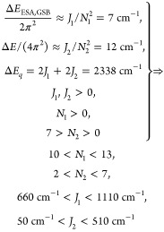
The relation 7 > N2 > 0 for band 2 stems from the assumption that the exciton on the inner layer should be better shielded and therefore delocalized over more molecules than for band 2, which is in direct contact with solvent and PVA-molecules. We note that even for the narrower inner tube, 5 < N2 < 7 is much smaller than the total number of molecules per circumference. When setting a van der Waals spacing of 0.35 nm between the chromophores,23 and tube diameters according to cryo-TEM measurements,7 we arrive at 50 (90) molecules per circumference for the inner (outer) tube for an all-parallel arrangement of chromophores with respect to the long axis of aggregates. Even if we assume an angle of 45°, the number of molecules per inner (outer) ring of 35 (62) far exceeds the number of excitonically coupled molecules 5 < N2 < 7. Hence, the ring size is not the limiting factor for N2, and N2 < 7 for the outer layer seems justified.
The two lower panels in Figure 2 depict the rise (decay) dynamics of band 1 (band 2). The measured decay time constant for band 2 is in the subpicosecond (ps) time range. This decay time is not equivalent to the 170 fs rise time of band 1, indicating that the exciton dynamics is more complex than a simple 2→1 transfer. The discrepancy between the time scales for rise of band 1 and decay of band 2 as well as the apparent differences to results from fluorescence excitation measurements, predicting an effectively nondecaying band 2, can be readily explained when examining the electronic 2D spectra in Figure 3.
Figure 3.
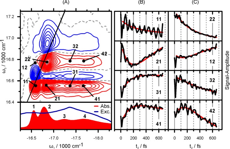
(A) Real part of the electronic 2D spectrum of PVA/C8O3 at t2 = 210 fs in comparison to the absorption and excitation spectrum in the lower panel. Positive (negative) signals are shown in red (blue) in 5% steps. The dashed gray line marks the nodal line at zero intensity. Note the unequal scales for ω1 and ω3. The thin black line marks the diagonal line of ω1 = ω3. (B,C) t2 dynamics of points indicated in the 2D spectrum are shown in black. The red line is a based on a 2D-DAS analysis explained in the Supporting Information.
2D-ES has already proven to be an incisive tool for the investigation of exciton dynamics in J-aggregates.15,25−31 The strongest features in the 2D spectrum for t2 = 210 fs in Figure 3A are the positive (red) peaks near the diagonal. Comparison to the absorption spectrum shown below the 2D plot readily assigns them to GSB and SE pathways associated with the two main absorption bands (1 and 2). Like in pump–probe, the strong negative features stem from ESA pathways. The strongest ESA signals are at the same excitation energy ω1 as the main GSB peaks but are blue-shifted in ω3. Besides the dominant diagonal peaks 11 and 22 and their respective ESA-peaks, the 2D spectrum in Figure 3 exhibits cross peaks between the two strongest absorptive bands (1 and 2) and the two weaker ones (3 and 4). The existence of cross peaks 41 and 42 is a proof of the excitonic nature of band 4, which was previously speculated to be of nonaggregated monomeric character.20 Cross peaks only arise in 2D spectra if the interrogated bands (i.e., 1, 2 and 4) share a common ground state and are therefore coupled.32
To clarify the differing time scales in the pump–probe transients in Figure 2, it is necessary to analyze individual peak dynamics as shown in the right-hand side of Figure 3. The main difference between pump–probe and 2D-ES is the excitation frequency (ω1) resolved signal in the latter. According to the projection slice theorem,18 the projection of the real part of a 2D signal onto the ω3-axis, in other words an integration along ω1, corresponds to the SRPP-signal. When considering dynamics along t2, this means that pump–probe delivers peak-intensity-weighted averages of peak dynamics extracted from 2D plots as shown in Figure 3B,C. The pump–probe transient for band 1 in Figure 2, for example, exhibits a rise time of 170 fs; in terms of 2D-ES, this means that all peaks with a detection frequency ω3 equal to band 1, i.e., peaks 11, 21, 31, and 41 in Figure 3B, constitute the 170 fs time constant from pump–probe. Peak 21 grows in time due to population transfer between bands 2 and 1 (2→1). In the averaged representation of pump–probe, we extracted a rise time of 170 fs for band 1 and could not explain the difference to the much slower decay time of band 2. 2D-ES provides a clear view on the 2→1 transfer route via the cross peak dynamics of 21. We observe a time constant too slow to be exponentially fitted within the 675 fs scan window. This slow dynamics leads to two conclusions: (i) The coupling between inner and outer tube is weak and (ii) The fact that pump–probe delivers weighted averages of the dynamics of all peaks in Figure 3B,C for bands 1 and 2, respectively, explains the discrepancy between pump–probe and fluorescence excitation measurements mentioned above. The narrow-band excitation in the latter excludes transfer from bands 4 and 3, highlighting the kinetically hindered transfer between bands 2 and 1.
Figure 3B,C shows the experimental (black) and fitted curves (red) for selected traces, taken at the (ω1, ω3) positions depicted in panel A.The fitting curves were obtained from a multidimensional decay-associated analysis of the measured 2D spectra at different t2 times, where spectra at t2 ≤ 30 fs were excluded from the 2D-DAS analysis. In the previous work of Myers et al.33 the authors analyzed the sequence of 2D spectra by fitting of individual traces with a finite number of decay times (four for all traces), varying both decay time constants and amplitudes. This approach differs strongly from the one used in our work where all traces have the same set of decay times (i.e., a global fit). While details of the novel procedure employed here can be found in the Supporting Information, we note that only three global time constants (146 fs, 450 fs, and >5 ps) are required to obtain an excellent fit of the entire 2D spectra kinetics.
Another intriguing feature of the transients in Figure 3 are the fast oscillatory components, superimposed on the slow population dynamics. These components can be of electronic (also termed excitonic) or vibrational origin, or they can originate from a mixture of both, which we denote as vibronic. The mixture occurs when weakly allowed excited vibrational levels of one molecule interact through resonance coupling with the allowed zero phonon level of a different molecule. This leads to excitonic mixing, transition dipole moment redistribution, and transition frequency shifts.34,35 Vibronic coherences can thus exhibit frequencies and enhanced amplitudes compared to the vibrational case, while showing similar lifetimes. In 2D spectra, vibronic coherences have characteristics close to those of the electronic coherences, because the regularity of the harmonic level spectrum is perturbed by interactions with electronic degrees of freedom.36,37 In order to clarify the nature of the experimentally observed coherences, we conducted a frequency domain Raman measurement of crystalline C8O3 monomer, superhelical C8O3 aggregates in solution, and PVA/C8O3 single tubular aggregates. The respective spectra are shown in Figure 4.
Figure 4.
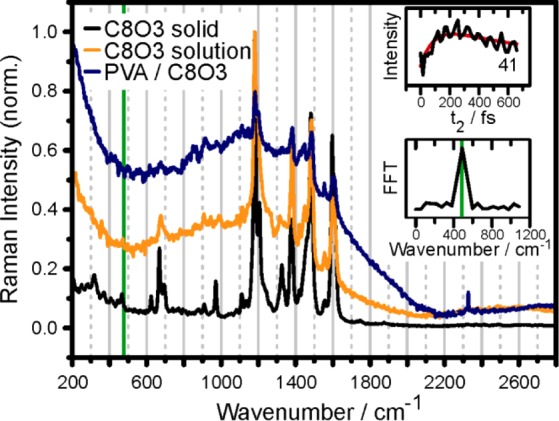
Raman spectra of crystalline C8O3 monomer (black), superhelically coiled C8O3 aggregate in aqueous solution (orange), and single tubular PVA/C8O3 aggregate (blue). The top inset shows the transient of cross-peak 41. After subtraction of the slowly varying background (red line) and Fourier-transformation, the spectrum in the lower inset is obtained. The peak around 476 cm–1 (green line) is not seen in the Raman spectra.
The Raman spectra for both C8O3 aggregates and the monomer show almost identical Raman bands, and confirm the results of recent studies on two different tetrachlorobenzimidacarbocyanine derivatives.38,39 We conclude that the exciton–phonon coupling is weak in our PVA/C8O3 system. The vibrational modes can thus be treated in the standard linear coupling approximation where the strength of electron–phonon coupling is proportional to d2, where d is the ground-to-excited-state displacement of the vibrational potential energy surface. After Fourier-transformation of the oscillatory pattern of the 41-transient, we obtain, with a frequency resolution of 52 cm–1, a strong mode near 476 cm–1. The off-resonant Raman spectrum obtained for the monomer (black line in Figure 4) shows only a weak feature at this energy. For the C8O3 aggregate, such a feature was not detectable within the detection limit of our apparatus. Aydin et al.39 performed a density functional theory analysis at the B3LYP/6-31G(d,p) level of a cyanine dye similar to C8O3. The authors found a mode at 473 cm–1 described as an out-of-plane deformation of the molecule’s macrocycle. Interestingly, this mode shows aggregation-enhanced Raman-scattering upon electronically resonant excitation.39 These findings suggest that the 476 cm–1 mode in Figure 4, which is also the most prominent mode for all other peaks with strong oscillatory signals in Figure 3, has vibronic character. The fact that the 476 cm–1 oscillation is almost missing in off-resonant frequency-domain Raman spectra could suggest an assignment of this mode to purely electronic (excitonic) coherence, as it was proposed for several natural light harvesting systems40,41 and also for molecular J-aggregates.27,28 Such electronic coherences would not be excited under narrow-band Raman excitation conditions but would require broadband excitation like that used for the 2D spectra in this study. However, the observed oscillatory energy of 476 cm–1 is not found in the energy spacing of the absorptive peaks (see Figure 1) as it would be expected for electronic coherences. Additionally, the observed oscillations for peaks 41 and 42 in Figure 3C do not dephase in the 675 fs observation window, which is larger than the electronic lifetime of the state excited via band 4. This would not be expected if the origin of the coherence is electronic. Effects like undersampling due to the employed step size of 15 fs cannot explain the observed modulation either. For example, the strong mode near 1600 cm–1 exhibits a vibrational period of 21 fs. When sampling such a transient with the conditions used for obtaining the data in Figure 3, i.e., 15 fs step size and 675 fs transient length, we obtain an FFT-peak at 620 cm–1. This value deviates significantly from the desired 476 cm–1. In conclusion, frequency domain Raman spectroscopy does not offer a clear assignment of the oscillatory features observed in the 2D-ES measurements. We therefore analyze the distribution of oscillatory amplitude on the 2D maps. Such FFT-maps of each point in a (ω1, ω3) plot along t2 have been used previously in an attempt to distinguish electronic and vibrational coherence in light harvesting complexes.41,42
Figure 5 shows the amplitude distribution of the two strongest oscillations at 160 and 476 cm–1. The real part of the 2D spectrum is shown as gray contour lines for comparison. The strongest feature of the 160 cm–1 map coincides with the 11-peak of the 2D plot. This means that peak 11 oscillates with a period of 208 fs along the population time axis t2. The same observation holds for peaks 22 and 21. The corresponding upper cross peak 12 shows no oscillatory amplitude, possibly due to overlap with excited state transition in this frequency range. There are two intense peaks red-detuned in ω3 from peaks 11 and 21 by roughly 160 cm–1. These features are not found in the 2D contour plot, drawn at 15% step intervals. Analysis of contributing excitation pathways as previously conducted for a system of displaced harmonic oscillators14,43 reveals that such signals at lower emission energy can only occur in the presence of a vibrational level on the electronic ground state. The corresponding energy level diagram is shown as an inset in Figure 5.
Figure 5.
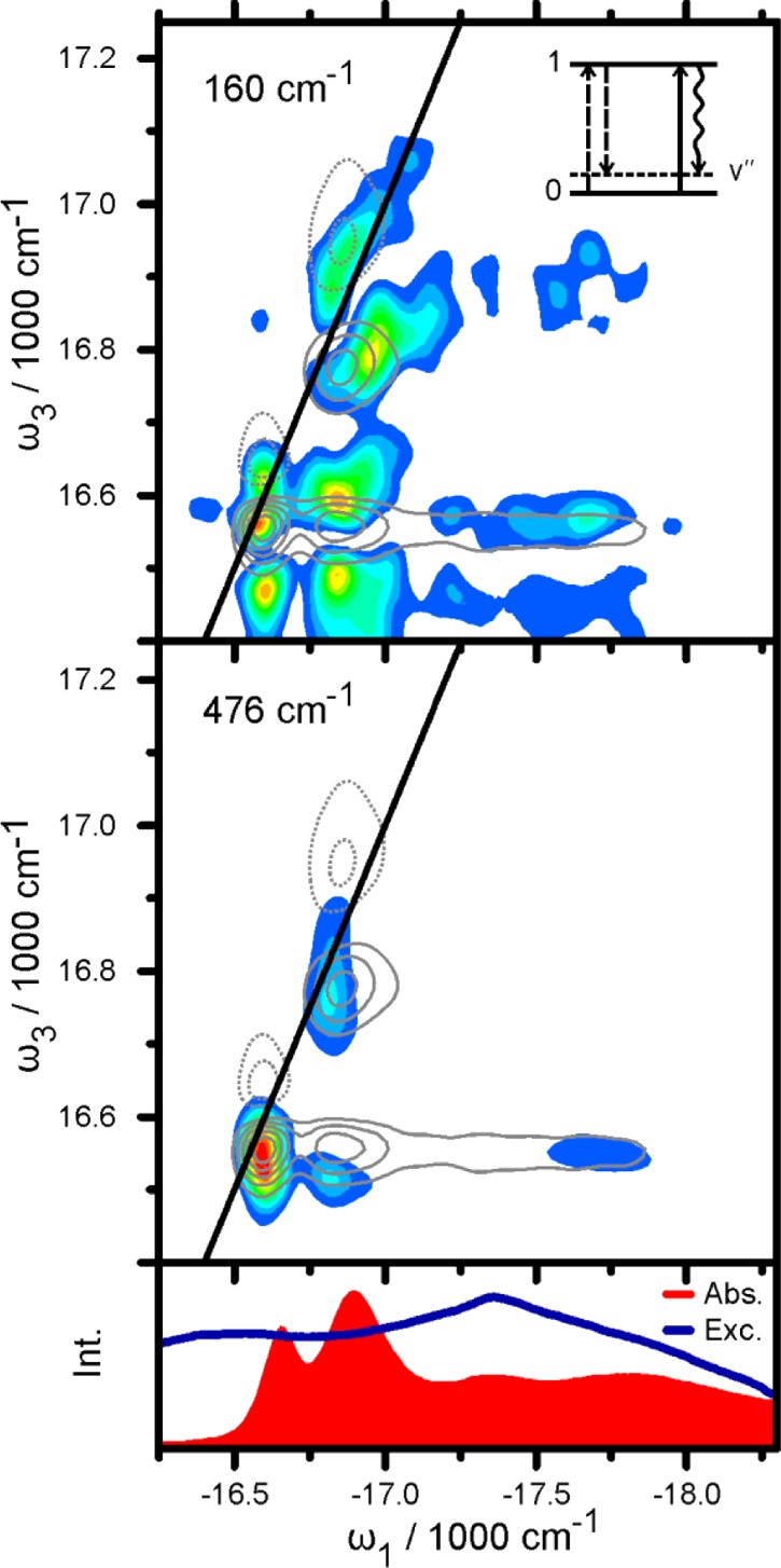
FFT-amplitude maps of the oscillatory components at 160 cm–1 (top) and 476 cm–1 (bottom). The 2D map is shown in comparison as gray contour lines with full lines (dashed lines) for positive (negative) signals (see Figure 2 for comparison). The inset in the upper panel shows an energy ladder diagram explaining the peaks at ω3 ≈ 16470 cm–1. Electronic (vibrational) levels are depicted as horizontal full (dotted) lines. Bra-side and ket-side interactions and the resulting signal are shown as dashed, full, and wavy arrows, respectively. Absorption and excitation spectrum are shown in the lower panel for comparison.
We can therefore conclude that the 160 cm–1 modulation stems from a vibrational wavepacket on the electronic ground state. This assignment cannot be confirmed by the Raman-spectra in Figure 4, due to their 200 cm–1 cutoff-energy. The 476 cm–1 modulation on the other hand exhibits a qualitatively different amplitude map. The peaks red-shifted in ω3 by one vibrational quantum at 16050 cm–1 (not shown in Figure 5) are absent. This observation in combination with the (nearly) missing peak at 476 cm–1 in the Raman spectrum excludes an assignment to a vibrational ground state mode. A purely vibrational origin in the excited state is also unlikely, given that the 476 cm–1 map in Figure 5 shows a signal at the 41-position; the corresponding oscillation as depicted in Figure 2 shows a long lifetime, while state 4 depopulates on a 150 fs time scale (see Supporting Information). In a simple system with excited state vibrations, the vibrational lifetime should not exceed the electronic lifetime. A purely electronic or excitonic character of the 476 cm–1 oscillation can also be excluded, based on the following argument: the oscillatory amplitude is strongest at peaks 11, 22, and 21. In an ideal electronic dimer,43 the oscillatory frequency should then coincide with the energy spacing between the two corresponding peaks in the absorption spectrum. This energy difference between bands 1 and 2 of only 230 cm–1 is, however, far from the expected 476 cm–1. On the basis of previously published analyses34,35,39,44−46 we conclude that the nature of the observed oscillation is most likely vibronic, i.e., resulting from an excitonic mixing between the electronic (zero phonon) excited state and weakly allowed vibrationally excited states. Signatures of such vibronic coherences originating in the excited state are similar to the electronic ones, and the frequencies of oscillations are shifted from those of pure vibrational and electronic features. Cheng and Fleming47 suggested distinguishing between electronic and vibrational oscillations based on their signatures in rephasing and nonrephasing 2D spectra. Turner et al.41 later used this approach for analyzing experimental data. Even though this method is only valid for purely electronic (i.e., three level) and purely vibrational (i.e., four level) systems, we can rule out a purely electronic character of the 476 cm–1 oscillation by analyzing rephasing and nonrephasing spectra separately, as done in the Supporting Information.
We now turn to a discussion of the overall vibrational amplitudes in relation to their position on the 2D map. By examination of the 160 cm–1 amplitude distribution in Figure 5 it becomes obvious that the oscillations for cross peaks are strong when band 4 is part of the coherence, i.e., for peaks 41 and 42. We note that the high oscillatory amplitude for peak 11 and 22 is explained by the higher number of contributing pathways for diagonal- than for cross-peaks.14,48 When describing the oscillations with a basic model of displaced harmonic oscillators, the vibrational amplitude is in first approximation determined by the Huang–Rhys factor HR = d2/2. The increase of oscillatory strength between the cross peaks 31 < 41 is therefore explained by an increase of curve displacement d3 < d4. A larger value for d4 is in agreement with the assumption that the origin of band 4 is a segment of smaller delocalization length.21 Delocalization leads to an effective decrease of the electron–phonon coupling on a delocalized state in terms of the square of the displacement d2 by a factor (1/Nk) = ΣnN|cn|4, known as inverse participation ratio.49 Here cn(k) is a coefficient of the expansion of the delocalized eigenstate ψk = Σncnφk in terms of the localized states φk. For a state delocalized equally over N chromophores, we have |cn(k)| = 1/√N and, correspondingly, 1/Nk = 1/N. For a state that is delocalized over an M times smaller segment, we therefore expect an effective HR factor M times larger.
We note that recently, Eisele et al.9 offered an alternative explanation for band 4 by showing that for C8S3 aggregates, a so-called EHB structural model for the molecular organization within the tubular layers also delivers a four-band absorption spectrum.
4. Conclusions
Using Raman spectroscopy, pump–probe, and 2D-ES, we have analyzed the energy deactivation network in a mesoscopic molecular J-aggregate. 2D-DAS analysis of the 2D spectra at different population times shows that only three time constants suffice to describe the aggregate’s intricate population dynamics. Additionally, we observe and analyze both vibrational and vibronic coherence dynamics in the system. On the basis of our results, we argue that band 4 in the aggregate’s absorption spectrum has excitonic character and may stem from a segment of shorter delocalization length.
Acknowledgments
J.H. and F.M. acknowledge funding by the Austrian Science Fund (FWF): START project Y 631-N27. H.F.K. acknowledges funding by the Austrian Science Fund (FWF): AP 22331.
Supporting Information Available
Description and results from 3D global fitting approach to recover 2D-DAS from the set of electronic 2D spectra at different population times t2. This material is available free of charge via the Internet at http://pubs.acs.org.
Author Contributions
All authors contributed equally.
The authors declare no competing financial interest.
Notes
Supplementary Material
References
- Scheibe G. Über die Veränderlichkeit der Absorptionsspektren in Lösungen Und die Nebenvalenzen als ihre Ursache. Angew. Chem. 1937, 50, 212–219. [Google Scholar]
- Würthner F.; Kaiser T. E.; Saha-Moller C. R. J-Aggregates: From Serendipitous Discovery to Supramolecular Engineering of Functional Dye Materials. Angew. Chem., Int. Ed. 2011, 50, 3376–3410. [DOI] [PubMed] [Google Scholar]
- von Berlepsch H.; Böttcher C.. The Morphologies of Molecular Cyanine Dye Aggregates as Revealed by Cryogenic Transmission Electron Microscopy. In J-Aggregates; Kobayashi T., Ed.; World Scientific: Singapore, 2012; Vol. 2; pp 119–153. [Google Scholar]
- Ganapathy S.; Oostergetel G. T.; Wawrzyniak P. K.; Reus M.; Chew A. G. M.; Buda F.; Boekema E. J.; Bryant D. A.; Holzwarth A. R.; de Groot H. J. M. Alternating Syn–Anti Bacteriochlorophylls Form Concentric Helical Nanotubes in Chlorosomes. Proc. Natl. Acad. Sci. U.S.A. 2009, 106, 8525–8530. [DOI] [PMC free article] [PubMed] [Google Scholar]
- Scholes G. D.; Fleming G. R.; Olaya-Castro A.; van Grondelle R. Lessons from Nature about Solar Light Harvesting. Nat. Chem. 2011, 3, 763–774. [DOI] [PubMed] [Google Scholar]
- von Berlepsch H.; Bottcher C.; Ouart A.; Burger C.; Dahne S.; Kirstein S. Supramolecular Structures of J-Aggregates of Carbocyanine Dyes in Solution. J. Phys. Chem. B 2000, 104, 5255–5262. [Google Scholar]
- von Berlepsch H.; Kirstein S.; Hania R.; Didraga C.; Pugzlys A.; Bottcher C. Stabilization of Individual Tubular J-Aggregates by Poly(vinyl alcohol). J. Phys. Chem. B 2003, 107, 14176–14184. [Google Scholar]
- Didraga C.; Klugkist J. A.; Knoester J. Optical Properties of Helical Cylindrical Molecular Aggregates: The Homogeneous Limit. J. Phys. Chem. B 2002, 106, 11474–11486. [Google Scholar]
- Eisele D. M.; Cone C. W.; Bloemsma E. A.; Vlaming S. M.; van der Kwaak C. G. F.; Silbey R. J.; Bawendi M. G.; Knoester J.; Rabe J. P.; Vanden Bout D. A. Utilizing Redox-Chemistry to Elucidate the Nature of Exciton Transitions in Supramolecular Dye Nanotubes. Nat. Chem. 2012, 4, 655–662. [DOI] [PubMed] [Google Scholar]
- Tauber M. J.; Mathies R. A.; Chen X. Y.; Bradforth S. E. Flowing Liquid Sample Jet for Resonance Raman and Ultrafast Optical Spectroscopy. Rev. Sci. Instrum. 2003, 74, 4958–4960. [Google Scholar]
- Laimgruber S.; Schachenmayr H.; Schmidt B.; Zinth W.; Gilch P. A Femtosecond Stimulated Raman Spectrograph for the Near Ultraviolet. Appl. Phys. B: Lasers Opt. 2006, 85, 557–564. [Google Scholar]
- Piel J.; Riedle E.; Gundlach L.; Ernstorfer R.; Eichberger R. Sub-20 fs Visible Pulses with 750 nJ Energy from a 100 KHz Noncollinear Optical Parametric Amplifier. Opt. Lett. 2006, 31, 1289–1291. [DOI] [PubMed] [Google Scholar]
- Trebino R.Frequency-Resolved Optical Gating: The Measurement of Ultrashort Laser Pulses; Kluwer Academic Publishing Group: Dordrecht, Netherlands, 2002. [Google Scholar]
- Mancal T.; Christensson N.; Lukes V.; Milota F.; Bixner O.; Kauffmann H. F.; Hauer J. System-Dependent Signatures of Electronic and Vibrational Coherences in Electronic Two-Dimensional Spectra. J. Phys. Chem. Lett. 2012, 3, 1497–1502. [DOI] [PubMed] [Google Scholar]
- Sperling J.; Nemeth A.; Hauer J.; Abramavicius D.; Mukamel S.; Kauffmann H. F.; Milota F. Excitons and Disorder in Molecular Nanotubes: A 2D Electronic Spectroscopy Study and First Comparison to a Microscopic Model. J. Phys. Chem. A 2010, 114, 8179–8189. [DOI] [PubMed] [Google Scholar]
- Nemeth A.; Sperling J.; Hauer J.; Kauffmann H. F.; Milota F. Compact Phase-Stable Design for Single- and Double-Quantum Two-Dimensional Electronic Spectroscopy. Opt. Lett. 2009, 34, 3301–3303. [DOI] [PubMed] [Google Scholar]
- Khalil M.; Demirdoven N.; Tokmakoff A.. Obtaining Absorptive Line Shapes in Two-Dimensional Infrared Vibrational Correlation Spectra, Phys. Rev. Lett. 2003, 90 [DOI] [PubMed] [Google Scholar]
- Hybl J. D.; Albrecht A. W.; Faeder S. M. G.; Jonas D. M. Two-Dimensional Electronic Spectroscopy. Chem. Phys. Lett. 1998, 297, 307–313. [Google Scholar]
- Bednarz M.; Knoester J. The Linear Absorption and Pump–Probe Spectra of Cylindrical Molecular Aggregates. J. Phys. Chem. B 2001, 105, 12913–12923. [Google Scholar]
- Lampoura S. S.; Spitz C.; Dahne S.; Knoester J.; Duppen K. The Optical Dynamics of Excitons in Cylindrical J-Aggregates. J. Phys. Chem. B 2002, 106, 3103–3111. [Google Scholar]
- Pugzlys A.; Hania P. R.; Augulis R.; Duppen K.; van Loosdrecht P. H. M. Cylindrical Aggregates of 5,5′,6,6′-Tetrachlorobenzimidacarbocyanine Amphiphilic Derivatives: Structure-Related Optical Properties and Exciton Dynamics. Int. J. Photoenergy 2006, 29623. [Google Scholar]
- Brixner T.; Mancal T.; Stiopkin I. V.; Fleming G. R. Phase-Stabilized Two-Dimensional Electronic Spectroscopy. J. Chem. Phys. 2004, 121, 4221–4236. [DOI] [PubMed] [Google Scholar]
- Didraga C.; Pugzlys A.; Hania P. R.; von Berlepsch H.; Duppen K.; Knoester J. Structure, Spectroscopy, and Microscopic Model of Tubular Carbocyanine Dye Aggregates. J. Phys. Chem. B 2004, 108, 14976–14985. [Google Scholar]
- Spitz C.; Knoester J.; Ouart A.; Daehne S. Polarized Absorption and Anomalous Temperature Dependence of Fluorescence Depolarization in Cylindrical J-Aggregates. Chem. Phys. 2002, 275, 271–284. [Google Scholar]
- Nemeth A.; Milota F.; Sperling J.; Abramavicius D.; Mukamel S.; Kauffmann H. F. Tracing Exciton Dynamics in Molecular Nanotubes with 2D Electronic Spectroscopy. Chem. Phys. Lett. 2009, 469, 130–134. [Google Scholar]
- Dijkstra A. G.; Jansen T. L. C.; Knoester J.. Localization and Coherent Dynamics of Excitons in the Two-Dimensional Optical Spectrum of Molecular J-Aggregates, J. Chem. Phys. 2008, 128 [DOI] [PubMed] [Google Scholar]
- Womick J. M.; Miller S. A.; Moran A. M. Probing the Dynamics of Intraband Electronic Coherences in Cylindrical Molecular Aggregates. J. Phys. Chem. A 2009, 113, 6587–6598. [DOI] [PubMed] [Google Scholar]
- Womick J. M.; Miller S. A.; Moran A. M. Correlated Exciton Fluctuations in Cylindrical Molecular Aggregates. J. Phys. Chem. B 2009, 113, 6630–6639. [DOI] [PubMed] [Google Scholar]
- Milota F.; Sperling J.; Nemeth A.; Abramavicius D.; Mukamel S.; Kauffmann H. F. Excitonic Couplings and Interband Energy Transfer in a Double-Wall Molecular Aggregate Imaged by Coherent Two-Dimensional Electronic Spectroscopy. J. Chem. Phys. 2009, 131, 054510. [DOI] [PubMed] [Google Scholar]
- Milota F.; Sperling J.; Nemeth A.; Kauffmann H. F. Two-Dimensional Electronic Photon Echoes of a Double Band J-Aggregate: Quantum Oscillatory Motion Versus Exciton Relaxation. Chem. Phys. 2009, 357, 45–53. [Google Scholar]
- Stiopkin I.; Brixner T.; Yang M.; Fleming G. R. Heterogeneous Exciton Dynamics Revealed by Two-Dimensional Optical Spectroscopy. J. Phys. Chem. B 2006, 110, 20032–20037. [DOI] [PubMed] [Google Scholar]
- Nemeth A.; Lukes V.; Sperling J.; Milota F.; Kauffmann H. F.; Mancal T. Two-Dimensional Electronic Spectra of an Aggregating Dye: Simultaneous Measurement of Monomeric and Dimeric Line-Shapes. Phys. Chem. Chem. Phys. 2009, 11, 5986–5997. [DOI] [PubMed] [Google Scholar]
- Myers J. A.; Lewis K. L. M.; Fuller F. D.; Tekavec P. F.; Yocum C. F.; Ogilvie J. P. Two-Dimensional Electronic Spectroscopy of the D1-D2-Cyt B559 Photosystem II Reaction Center Complex. J. Phys. Chem. Lett. 2010, 1, 2774–2780. [Google Scholar]
- Chenu A.; Christensson N.; Kauffmann H. F.; Mancal T. Enhancement of Vibronic and Ground-State Vibrational Coherences in 2D Spectra of Photosynthetic Complexes. arXiv.org, e-Print arch., Chem. Phys. 2012, arXiv:1211.4397. [DOI] [PMC free article] [PubMed] [Google Scholar]
- Christensson N.; Kauffmann H. F.; Pullerits T.; Mancal T. Origin of Long-Lived Coherences in Light-Harvesting Complexes. J. Phys. Chem. B 2012, 116, 7449–7454. [DOI] [PMC free article] [PubMed] [Google Scholar]
- Christensson N.; Milota F.; Hauer J.; Sperling J.; Bixner O.; Nemeth A.; Kauffmann H. F. High Frequency Vibrational Modulations in Two-Dimensional Electronic Spectra and Their Resemblance to Electronic Coherence Signatures. J. Phys. Chem. B 2011, 115, 5383–5391. [DOI] [PubMed] [Google Scholar]
- Turner D. B.; Wilk K. E.; Curmi P. M. G.; Scholes G. D. Comparison of Electronic and Vibrational Coherence Measured by Two-Dimensional Electronic Spectroscopy. J. Phys. Chem. Lett. 2011, 2, 1904–1911. [Google Scholar]
- Coles D. M.; Meijer A. J. H. M.; Tsoi W. C.; Charlton M. D. B.; Kim J. S.; Lidzey D. G. A Characterization of the Raman Modes in a J-Aggregate-Forming Dye: A Comparison between Theory and Experiment. J. Phys. Chem. A 2010, 114, 11920–11927. [DOI] [PubMed] [Google Scholar]
- Aydin M.; Dede O.; Akins D. L. Density Functional Theory and Raman Spectroscopy Applied to Structure and Vibrational Mode Analysis of 1,1′,3,3′-Tetraethyl-5,5′,6,6′-Tetrachloro-Benzimidazolocarbocyanine Iodide and Its Aggregate. J. Chem. Phys. 2011, 134, 064325. [DOI] [PubMed] [Google Scholar]
- Engel G. S.; Calhoun T. R.; Read E. L.; Ahn T.-K.; Mancal T.; Cheng Y.-C.; Blankenship R. E.; Fleming G. R. Evidence for Wavelike Energy Transfer through Quantum Coherence in Photosynthetic Systems. Nature 2007, 446, 782–786. [DOI] [PubMed] [Google Scholar]
- Turner D. B.; Dinshaw R.; Lee K.-K.; Belsley M. S.; Wilk K. E.; Curmi P. M. G.; Scholes G. D. Quantitative Investigations of Quantum Coherence for a Light-Harvesting Protein at Conditions Simulating Photosynthesis. Phys. Chem. Chem. Phys. 2012, 14, 4857–4874. [DOI] [PubMed] [Google Scholar]
- Panitchayangkoon G.; Voronine D. V.; Abramavicius D.; Caram J. R.; Lewis N. H. C.; Mukamel S.; Engel G. S. Direct Evidence of Quantum Transport in Photosynthetic Light-Harvesting Complexes. Proc. Natl. Acad. Sci. U.S.A. 2011, 108, 20908–20912. [DOI] [PMC free article] [PubMed] [Google Scholar]
- Butkus V.; Zigmantas D.; Valkunas L.; Abramavicius D. Vibrational vs. Electronic Coherences in 2D Spectrum of Molecular Systems. Chem. Phys. Lett. 2012, 545, 40–43. [Google Scholar]
- Tiwari V.; Peters W. K.; Jonas D. M. Electronic Resonance with Anticorrelated Pigment Vibrations Drives Photosynthetic Energy Transfer Outside the Adiabatic Framework. Proc. Natl. Acad. Sci. U.S.A. 2012, 10.1073/pnas.1211157110. [DOI] [PMC free article] [PubMed] [Google Scholar]
- Womick J. M.; Moran A. M. Vibronic Enhancement of Exciton Sizes and Energy Transport in Photosynthetic Complexes. J. Phys. Chem. B 2011, 115, 1347–1356. [DOI] [PubMed] [Google Scholar]
- West B. A.; Womick J. M.; McNeil L. E.; Tan K. J.; Moran A. M. Influence of Vibronic Coupling on Band Structure and Exciton Self-Trapping in α-Perylene. J. Phys. Chem. B 2011, 115, 5157–5167. [DOI] [PubMed] [Google Scholar]
- Cheng Y. C.; Fleming G. R. Coherence Quantum Beats in Two-Dimensional Electronic Spectroscopy. J. Phys. Chem. A 2008, 112, 4254–4260. [DOI] [PubMed] [Google Scholar]
- Farrow D. A.; Smith E. R.; Qian W.; Jonas D. M. The Polarization Anisotropy of Vibrational Quantum Beats in Resonant Pump–Probe Experiments: Diagrammatic Calculations for Square Symmetric Molecules. J. Chem. Phys. 2008, 129, 174509. [DOI] [PubMed] [Google Scholar]
- Cho M. H.; Vaswani H. M.; Brixner T.; Stenger J.; Fleming G. R. Exciton Analysis in 2D Electronic Spectroscopy. J. Phys. Chem. B 2005, 109, 10542–10556. [DOI] [PubMed] [Google Scholar]
Associated Data
This section collects any data citations, data availability statements, or supplementary materials included in this article.


