Abstract
The capability to perform multicolor, wide field-of-view (FOV) fluorescence microscopy imaging is important in screening and pathology applications. We developed a microscopic slide-imaging system that can achieve multicolor, wide FOV, fluorescence imaging based on the Talbot effect. In this system, a light-spot grid generated by the Talbot effect illuminates the sample. By tilting the excitation beam, the Talbot-focused spot scans across the sample. The images are reconstructed by collecting the fluorescence emissions that correspond to each focused spot with a relay optics arrangement. The prototype system achieved an FOV of 12 × 10 mm2 at an acquisition time as fast as 23 s for one fluorescence channel. The resolution is fundamentally limited by spot size, with a demonstrated full-width at half-maximum spot diameter of 1.2 μm. The prototype was used to image green fluorescent beads, double-stained human breast cancer SK-BR-3 cells, Giardia lamblia cysts, and the Cryptosporidium parvum oocysts. This imaging method is scalable and simple for implementation of high-speed wide FOV fluorescence microscopy.
OCIS codes: (180.2520) Fluorescence microscopy, (110.6760) Talbot and self-imaging effects
1. Introduction
Due to the high sensitivity of fluorescent probes, fluorescence microscopy plays a vital role in modern clinical diagnosis and biological research. Fluorescent probes can bind to target proteins with high specificity, and multicolor fluorescence microscope enables the simultaneous visualization of multiple protein interactions in living cells [1]. Multicolor fluorescent staining also provides higher contrast for tissue imaging [2] and reveals neuronal subsets in small animal [3]. In many fluorescence microscopy applications, a large field-of-view (FOV) is often desired.
As the dominant instrument in these applications, the conventional fluorescence microscope is limited by its FOV. The most common method for increasing the FOV of a fluorescence microscope would be to raster-step the sample under a conventional microscope objective [4]. The microscope would take limited FOV (dimensions given by the FOV of the objective) images at each step-stop and assemble a complete image at the end. Using this method, the time spent on the step motion and focus readjustment is generally longer than the imaging. Recently, state-of-the-art commercialized slide scanners have begun to employ time-delayed integration cameras, so that a continuous scan can be applied in one scan direction, whereas the step movement is still required in the other direction [5]. This modification can reduce the full-field imaging time by reducing the total number of step-stops required.
To address this speed limitation, there have been a number of published studies that have explored the prospect of using point-scan methods in place of a conventional microscope to accomplish wide FOV fluorescence imaging [6–10]. Using these methods, a grid of focused spots is generated by a grid of microlenses [6, 7, 10], a diffractive optical element [11], or a hologram plate [8]. The dimension of the focused spot grid can be designed to be much larger than the FOV of a microscope objective (< 1 mm); it is even possible to create a spot grid that is larger than the dimensions of standard microscope slides (~15 mm). As the sample is transported by a mechanical stage, the focused spot grid scans across the sample, and a relay optics system collects the fluorescent emissions from each focused spot. These data can be reconstituted to form large FOV and high-resolution (resolution equal to focused spot size) images. Such methods allow speed improvements based on two principles. First, such methods require the sample to physically translate over a much shorter distance and thereby allow the use of faster mechanical translators with shorter travel range. More explicitly, conventional methods require the sample to translate over a distance approximately equal to the dimension of the target FOV (typically ~1 cm); a point-scan method only requires sample translations that are equal to the pitch of the focused spots (typically < 100 microns). The second key difference between the methods lies in the fact that the total number of image points that can be collected at any given time point is equal to the number of focused spots or the number of camera pixels in the point-scan approach. In comparison, for a conventional system, the total number of image points that can be simultaneously imaged is equal to the total number of resolvable points available through the microscope objective. In other words, the point-scan methods are amenable to speed improvements using more focused spots without physical optics limitations.
All of the abovementioned methods involve mechanical sample translation rather than focused spot translation. The shifting of a light-field pattern (in this case, the focused spot grid) has the intrinsic advantage of eliminating the prospect of physically translating the sample. However, none of the abovementioned methods lends itself well to such optical translation. For example, one can consider translating the focused spot grid by angularly tilting the input light field to the microlens grid, diffractive optical element, or hologram plate, as a means for accomplishing such optical translation. However, the requisite angular tilt required would invariably introduce significant distortions to the focused spots and thereby degrade the achievable resolution.
Our recent works with focused spot-grid scanning based on the Talbot effect for wide FOV imaging [9, 12, 13] can address this issue. In brief, rather than using the focused spot grid directly as generated by a microlens grid for point-scanning microscopy, we used the reformed, focused spot grid at a Talbot distance from the original focused spot grid [9, 12, 13]. The use of the Talbot effect provides a long working distance for easy sample mounting and generates more uniform intensities among focused spots [14]. More importantly, it allows the translation of the focused spot grid for point-scanning microscopy without significant aberrations [12, 13]. We recently employed this approach to perform chip-scale fluorescence imaging—we term this class of microscopy, Talbot microscopy [12, 13]. In these Talbot microscopy systems, the sample was directly placed on an imaging sensor. However, the mounting of samples onto a sensor chip is not a standard laboratory preparation procedure, and it is challenging to image the fluorescent sample with multiple staining, due to the limitations of the transmission spectrum of the fixed on-chip filter [15].
In this paper, we report a multicolor fluorescence Talbot microscopy (multicolor FTM) system that is able to perform multicolor fluorescence microscopy imaging. This system also represents a departure from the original chip-scale Talbot microscopy implementation [12,13] and is capable of working with samples that are mounted on standard glass slides. This system achieved a large FOV of 12 mm × 10 mm at a resolution of 1.2 μm, with the imaging time as fast as 23 s for full FOV imaging.
This paper first reviews the operating principle of the Talbot microscope. Next, the paper reports the implementation of our prototype multicolor FTM system and quantifies its resolution and imaging depth. The manuscript also reports the results from using the system to image the double-stained SK-BR-3 cancer cells. We also demonstrate the system’s potential application in the screening of enteric parasites by imaging two fluorescently labeled, encysted, protozoan parasites: Giardia lamblia and Cryptosporidium parvum. Finally, the manuscript discusses the advantages and limitations of the system.
2. System design
2.1 Talbot microscopy principle review
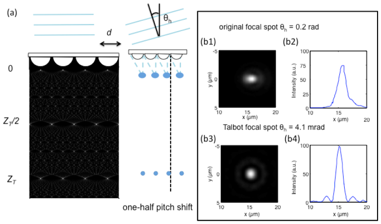
In a confocal microscopy setup, angle scanning is generally preferred over a translational stage because of the improved stability and speed [16]. However, an angular scanning scheme for a large tilt angle is problematic due to off-axis aberrations. In a typical microscope, the field angle is usually less than 4°. This means that to preserve the quality of the focused spot, the tilt angle in the conventional microscope should not exceed 2° [17]. In the scanning scheme using a microlens grid, the focused spot grid must shift one-half pitch of the microlens grid to perform the whole-area scan. For a typical microlens grid with 30-μm pitch and a focused length of 70 μm, the half-pitch tilt angle, θh, is 12° (0.21 rad). At this tilt angle, the focused spot is significantly distorted by off-axis aberrations. Figure 1 (b1) and 1(b2) shows the scalar wave simulation of the point-spread function (PSF) of the focused spot when it is shifted by one-half pitch. From the results, we can see that the full width at half maximum (FWHM) of the focused spot along the shift direction was 1.8 μm, compared with 1.2 μm under the normal incident beam. This illustrates that employing optical scanning for wide FOV microscopy imaging is non-trivial.
Fig. 1.
Comparison between scanning with an original focused grid and with a Talbot-focused grid. (a) By tilting the incident beam angle, the original focused spots generated by the microlens grid as well as the Talbot-focused spots can be shifted for scanning. (b) Simulated focused spot intensity profiles at the tilt angle of one-half pitch shift are 15 µm in this case. The angle needed for an one-half pitch shift for original focused spot is 0.2 radian, and the focused spot was affected by off-axis aberrations (b1 and b2). The angle needed for one-half pitch shift for the Talbot-focused spot is 0.0041 radian, and the focused spot maintains good quality (b3 and b4).
The Talbot microscope solves this problem by using the reformed, focused spot grid generated by the Talbot effect. In brief, the Talbot effect is a self-imaging phenomenon of a periodic pattern in which the diffraction pattern of a two-dimensional periodic structure with period d under coherent planar illumination of wavelength λ creates copies of the input pattern at multiples of the Talbot distance z = nZT, where
| (1) |
ZT is called the Talbot distance. Figure 1(a) shows a simulation of the light propagation along the Z direction.
The reformed, focused spot grid at Talbot distance (Talbot-focused spot grid) translates a significant amount in response to a small angular tilt of the input light field [18, 19]. Mathematically, the translation, Δ, versus angular tilt, θ, is given by:
| (2) |
The required angle tilt θ = λ/4d for the Talbot spot to move one-half pitch is d/2. For the microlens grid with the parameters mentioned above, the tilt angle is only 4.1 mrad, which is 50 times smaller than the tilt angle needed to translate the original focused spots. With this small tilt angle, the original focused spot maintains a sharp focus, and the Talbot-focused spot is not significantly affected by off-axis aberrations. Figure 1(b3) and 1(b4) shows the PSF of the Talbot-focused spot under the shift. The simulation results showed that the FWHM of the Talbot-focused spot is 1.3 μm, which illustrates the applicability of the Talbot-focused spot grid to facilitate wide FOV imaging with optical scanning.
More specifically, to perform Talbot-focused spot scanning, we only need to tilt the incident input beam to the microlens grid. The sample is placed at the Talbot distance. As the Talbot-focused spot grid scans across the sample, the locally excited fluorescence can be collected, and the full FOV image is reconstructed.
2.2. System setup
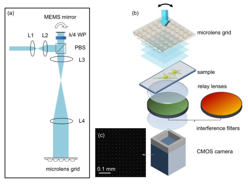
Figure 2(a) shows the setup for generating the Talbot-focused spot grid. A 488-nm laser (Newport Cyan 100mW) was expanded by a telescope system. Two plano-convex lenses, L1 (Thorlabs, f1 = 25.4 mm) and L2 (Thorlabs, f2 = 125 mm), expanded the beam approximately 5 times to fill the aperture of the microelectromechanical system (MEMS) mirror (Mirrocle, 5.0-mm diameter). A polarization-sensitive beam splitter (PBS, Thorlabs) directed the beam to the MEMS mirror.
Fig. 2.
The system setup for the Talbot microscope. (a) The optical setup for generating an angular shift incident beam to the microlens grid. L1 (f = 25.4 mm) and L2 (f = 125 mm) expand the beam to fit the MEMS mirror diameter. After the beam passes through the PBS and the λ/4 WP (one-quarter wave plate), the beam was further expanded by L3 (f = 50 mm) and L4 (f = 400 mm). (b) The system setup for the sample and detection: The sample was placed at one Talbot distance away from the focused grid generated by the microlens grid, and two SLR camera lenses formed a 1:1 relay system to collect the fluorescence signal. The optical filters were inserted between the relay lenses. (c) A small area of Talbot-focused spot grid imaged by the CMOS camera without the bandpass filter.
A one-quarter wave plate was inserted between the MEMS mirror and the PBS. The one-quarter wave plate transformed the linear polarized beam to a circular polarized beam. The beam reflected by the mirror altered the rotation direction of the circular polarized beam, and the one-quarter wave plate converted the beam to a linear polarized beam with the polarization orthogonal to the original beam. This polarization change allowed the beam to pass through the PBS, and the beam was further expanded by two lenses, L3 (Thorlabs, f = 50 mm) and L4 (Thorlabs, f = 400 mm), which was incident on the microlens grid (Suss MicroOptics, pitch 30 μm). To perform wide FOV imaging, we used a large microlens grid with an area of 40 × 40 mm2. This secondary expansion made the final incident beam diameter approximately 40 mm. The MEMS mirror was placed on the front focal plane of L3, and the microlens grid was placed on the back focal plane of L4. Because the MEMS mirror and the microlens grid were on the conjugate planes, the tilt of the MEMS mirror would only change the incident angle to the microlens grid but would not induce a beam shift on the microlens grid.
Figure 2(b) shows the system setup for fluorescence excitation and collection. The sample on the microscope slide was placed at one Talbot distance away from the microlens grid-focused spot. To collect the fluorescent emissions from the sample, two single-lens reflex (SLR) camera lenses served as a 1:1 relay system (Nikon Nikkor 50 mm f/1.2). The collection efficiency of the SLR camera lenses was equivalent to 0.4 N.A. The CMOS camera (Teledyne DALSA, Falcon2 4M) has a pixel size of 6 μm.
Based on the Nyquist sampling criterion, the resolution on the collection side was only 12 μm. However, this parameter is irrelevant to the achievable resolution of our multicolor FTM system, as its resolution is solely dependent on the focused spot size. The collection side resolution is, however, relevant in limiting the useful pitch of the focused spot grid: If the pitch of the focused spot grid were smaller than the collection side resolution, it would be impossible to discern fluorescence signals associated with adjacent focused spots.
The separation between the two SLR camera lenses afforded us space to insert and exchange optical filters as needed for multicolor fluorescence imaging.
Figure 2(c) shows a portion of the Talbot focused spot grid as imaged by the camera. The variations in the imaged spots is attributable to the fact that some of the focused spots are incident on two adjacent pixels which lead to broad and dimmer spots, while some of the spots are incident on a single pixel which lead to sharp and bright spots. By summing up the total pixel values associate to a focal spot, we find that the unevenness in neighboring spots intensity is less than 4%. We also quantified the unevenness of Talbot spots over an area of 1mm by 1mm. The standard deviation of 6 randomly picked spots is 4.73%.
The imaging area of the CMOS camera is 14 × 10 mm2, which determined the system FOV. An important design difference between this multicolor FTM and the original chip-based FTM is that the FOV of the original chip-based FTM design can be scaled up without restriction by simply using a larger focused spot grid and a larger sensor (with a tandem increase in input laser power). In contrast, the inclusion of collection side optics in this current multicolor FTM imposes an FOV limitation. Specifically, the FOV can only be scaled (using a larger focused spot grid and larger camera) up to the point at which aberration-induced resolution deterioration at the edges of the image formed at the camera exceeds the pitch of the focused spot grid. In our prototype, this works out to an FOV limit of approximately 50 mm. This limitation can be mitigated using collection side optics with better aberration correction; although such optics may restrict the collection N.A. and lead to less-efficient fluorescence signal collection.
Overall, the multicolor fluorescence imaging capability and ability to work with samples on standard glass slides are highly desirable advantageous multicolor FTM features suitable for general applications that are worth the price of an upper FOV limit.
3. Results and discussion
3.1 Image resolution
The resolution of the system can be quantified by measuring the PSF of the Talbot-focused spot. We used a multicolor FTM system to image 200-nm green fluorescent microspheres (Life Technologies, FluoSpheres® 0.2 µm). The step size of the scan was set at 0.31 μm. Figure 3(c) and 3(d) shows the measured lateral profiles of the resolution. The lateral intensity profile was fit to Gaussian functions, and the FWHMs were measured as 1.20 μm and 1.21 μm along the horizontal and vertical directions, respectively.
Fig. 3.
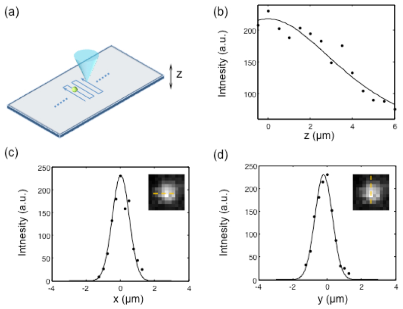
Resolution of the system. (a) The point spread function of the Talbot-focused spot was measured by scanning a 200-nm fluorescence bead. (b) The z profile of the Talbot-focused spot, (c) the x profile of the Talbot-focused spot, and (d) the y profile. The insets in (c) and (d) are the images of the 200-nm fluorescence bead.
We also measured the focal depth along the axial direction. The microsphere sample was placed on a translational stage with a step motor (Newport, ESP0001), and the sample was vertically moved with a step size of 1 μm. Figure 3(b) shows the z profile measurement.
Assuming the Talbot-focused spot that propagates along the axis has a Gaussian beam profile, we fit the z profile with the following equation:
| (3) |
where I0 is the central intensity of the Talbot-focused spot and zr is the one-half focal depth of the beam. The experimentally measured focal depth was 9.7 μm.
Using the measured lateral profile of the focus, we can also calculate the depth of the focus using the beam width ω0 with Eq. (4).
| (4) |
The calculated focal depth is 12.8 μm, which is close to the experimental results. The difference can be attributed to the relay system. The camera lens relay system has an N.A. of 0.4, which can also provide a degree of optical sectioning. However, the relay system did not serve as a direct fluorescence imaging system; as such, the focal depth limit should not be calculated by λ/(N.A.)2. The camera collected the fluorescence spread to an area of 4 × 4 pixels (24 μm × 24 μm). The focal depth limit calculated from the geometric optics is 24 μm/(N.A.) = 60 μm. This depth is much larger than the focal depth provided by the Talbot-focused spot. As a result, the system focal depth was primarily determined by the focal depth of the Talbot spot, but we can expect a narrowing of the focal depth by the weak optical sectioning effect of the relay system. The experimentally measured result is consistent with this expectation.
3.2 Full FOV image of green fluorescence microspheres
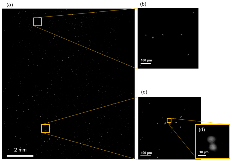
We utilized the system to image green fluorescence microspheres (Bangs Laboratories, DG06M, 8-μm diameter). To satisfy the Nyquist criterion, the step size was chosen as 0.60 μm. The number of scan steps was 56 along one direction. The extra six steps provided an overlap region between the adjacent tiles. Each tile had 56 × 56 = 3156 pixels. With approximately 40 nW on each focused spot, the dwell time for each pixel was set at 7 ms to collect a significant fluorescence signal. The imaging speed was limited by the frame rate of 140 frames per second. The full-field imaging time was 23 s. The full-field image was reconstructed from 410 × 330 Talbot-focused spots, and the reconstructed image contained 20,500 × 16,500 pixels. The image was reconstructed using Matlab. The reconstruction time was 7 minutes on a 64-bit Windows 7 personal computer with an Intel Xeon® 2.5 GHz CPU and 36 GB memory. This reconstruction time is by no means optimal; we can expect a mature system to perform the processing at a much faster rate.
Figure 4 shows the full FOV image. The full FOV was 12 mm × 10 mm.
Fig. 4.
The image of the fluorescence microsphere. (a) The full field-of-view (FOV) image of 8-µm microspheres. (b and c) The enlarged views of two 0.55 mm × 0.55 mm microspheres. (d) A further enlarged view to show two microspheres next to each other.
3.3 Multicolor fluorescence imaging of human breast cancer cell line
Compared with the system described in [13], the multicolor FTM prototype provided the flexibility of imaging multiple fluorescence colors. Here, we demonstrate the multicolor fluorescence imaging capability by imaging labeled human breast cancer SK-BR-3 cells (ATCC). The SK-BR-3 cell line has human epidermal growth factor receptor 2 (HER2) on the membrane, which was labeled by Alexa Fluor® 488. The cell nuclei were labeled by propidium iodide (PI). Both fluorescent probes can be excited by a 488-nm laser line.
The cells were fixed with 4% formaldehyde for 5 min, and incubated sequentially with mouse anti-HER2 (c-erbB-2) antibody (Life Technologies, 187107) for 1 h and 5 nM Alexa Fluor® 488 goat F(ab')2 anti-mouse IgG conjugate (Life Technologies, A10684) for 1 h, and washed with Dulbecco’s phosphate-buffered saline (Life Technologies). The sample was incubated with 500 nM PI (Life Technologies, P3566) in 2 × SCC solution (0.3 M NaCl, 0.03 M sodium citrate, pH 7.0) for 10 minutes at 37°C.
A green bandpass filter (Edmund Optics, 86-627) was used to image the HER2 marker on the cell membrane. The pixel dwell time was 40 ms. A red bandpass filter (Edmund Optics, 87-011) was used to image the cell nuclei stained by PI. The pixel dwell time was 30 ms. The total scan time for two channels was approximately 200 s. It is possible to reduce the scan time by employing a higher-power laser.
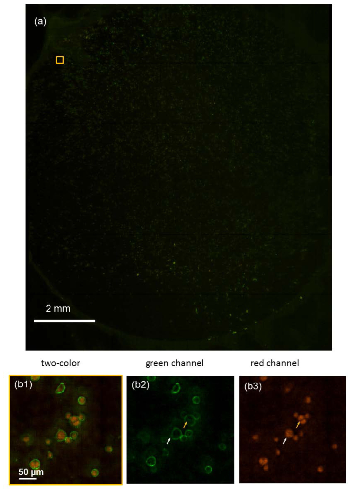
The two channels were combined to generate the double color image. Figure 5 shows the full FOV images of the double-stained SK-BR-3 cells. We can clearly distinguish the cell membranes and cell nuclei.
Fig. 5.
Fluorescent images of human breast cancer SK-BR-3 cells. The cell membrane marker Her2 was stained with Alexafluor 488 (green), and the cell nucleus was stained with PI (red). (a) The full FOV image. (b1) The enlarged view of the region indicated in (a). (b2) The green channel. (b3) The red channel.
In Fig. 5(b2) and 5(b3), we can clearly see that the cell indicated by the yellow arrow is in mitosis. The cell nucleus has divided. The cell indicated by the white arrow had a similar membrane morphology. By examining the PI channel, we could see that the cell had one nucleus and had not reached mitosis.
3.4 Multicolor fluorescence imaging of enteric parasites
We further demonstrated the imaging of Giardia lamblia cysts and Cryptosporidium parvum oocytes with our multicolor FTM prototype.
Giardia and Cryptosporidium are protozoan parasites present in untreated water sources. These parasites infect the human host by establishing an enteric infection that can cause acute gastroenteritis, with diarrhea, low-grade fever, and weight loss. The parasites pose a public health risk, since they can cause major outbreaks through contamination of the drinking water supply. Infected humans or animals shed high number of cysts of these parasites. Monoclonal antibodies are ideally suited for detection of the parasites, as they are specific to the organism. We can recognize antigens expressed on cysts/oocysts using fluorescently labeled secondary antibodies.
G. lamblia cysts, obtained from an in vitro culture of trophozoites [20], and C. parvum oocysts (Excelsior Sentinel, Inc.) were first incubated with blocking buffer (10% goat serum, 1% bovine serum albumin, 100 mM glycine, and 0.05% sodium azide in phosphate-buffered saline for 1 h, followed by incubation with anti-G. lamblia cyst (Thermo Scientific Pierce, MA1-7741) or anti-C. parvum oocyst (MyBioSource, MBS320286) antibodies. After two washes, secondary F(ab’)2 fragment goat anti-mouse IgG labeled with either Alexa Fluor® 488 (Life Technologies, A10684) or Qdot® 625 (Life Technologies, A10195) was added for 1 h and washed.
To increase the fluorescence signal from the sample, we increased the excitation intensity of each focused spot to approximately 0.6 μW by reducing the incident beam diameter to 10 mm. To ensure the uniformity of the intensities of the focused spots, we reduced the FOV to 4 mm × 4 mm. The pixel dwell time for each pixel was 80 ms. This reduction of the FOV is attributable to the limited laser power available in our experiment. A laser with higher intensity could be used for the experiment.
Figure 6 shows the fluorescence image of a mixture of G. lamblia cysts labeled with Alexa Fluor® 488 and C. parvum oocysts labeled with Qdot® 625. The fluorescence image taken by the Talbot microscope is comparable with the 20 × fluorescence microscope. The locations of some of the Cryptosporidium in the Talbot microscope slightly differed from those in the conventional microscope. This was due to perturbations of the sample while switching between the two imaging systems.
Fig. 6.
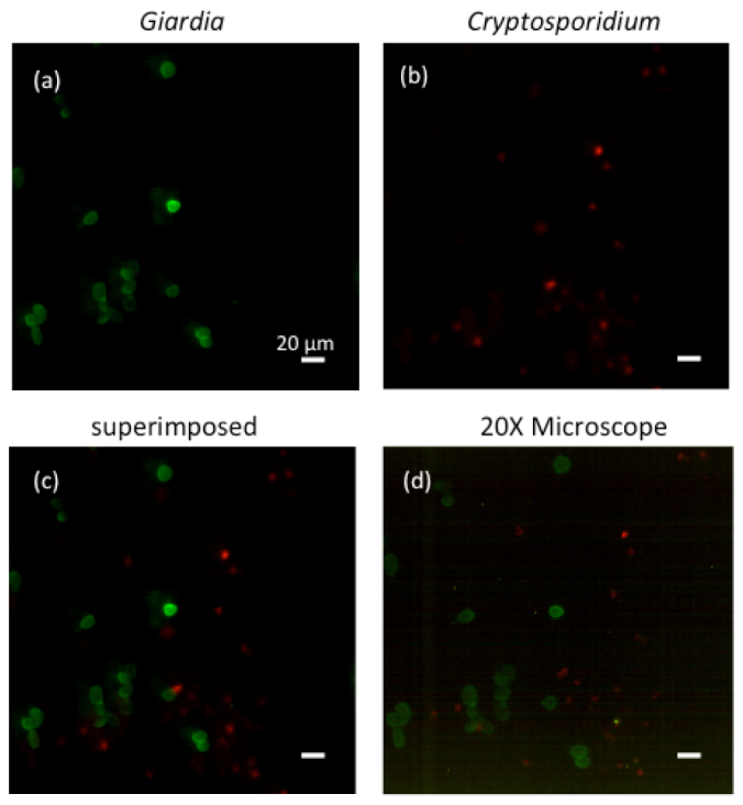
The fluorescent image of a mixture of Giardia lamblia cysts labeled with Alexa Fluor® 488 and Cryptosporidum parvum oocysts labeled with Qdot® 625. (a) The green channel shows the Giardia lamblia cysts. (b) The red channel shows the Cryptosporidum parvum oocysts. (c) The superimposed image taken by the system. (d) The 20 × fluorescence microscope image of the same area.
In the abovementioned multicolor fluorescence experiment, one excitation wavelength excited two different fluorophores. The system could also be adjusted for the use of multiple laser beams to image fluorophores with different excitation wavelengths. Because Talbot distance is a function of the wavelength, the Talbot distance varies for different wavelength excitations. A translational stage is needed to adjust the sample to accommodate this effect.
For the imaging of the microsphere sample, the imaging speed is limited by the electronic readout speed. In the double-color fluorescence imaging experiment, the low fluorescence signal level limits the imaging speed. Due to the large FOV, the excitation intensity of each Talbot spot is very low, which is only approximately 10−5 mW. A higher-power laser can be used to improve the imaging speed. We would like to point out that for dim sample imaging, the key to improvements in the imaging speed is to increase collection efficiency. The current system has a collection N.A. of 0.4. A higher N.A. collection system can be employed to improve fluorescence collection and, thereby, improve imaging speed.
The current multicolor FTM resolution is adequate for a wide range of biological applications. However, we believe that the resolution can be further improved. Although employing a microlens grid that has a higher N.A. may appear to be a reasonable solution, it is actually an approach with diminishing returns. The Talbot self-imaging effect is a paraxial optical approximation [21], which implies that the Talbot image is unable to faithfully regenerate the focused grid when the focused spot size is comparable to the optical wavelength.
A specially designed diffractive optical element is a potentially attractive way to achieve higher resolution [11]. Another promising way to achieve further resolution improvements is to redesign the refractive microlens surface so that the large angle (high spatial angular frequency) field projections can correctly “phase in” at the Talbot length to generate more tightly focused spots.
4. Conclusion
We have developed a multicolor FTM prototype based on the Talbot effect that can achieve wide FOV, multicolor fluorescence imaging of samples prepped on glass slides. The prototype system has achieved an FOV of 12 × 10 mm2 at a resolution of 1.2 μm. The acquisition time can be as fast as 23 s for one fluorescence channel. We demonstrated the imaging of green fluorescent beads and double-stained human breast cancer SK-BR-3 cells. We also applied the system to image two protozoan parasites, Giardia and Cryptosporidium, which showed its potential in enteric parasite screening. We expect that this system can be applied in wide FOV screening and sensing applications.
Acknowledgments
We thank Hao Yuan Kueh (Division of Biology, Caltech) for helpful discussions on large-FOV imaging based on conventional microscopy. This project was funded by the NIH under grant 1R01AI096226-01.
References and links
- 1.Hu C.-D., Kerppola T. K., “Simultaneous visualization of multiple protein interactions in living cells using multicolor fluorescence complementation analysis,” Nat. Biotechnol. 21(5), 539–545 (2003). 10.1038/nbt816 [DOI] [PMC free article] [PubMed] [Google Scholar]
- 2.Tsurui H., Nishimura H., Hattori S., Hirose S., Okumura K., Shirai T., “Seven-color fluorescence imaging of tissue samples based on Fourier spectroscopy and singular value decomposition,” J. Histochem. Cytochem. 48(5), 653–662 (2000). 10.1177/002215540004800509 [DOI] [PubMed] [Google Scholar]
- 3.Feng G., Mellor R. H., Bernstein M., Keller-Peck C., Nguyen Q. T., Wallace M., Nerbonne J. M., Lichtman J. W., Sanes J. R., “Imaging neuronal subsets in transgenic mice expressing multiple spectral variants of GFP,” Neuron 28(1), 41–51 (2000). 10.1016/S0896-6273(00)00084-2 [DOI] [PubMed] [Google Scholar]
- 4.Neumann B., Walter T., Hériché J. K., Bulkescher J., Erfle H., Conrad C., Rogers P., Poser I., Held M., Liebel U., Cetin C., Sieckmann F., Pau G., Kabbe R., Wünsche A., Satagopam V., Schmitz M. H. A., Chapuis C., Gerlich D. W., Schneider R., Eils R., Huber W., Peters J. M., Hyman A. A., Durbin R., Pepperkok R., Ellenberg J., “Phenotypic profiling of the human genome by time-lapse microscopy reveals cell division genes,” Nature 464(7289), 721–727 (2010). 10.1038/nature08869 [DOI] [PMC free article] [PubMed] [Google Scholar]
- 5.Hamamastu NanoZoomer 2.0-HT Catalog”, retrieved http://jp.hamamatsu.com/resources/products/sys/pdf/eng/e_ndp20.pdf
- 6.Orth A., Crozier K., “Microscopy with microlens arrays: high throughput, high resolution and light-field imaging,” Opt. Express 20(12), 13522–13531 (2012). 10.1364/OE.20.013522 [DOI] [PubMed] [Google Scholar]
- 7.Orth A., Crozier K., “Gigapixel fluorescence microscopy with a water immersion microlens array,” Opt. Express 21(2), 2361–2368 (2013). 10.1364/OE.21.002361 [DOI] [PubMed] [Google Scholar]
- 8.Wu J., Cui X., Zheng G., Wang Y. M., Lee L. M., Yang C., “Wide field-of-view microscope based on holographic focus grid illumination,” Opt. Lett. 35(13), 2188–2190 (2010). 10.1364/OL.35.002188 [DOI] [PubMed] [Google Scholar]
- 9.Wu J. G., Zheng G. A., Li Z., Yang C. H., “Focal plane tuning in wide-field-of-view microscope with Talbot pattern illumination,” Opt. Lett. 36(12), 2179–2181 (2011). 10.1364/OL.36.002179 [DOI] [PubMed] [Google Scholar]
- 10.Olszak A., Descour M., “Microscopy in multiples,” SPIE oemagazine, May 2005, 16–18 (2005), . 10.1117/2.5200505.0003 [DOI] [Google Scholar]
- 11.Hulsken B., Vossen D., Stallinga S., “High NA diffractive array illuminators and application in a multi-spot scanning microscope,” J. European Opt. Soc.-Rapid Pub. 7, 12026 (2012). 10.2971/jeos.2012.12026 [DOI] [Google Scholar]
- 12.Han C., Pang S., Bower D. V., Yiu P., Yang C., “Wide field-of-view on-chip Talbot fluorescence microscopy for longitudinal cell culture monitoring from within the incubator,” Anal. Chem. 85(4), 2356–2360 (2013). 10.1021/ac303356v [DOI] [PMC free article] [PubMed] [Google Scholar]
- 13.Pang S., Han C., Kato M., Sternberg P. W., Yang C. H., “Wide and scalable field-of-view Talbot-grid-based fluorescence microscopy,” Opt. Lett. 37(23), 5018–5020 (2012). 10.1364/OL.37.005018 [DOI] [PMC free article] [PubMed] [Google Scholar]
- 14.Lohmann A. W., Thomas J. A., “Making an array illuminator based on the Talbot effect,” Appl. Opt. 29(29), 4337–4340 (1990). 10.1364/AO.29.004337 [DOI] [PubMed] [Google Scholar]
- 15.Pang S., Han C., Lee L. M., Yang C. H., “Fluorescence microscopy imaging with a Fresnel zone plate array based optofluidic microscope,” Lab Chip 11(21), 3698–3702 (2011). 10.1039/c1lc20654k [DOI] [PMC free article] [PubMed] [Google Scholar]
- 16.J. Pawley, Handbook of Biological Confocal Microscopy (Springer, 2006). [Google Scholar]
- 17.W. J. Smith and I. Genesee, Optics Software, Modern Lens Design: A Resource Manual (McGraw-Hill, 1992). [Google Scholar]
- 18.Lohmann A. W., Silva D. E., “An interferometer based on the Talbot effect,” Opt. Commun. 2(9), 413–415 (1971). 10.1016/0030-4018(71)90055-1 [DOI] [Google Scholar]
- 19.Pfeiffer F., Weitkamp T., Bunk O., David C., “Phase retrieval and differential phase-contrast imaging with low-brilliance X-ray sources,” Nat. Phys. 2(4), 258–261 (2006). 10.1038/nphys265 [DOI] [Google Scholar]
- 20.Luján H. D., Mowatt M. R., Nash T. E., “Mechanisms of Giardia lamblia differentiation into cysts,” Microbiol. Mol. Biol. Rev. 61(3), 294–304 (1997). [DOI] [PMC free article] [PubMed] [Google Scholar]
- 21.Montgomery W. D., “Self-imaging objects of infinite aperture,” J. Opt. Soc. Am. 57(6), 772–778 (1967). 10.1364/JOSA.57.000772 [DOI] [Google Scholar]


