

Abstract
Interfacial tissue engineering is an emerging branch of regenerative medicine, where engineers are faced with developing methods for the repair of one or many functional tissue systems simultaneously. Early and recent solutions for complex tissue formation have utilized stratified designs, where scaffold formulations are segregated into two or more layers, with discrete changes in physical or chemical properties, mimicking a corresponding number of interfacing tissue types. This method has brought forth promising results, along with a myriad of regenerative techniques. The latest designs, however, are employing “continuous gradients” in properties, where there is no discrete segregation between scaffold layers. This review compares the methods and applications of recent stratified approaches to emerging continuously graded methods.
Keywords: Gradient, Stratified, Interface, Tissue engineering, Osteochondral
INTRODUCTION
The course of tissue engineering and regenerative medicine over the last decade has been nothing short of remarkable, and at the current rate of new discoveries and questions, one must wonder whether scientists and engineers will ever run out of phenomena to investigate. Researchers are familiar with the greater purposes: to understand natural phenomena, to translate knowledge into application, and to adapt applications for the benefit of others. Anatomy and physiology are taught such that there are a defined number of tissue types, and a corresponding set of tissue interfaces. Yet, just because tissues are separated from one another by type, function, location, or anatomical prevalence, does not necessarily mean that the interfaces are as easily distinguishable, as the interfaces themselves are highly complex.
Interface tissue engineering has emerged as a subset of functional tissue engineering.4,17,29,45 Functional tissue engineering involves hierarchical examination of native tissues from the molecular level upward, carefully characterizing tissue structure to identify essential relationships between structure and function, and translating these relationships to scaffold formulation and application. Interfacial tissue engineering introduces another variable: the interface, the study of two or more structure–function relationships performing together in unison.
The concept of using different structures, materials, and cell sources for bulk tissues has gained appreciable support. Most approaches that directly target tissue engineering of interfaces have been stratified in nature. Stratified scaffolds utilize two or more discrete layers of differing physical or chemical properties (Fig. 1). Because of this definition, technically, any three-dimensional (3D) multiphasic construct approach could be considered to be “graded,” and many groups are now referring to even biphasic designs as such. Biphasic and other interfacial designs for bone, cartilage, ligaments, tendons, and other soft tissues have been reviewed eloquently and thoroughly, along with detailed analyses of the respective anatomical attributes of the native tissues.6,9,16,22,26,28,32,35,39–42,49,54,70 Hence, this review will not attempt to re-address all previously reviewed methods, and will focus instead on recent stratified orthopedic investigations outside of meniscus–bone and muscle–tendon solutions, for which there are a limited number of current tissue engineering solutions (see review 70). In addition, the relevance and distinct advantages of stratification in vascular systems will be presented with recent examples of how these interfaces can be formed. Of foremost importance, however, is an introduction to the emerging approach of using continuously graded 3D designs for orthopedic interface tissue engineering (Fig. 1), urging readers to revisit traditional multiphasic designs for critical comparison between the two methods.
FIGURE 1.
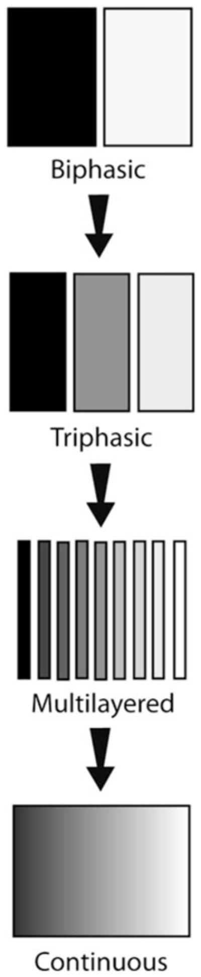
Scaffold morphology for interface tissue engineering has continued to use biphasic and triphasic solutions, although some have advanced toward multilayered approaches. Continuously-graded designs attempt to make higher resolution in physical and chemical properties.
GRADIENTS IN TISSUE ENGINEERING
Singh et al.56 and others15,35,48 have compiled comprehensive reviews on state-of-the-art applications for incorporating gradients in tissue engineering, illustrating numerous current and potential strategies for interfacial tissue engineering. Basic concepts for formulating multiple tissue systems42 rely on one or more forms of chemical or physical stimuli, which affect cell-specific movement, substrate affinity, or tissue formation.56 Furthermore, the majority of two-dimensional (2D) gradients utilizing these techniques have been intended for simply characterizing tissue engineering phenomena in the form of high-throughput screening, and have not necessarily been translated to 3D interfacial tissue applications. In addition, the resolution of native interfaces can take many forms, as primary interfaces (such as between soft tissue and bone, muscle, and tendon), or subsidiary interfaces (among articular cartilage layers, mineralized, and non-mineralized layers of fibrocartilage, tunicae of the vasculature, and dermal layering), which may imply a need for analogous resolution in the form of either stratified scaffolds or continuously graded approaches.
STRATIFIED INTERFACES
Recent stratified interfacial designs have focused on porosity or pore size,21,37,38,66 matrix proteins, 37,43,61,62,67 mineral,37,38,61,62,67 and bioactive factor 62 incorporation to resolve transitioning orthopedic tissue structures. There also exist stratifications of cell types2,14,33 or other features7,20,24,27,63,71 for vasculature network interface formation. Although it could be argued that a stratified approach does not yield a “true” continuous gradient, it can have many discrete advantages over continuous gradients. Because of the inherent discontinuous fabrication methods (developing sections separately and fusing together), however, design effort must be placed on ensuring that the interfacing layers are interconnected. Some emerging interfacial tissue engineering solutions currently exist only as methods, whereas others have been tested for their biological relevance in vitro or in vivo. The following sections review some recent design concepts and tissue regeneration on stratified constructs.
The Cortical–Cancellous Bone Interface
There exist many morphological and physiological characteristics of bone, such as osteon and Haversian canal localization to the cortical region, and marrow localization to the cancellous region. Tissue engineering solutions for this interface, however, rely largely on the differences in porosity and mineralization. For instance, a critical factor in designing constructs for bone tissue engineering is ensuring proper osseointegration within the host. A relevant method for accomplishing this comes from mineral incorporation within the scaffold itself. Ample evidence exists in the bone biology and tissue engineering literature for calcium-based minerals8,10,52 promoting osteoblastic behavior and the rate of in situ bone matrix formation, as variations of these minerals are already present in the native tissue. On a larger scale than seen in most tissue engineering applications, Hsu et al.21 demonstrated how to fabricate a composite scaffold mimicking the change in porosity among the cortical–cancellous bone interface, composed of only hydroxyapatite (HA), and tricalcium phosphate (TCP) (Table1). Polyurethane foams were either stitched or press-fitted together, then vacuum impregnated with HA and TCP, or dipped in ceramic slurry. Following drying, the polyurethane was removed by burnout. The resulting structure reflected a biphasic porosity, similar to the native tissue morphology, and four point bending tests suggested that the interface between the two layers was robust. However, the influence of this particular interface on in vitro and in vivo performance has yet to be demonstrated.
TABLE 1.
Notable applications of stratified scaffolds for orthopedic interface tissue engineering.
| Reference(s) | Stratification type(s) | Targeted interfacial tissues | Geometry and stratification direction | Material(s) used | Fabrication method(s) | Primary stratification value(s) |
|---|---|---|---|---|---|---|
| Hsu et al.21 | Porosity | Cortical–cancellous bone | 2 layer, cylindrical (radial layering), rectangular (axial layering) | TCP 118 and TCP 130 on PU foams with 20, 30, and 45 ppi ratings | Vacuum impregnation or dipping of ceramic mixture, both followed by PU burnout | Not directly evaluated |
| Vitale-Brovalone et al.66 | Porosity | Cortical–cancellous bone | 2 layer, cuboidal (axial layering) | SiO2–P2O5–CaO–MgO–Na2O–K2O (CEL2) bioglass. PE particles, and PU sponge | PE or PU burnout, glazing technique, sponge replication, and powder pressing | Porosity: 28–65% |
| Munoz-Pinto et al.46 | Material | Ligament–bone | Theoretical basis for stratification or graded properties in rectangular molds | PEG–DA and methacrylate-derived star PDMS | PDMS mixed with PEG and photopolymerized at 365 nm with 6 mW/cm2 for 2 min | Star PDMS:PEG weight ratios 0:100, 1:99, and 5:95 |
| Wang et al.68 and Spalazzi et al.59,60 | Porosity, material | Ligament (Phase A)–fibrocartilage (Phase B)–bone (Phase C) | 3 layer, cylindrical (axial layering) | Phase A: Polyglactin 10:90 knitted mesh, Phase B: PLGA 85:15 microspheres, Phase C:PLGA 85:15 and 45S5 Bioglass microspheres | Acquired mesh sheets, water–oil–water emulsion for microspheres, heat sintering for each layer | PLGA: 100% in Phase B to 75% in Phase C. Porosity: 58–27% across construct |
| Wahl et al.67 | Porosity, material | Cortical–cancellous bone, cartilage–bone | 2 layer, cylindrical (circumferential layering) and rectangular (axial layering) | Collagen I and 70% HA | SFF, freezing, critical point drying, DHT | Porosity: 87–95%, collagen: 1–5% |
| Liu et al.36,37 | Pore size, porosity, material | Cartilage (Region 1)–hypertrophic chondroctyes (Region-2)–bone (Region 3) | 3 layer, cylindrical (axial layering) | Region 1: PLGA 50:50, Region 2 and 3: PLGA 70:30 and TCP | Multinozzle lowtemperature deposition, particulate leaching | Region 1: 300–500 μm and 30–50 μm pores, 90% porosity; Region 2: <5 μm pores, 75% porosity; Region 3: 300–500 μm pores, 89% porosity |
| Ho et al.19 | Porosity, material | Cartilage–bone | 2 layer, cylindrical (axial layering) | PCL, TCP, and type I collagen | Fused deposition modeling of TCP powder in PCL for scaffold. Electrospinning of PCL/collagen | TCP: 0–25 w/w% TCP in PCL, porosity: 56–77% |
| Mimura et al.43 | Material | Cartilage–bone, cartilage–cartilage | 2 layer, cylindrical (radial and axial layering) | Outer sheath: 0.18% collagen I, Inner plug: 0.24% or 0.27% collagen I | Outer and inner layers: collagen suspension in buffers, then placed in mold | Increase in collagen concentration from outer to inner layers: 33% or 50% |
| Teng et al.62 | Pore size, material, eluted drug concentration | Any defect or interface | 3 layer, cylindrical (circumferential layering) | Chitosan, HA, and TCH (drug) | Mixing aqueous suspensions into molds with consecutive lyophilization cycles | Pore size: 40–250 μm, HA: 0–40 wt.%, TCP: 0–10% |
| Tampieri et al.61 | Porosity, material | Cartilage (Region 1)–tidemark (Region 2)–bone (Region 3) | 3 layer, cylindrical (axial layering) | Region 1: collagen I, Regions 2 and 3; HA/collagen | Region 1: precipitation of material, Regions 2 and 3: basic suspensions with HA, all regions: crosslinking with BDDGE | Pore size: 100–450 μm, collagen: 100–30%, HA: 0–70% |
| Kon et al.31 | Material, porositya | Cartilage–bone | 3 layer, cylindrical (axial layering) | Collagen type I and HA | Layers synthesized separately from porcine atelocollagen solution and non-stoichiometric HA deposition | Collagen (bone to cartilage): 30, 60, and 100%, HA (bone to cartilage): 70, 40, 0% |
| Reference(s) | Interface fusion and characteristics | Mechanical properties | Biological model(s) | Bulk tissue regeneration | Interface regeneration or cell interaction |
|---|---|---|---|---|---|
| Hsu et al.21 | Foams stitched or press-fitted together prior to mineral deposition and PU burnout | 4-point bending strength; homogenous HA/TCP foams: 18–20 MPa, layered product: 16 MPa | Not directly evaluated | Not directly evaluated | Not directly evaluated |
| Vitale-Brovalone et al.66 | Sintering of blocks with a thermal treatment (1000 °C for 3 h) | Unconfined compression tests; layered moduli: 2–18 MPa, solid CEL2: 33 Mpa | Not directly evaluated | Not directly evaluated | Not directly evaluated |
| Munoz-Pinto et al.46 | Not directly evaluated | PDM5:PEG from 0:100 to 5:95, mesh size: 1–3ζ; EM: 167–142 kPa | In vitro: rat calvarial osteoblasts encapsulated within gels for 28 days | Increasing PDMS concentration decreased CP, Col I, and OCN, and increased CS, Col II, and Sox9 expression | PDMS:PEG from 0: 100–5:95, fibronectin adsorption: 49–33 ng/cm2 |
| Wang et al.68 and Spalazzi et al.59,60 | Heat sintering of all phases together | In vivo, tri-cultured, compressive moduli at weeks 0–8: 100–83 MPa, yield strength at weeks 0–8: 10–4.5 MPa | In vitro: primary bovine osteoblasts and fibroblasts; in vivo: primary bovine chondrocytes, bovine neonatal osteoblasts and fibroblasts in athymic rat model | In vivo co-culture and triculture: mineral deposition heaviest in Phase C, lowest in Phase A | Only in triculture in vivo: neofibrocartilage with types I, II, and X collagen in Phase A and B (Figs. 2a and 2b) |
| Wahl et al.67 | Fusion in real time during manufacturing, well integrated | Higher collagen content yields higher modulus; 37–75 kPa. DHT can increase modulus overall | Not directly evaluated | Not directly evaluated | Not directly evaluated |
| Liu et al.36,37 | Fusion in real time during manufacturing, glutaraldehyde crosslinking | Not directly evaluated | In vivo: New Zealand White rabbits, constructs pre-cultured with rabbit BMSCs and implanted in patellar groove for 6 weeks | Bone-like tissue and cartilage-like tissues | Gradual transition, neo-tissues not isolated to specific regions |
| Ho et al.19 | Fusion in real time during laydown | Young’s modulus and yield strength of PCL: 15.7 and 2.12 MPa, of PCL–TCP: 124 and 4.2 MPa | In vivo: 6-month-old Yorkshire Duroc pigs with and without transplanted MSCs for 6 months | Mineralization and cartilage regeneration best in group with transplanted cells and PCL/collagen membrane | Interface incomplete at patellar groove and medial condyle in groups without cells and PCL/collagen membrane |
| Mimura et al.43 | Press-fit inner layer into outer sheath | Not directly evaluated | In vitro migration: MSCs from Japanese white rabbits; in vivo: patellar groove of Japanese white rabbits for 1, 2, 3, 4, 8, and 12 weeks | In vitro: migration significant for 33% collagen difference; in vivo: best cartilage regeneration with 33% collagen difference | Most mineralization at interface with 33% collagen difference, but not complete healing |
| Teng et al.62 | Successive fusion from dying interfaces intact | Not directly evaluated | Not directly evaluated | Not directly evaluated | Not directly evaluated |
| Tampieri et al.61 | Knitting procedure, lyophilization of stacked layers | For HA/collagen 70/30; porosity: 45–63%, flexural strength: 20–5 MPa, modulus: 7–2 MPa | In vitro: 2 week culture with chondrocytes; in vivo pre-culture with sheep BMSCs, ectopic implantation in nude mice for 8 weeks | In vitro: chondrocytes localized to collagen only layer, in vivo bone-like tissue and loose connective tissue | Well-defined interface biphasic appearance (Figs. 2c and 2d) |
| Kon et al.31 | Fusion via lyophilization | Not directly evaluated | In vivo: Homo sapiens, ten males, three females, age range: 27–51 years with clinical symptoms of knee pain/swelling with grade III–IV chondral or osteochondral lesions | Collagen type II and proteoglycan localized to cartilage region, Collagen type I in subchondral bone region | Reconstruction of a graded tissue transition in some regions, but scaffold not completely resorbed at 6 months, as indicated by MRI |
Implant was proprietary technology from Fin-Ceramica S.p.A., Faenza, Italy. Although no details on porosity were available, other studies demonstrate that such layering in HA/collagen ratio create different regional porosities. Hence, the porosity stratification was implied.
TCP, tricalcium phosphate; PU, polyurethane; ppi, pores per inch; PE, polyethylene; PEG-DA, poly(ethylene glycol) diacrylate; PDMS, poly(dimethyl siloxane); PLGA, poly(D,L–Latic-co-glycolic acid); HA, hydroxyapatite; SFF, solid freeform fabrication; DHT, dehydrothermal treatment; BMSC, bone marrow stromal cell; CP, calcium phosphate; Col I, collagen type I; OCN, osteocalcin; CS, chondroitin sulfate; Col II, collagen type II; Sox9, sex-determining region box 9; PCL, polycaprolactone; TCH, tetracycline hydrochloride; BDDGE, 4-butanediol diglycidyl ether; MSC, mesenchymal stem cell; MRI, magnetic resonance imaging.
Using bioactive glass composites for bone tissue engineering,1,23,64,65 specifically for mimicking the cortical–cancellous interface, is another method of interest, due to favorable biocompatibility and to moduli similar to native bone tissue. Vitale-Brovarone et al.66 used such a material to fabricate six different stratified porosity patterns (Table 1). Blocks of higher porosity were fabricated by burnout of polyethylene particles or polyurethane sponges from dried bioglass mixtures. Low porosity samples were made by layering and compressing the bioglass mixture. The resulting bi-porous composites were made by heat sintering sections together. These constructs were then subject to unconfined compression or cultured for a short period in simulated body fluid (SBF). The interfaces between porous regions were well integrated morphologically, and testing did not indicate that this area was a specific structural weakness. Incubation of the high porosity stratified constructs from sponge replication in SBF showed HA formation on the surface after only 7 days.
Just as with Hsu et al.’s approach,21 full in vitro characterization is needed to evaluate the effectiveness of this stratified technique for cortical–cancellous interface tissue engineering. With both techniques, an effective design to eliminate interface delamination was proposed, which is an important theme in stratified approaches to interfacial tissue engineering.
The Ligament/Tendon–Bone Interface
The bone-to-ligament interface (similar in many respects to the tendon–bone interface70) is comprised of mineralized (hypertrophic chondrocytes and collagen type X) and non-mineralized (ovoid chondrocytes and collagen types I and II) regions of fibrocartilage. Flanking this fibrocartilage interface are the ligament proper (fibroblasts) and subchondral bone (osteoblasts, osteoclasts, and osteocytes). This interface is unique, in that it is a more anatomically and physiologically distinguishable region than between cortical and cancellous bone, for instance. In fact, subsidiary interfaces exist within this interface, as between the non-mineralized and mineralized fibrocartilage. Furthermore, the bone-to-ligament transition can provide valuable information on how to approach all stratified orthopedic interfaces, addressing the issues of whether multiple tissue segments should be regarded as one large interface (or perhaps two, maybe three interfaces), and how one should formulate a scaffold design.
Munoz-Pinto et al.46 recently introduced a method for ligament-to-bone interface tissue engineering using hybrid hydrogels of poly(ethylene glycol) (PEG) and star poly(dimethylsiloxane) (PDMSstar) (Table 1). A stratified or graded construct was not explicitly fabricated, but the authors characterized the effects of PDMSstar-to-PEG weight ratio on osteoblast phenotype, gene expression, and biochemical production. With increasing inorganic (PDMSstar) content, there was a decrease in bone-like matrix and an increase in cartilage-like matrix.
Lu’s group39,40 has made considerable and detailed progress with addressing functional tissue regeneration of the bone-to-ligament interface. For example, a notable in vitro investigation by Wang et al.,68 using co-culture of fibroblasts and osteoblasts, emphasized the extensive influence that adjacent tissues have on forming the fibrocartilage interface (Table 1). Not only did overall cell proliferation decrease during co-culture, compared to culturing osteoblasts and fibroblasts separately, mineralization was also diminished in osteoblasts and enhanced in fibroblasts. Both cell types showed upregulation of genetic markers pertinent to the interfacial tissue, but a specific fibrocartilaginous interface was never formed. The absence of a fibrocartilaginous interface was also observed on a novel 3D triphasic construct during co-culture conducted by Spalazzi et al.,60 where an entire scaffold segment was dedicated to the interface. With all evidence indicating a missing aspect for formation of a fibrocartilage area, studies continued using co-culture and tri-culture of differing cell types (with chondrocytes for the interfacial region) in vivo (Table 1).45,59 Interestingly, tri-culture succeeded in forming a fibrocartilage region along with interface-relevant tissue matrix. However, this fibrocartilage was not fully localized to the intended middle phase of the scaffold (Figs. 2a and 2b). The authors acknowledged a limitation relating to scaffold production and chondrocyte seeding, and hinted at future methods for mitigating chondrocyte migration (and subsequent fibrocartilage formation) outside of the center of the construct. It could be concluded, perhaps, that more than one region of the construct was conducive to successful fibrocartilage formation.
FIGURE 2.

Scaffolds (a, c) and regenerated tissues (b, d) in interface tissue regeneration. (a) Triphasic scaffold for ligament–bone interface engineering, where Phase A was designated for the ligament proper, Phase B for the fibrocartilage interface, and Phase C for subchondral bone. (b) Fibrocartilage formed (arrow) in vivo during tri-culture with fibroblasts, chondrocytes, and osteoblasts, but was not localized strictly to Phase B. Scale bar = 500 μm in each panel. (c) Triphasic collagen/HA scaffold for osteochondral regeneration. Scale bar = 500 μm. (d) Bone-like and cartilage-like tissues regenerate successfully, but transition is not gradual. Scale bar = 1.0 mm. (a) Reprinted from J. Biomed. Res. A/86, Spalazzi, J., E. Dagher, S. Doty, X. Guo, S. Rodeo, and H. Lu, In vivo evaluation of a multiphased scaffold designed for orthopaedic interface tissue engineering and soft tissue-to-bone integration, 1–12, Copyright (2008), with permission from John Wiley and Sons; (b) Reprinted from Clin. Sports Med./28, Moffat, K., I. Wang, S. Rodeo, and H. Lu, Orthopedic interface tissue engineering for the biological fixation of soft tissue grafts, 157–176, Copyright (2009), with permission from Elsevier; (c, d) Reprinted from Biomaterials/29, Tampieri, A., M. Sandri, E. Landi, D. Pressato, S. Francioli, R. Quarto, and I. Martin, Design of graded biomimetic osteochondral composite scaffolds, 3539–3546, Copyright (2009), with permission from Elsevier.
In summary, efforts to regenerate the ligament–bone interface have included 2D and 3D studies to guide scaffold design. Important factors in the analysis of these designs have included the examination of how interfacing cell types react genetically, biochemically, and histologically to each other’s presence.
The Cartilage–Bone Interface
The cartilage-to-bone interface is comprised of several layers of collagen fibrils, with increasing chondrocyte density, and decreasing aggrecan content, approaching the articular surface. This articular surface is composed primarily of collagen type II, whereas the subchondral bone layer consists of osteoblasts, osteoclasts, and chondrocytes embedded in collagen type I and calcium-based minerals. Traditionally, cartilage-to-bone applications have used biphasic constructs to mimic the transition from chondrocytes in articular cartilage to osteoblasts in subchondral bone.22,26,41,49 Triphasic methods can introduce higher interfacial resolution, where a middle scaffold phase is incorporated to mimic the calcified cartilage transition region near the native osteochondral tidemark. Many applications even address subsidiary interfaces between individual cartilage layers.28 The following is an overview of the latest stratified osteochondral applications.
As noted, type I collagen incorporation for bone tissue engineering is gaining considerable attention, due to its ability to modulate cellular adhesion and phenotypes,11,18,44,47,53 aside from being the most abundant collagen in bone tissue. Wahl et al.67 presented a method for incorporating HA and type I collagen within shape-specific scaffolds via solid freeform fabrication (SFF). Using varying collagen concentrations, a stratification in pore size and porosity was achieved, where porosity was inversely proportional to Young’s modulus (Table 1), just as seen in Vitale-Brovarone et al.’s66 application.
Similarly, Liu et al.37 used multinozzle low-temperature deposition manufacturing (M-LDM) with collagen type I, chitosan, gelatin, TCP, and poly(D,L-lactic-co-glycolic acid) (PLGA) to create extremely complex interfacing surfaces for use with virtually any tissue engineering application (Table 1). Scanning electron microscopy (SEM) revealed that integration between natural and synthetic polymers was feasible, and the authors highlighted the ability to possibly interface materials with differing hydrophilicities, which could influence fluid dynamics, nutrient exchange, and biodegradation within any given construct. Recently, the same group conducted an in vivo study aiming to recreate the bone-to-cartilage transition with a triphasic composite.38 In addition to having triphasic porosity, there was also a stratification in materials (Table 1). After 6 weeks in a rabbit model, the scaffold performed favorably overall compared to a sham procedure, with a sharp transition between in situ tissues, instead of a stratification of mineralization.
Ho et al.19 utilized a biphasic construct with a change in porosity and TCP concentration, then implanted the scaffolds into porcine defects of the medial and patellar condyles (Table 1). Extensive characterization revealed that the presence of transplanted cells was beneficial compared to having just the scaffold.
Mimura et al.’s43 design used a radial change in collagen, with a higher collagen concentration in the scaffold center, to induce mesenchymal stem cell (MSC) migration to the center of full-thickness osteochondral defects as a possible treatment for injuries that are beyond the critical limit (Table 1). It was found that a step change of 33% collagen concentration was more effective at regeneration than a change of 50%, demonstrating that the benefits of stratification were not strictly proportional to the magnitude of change in chemical composition between layers.
Common materials for hard tissue engineering, such as chitosan and HA, can also be used in stratified designs for bioactive factor release. Teng et al.62 fabricated a radial change in material and porosity, which subsequently influenced the release of tetracycline hydrochloride from a core structure (Table 1). Having several layers of a porous construct could not only allow for cell penetration and tissue growth, but also for sequential delivery of growth factors to the site of regeneration.
In another triphasic design for osteochondral defects, layers of differing collagen type I and HA content were used to create a stratification of mineralization (Table 1).61 Although, in vitro, constructs were shown to favor chondrocyte matrix deposition only in the cartilage-like layer, tissue regeneration in vivo resembled two distinct tissue regions resembling bone and a cartilage-like tissue (Figs. 2c and 2d). Similarly, in a clinical study, Kon et al.31 used a triphasic scaffold, with a stratification of collagen I and HA, in 13 patients with osteochondral knee lesions (Table 1). Results of gross tissue regeneration and implant stability at 6 months were encouraging although the long-term clinical implications for this method, as other discussed orthopedic applications, are currently unknown.
In conclusion, stratifications of mineral content, collagen, and porosity are common approaches for osteochondral regeneration. In addition, it should be noted that SFF or M-LDM could be used to create not only layered designs (as seen here), but also continuous gradients, as it is a time-dependent and highly customizable process.
Vasculature Tissue and Network Interfaces
Tissue engineering of the vasculature with stratified scaffold designs is a relatively recent development. Anatomically, there exist three primary tissue layers in arteries and veins: the tunica externa (loose fibrous and connective tissue), the tunica media (smooth muscle), and the tunica intima (endothelial cells). Regeneration of such layers has great potential for traditional bypass techniques. In addition, these vessels are located throughout the body, creating a network for nutrient exchange. Thus, there are also interfaces between vessels and bulk tissue, where stratification is used to mainly recreate network hierarchies, as opposed to tunicae layers. Recent methods focus on regenerating both of these interface types.
For vascular layering, Thomas et al.63 used electrospinning to fabricate a tri-layered annular construct with a shallow radial change of porosity and mechanical properties, accomplished by transitioning between mass ratios of gelatin or elastin embedded in a bio-artificial polyglyconate (Table 2). Subsequent biodegradation studies demonstrated reduced mechanical integrity and inner layer delamination by 3 weeks, although the constructs still maintained a tensile strength near that of the native femoral artery.71
TABLE 2.
Recent applications of stratification in vascular interface tissue engineering.
| Reference(s) | Stratification | Targeted interfacial tissues | Geometry and stratification direction | Material(s) used | Fabrication method(s) | Primary stratification value(s) |
|---|---|---|---|---|---|---|
| Thomas et al.63 and Zhang et al.71 | Porosity, Material | Tunicae of the vasculature | 3 layer, cylindrical (radial layering) | Gelatin, elastin, polyglyconate | Electrospinning process | Molar ratio of trilayered GE/GEM/GM: 4:1/1:2:8/1:4, Porosity: 67–82% |
| Gauvin et al.14 (Fig. 3a) | Cell type | Tunicae of the vasculature | 2 layer, cylindrical (radial layering) | Smooth muscle cells, dermal fibroblasts | Cells grown on gelatin-coated tissue culture plate cell sheets rolled on tubular shaft in various configurations | Identical density of smooth muscle cells and fibroblasts |
| Kim et al.27 | Porosity | Tunicae of the vasculature | 2 layer, cylindrical (radial layering) | PLCL and sodium chloride | Gelatin PLCL spun onto tubular rod pretreated with NaCl, salt then leached out | Fibrous layer pore size ~153 μm and porosity ~67%, dual layer construct pore size average ~80 μm and porosity ~45% |
| Ju et al.24 | Fiber diameter, Pore area | Tunicae of the vasculature | 2 layer, cylindrical (radial layering) | Inner layer fibers: 5 w/v% PCL/collagen solution, Outer layer fibers: 15 w/v% PCL/collagen solution | Electrospinning process | Inner layer: FD ~0.3 μm, PA ~2 μm2, Outer layer: FD ~4.5 μm, PA ~1200 μm2 |
| Chen et al.7 | Drug loading, Eluted drug concentration | Bulk tissue and neovasculature | 2 layer (axial layering) | VEGF on mixture of PLGA 85:15 and 75:25 microspheres encapsulated with PDGF | PDGF microspheres from double emulsion, VEGF added ectopically by lyophilization in MVM alginate | Mathematical modeling for VEGF shows gradient of concentrations: 0–250 ng/mL, magnitude proportional to loading values of each protein |
| Asakawa et al.2 (Fig. 3b) | Cell type | Bulk tissue and neovasculature | 3 layer (axial layering) | Human umbilical vein endothelial cells and human dermal fibroblasts | Cell layers pressed together with plunger and 35 mm PIPAAm dish apparatus | Endothelial cells at 333,000 cells/layer, fibroblasts at 666,000 cells/layer |
| Lee et al.33 | Cell concentration | Skin layering, potential incorporation with vasculature | 10 layer, square or plus-shaped (axial layering) | Type I collagen, fibroblasts, keratinocytes | 3D freeform fabrication: bioprinter and automated dispensing nozzles | 106 cells per layer (or 93 cells per droplet)—acellular layers |
| Hoganson et al.20 (Fig. 3c) | Vasculature diameter, length, and incidence | Bulk tissue and neovasculature | 7 level, radial layering | Sylgard 184 poly(dimethylsiloxane) | PDMS cast into stainless steel made with soft lithography | Vessel diameters: 267–727 μm, pressures: 3–9 mmHg |
| Reference(s) | Interface and characteristics | Mechanical properties | Biological model(s) | Bulk tissue regenaration | Interface regeneration or cell interaction |
|---|---|---|---|---|---|
| Thomas et al.63 and Zhang et al.71 | Layered electrospinning and prolonged exposure to desiccant | Trilayered construct tensile strength: 3 MPa, tensile modulus: 20 MPa failure strain: 140%, native femoral artery TS: 3 MPa, TM: 9 MPa | Not directly evaluated | Not directly evaluated | Delamination of inner layer with degradation studies |
| Gauvin et al.14 (Fig. 3a) | Well-integrated tissue matrix | UTS ~2 MPa, BP ~1000 mmHg, LM ~13 MPa, and FS ~35% for single step method | Cultured layered constructs in vitro for 14 days after 28-day cell sheet formation and construct rolling | Type I collagen present in all layers, while elastin present only with certain rolling methods utilizing fibroblasts | Layer integration and thickness dependent upon cell type and assembly method |
| Kim et al.27 | SEM reveals integration between inner compact layer and gel fibers | UTS ~3 MPa, BP ~900 mmHg, LM ~0.82 MPa, and FS ~604% | Blood infusion to evaluate leakage and burst pressure | Not directly evaluated | Not directly evaluated |
| Ju et al.24 | SEM shows integrated but distinct layers | Inner layer: UTS ~3 MPa, LM ~2 MPa, FE ~90%; Outer layer: UTS ~0.75 MPa LM ~0.26 MPa, FE ~734% | Smooth muscle cells and endothelial cells cultured in vitro | Endothelial cell adhesion localized to lumen, while SMCs infiltrated outer layer. Both cell types maintained native phenotypes | Layers and cell types segregated, interface had lowest cell density |
| Chen et al.7 | Layers pressed together at 1500 psi | Not directly evaluated | Mathematical modeling and in vivo: mouse hindlimb ischemia for 2 and 6 weeks | No major limitations of bulk connective tissue regeneration | Neovasculature interface with bulk tissue more mature, less dense, with sequential delivery of VEGF and PDGF from different layers |
| Asakawa et al.2 (Fig. 3b) | Layer fused with fibrin gel at 37 °C | Not directly evaluated | Multilayered sheets cultured for 3 or 7 days in vitro | Lumen area greatest in constructs with two fibroblast layers on top of a single endothelial cell layer, as opposed to single endothelial layer between two fibroblast layers | Multiple, distinct tubular formation via immunofluorescence confocal laser micrograph |
| Lee et al.33 | Layers crosslinked by nebulized aqueous sodium bicarbonate | Not directly evaluated | In vitro: primary adult human dermal fibroblasts and epidermal keratinocytes, cultured for 8 days at most | No statistical difference in tissue properties between printed cells and control | Cell types localized to intended layers |
| Hoganson et al.20 (Fig. 3c) | Not directly evaluated | Shear stress variation between 11 and 23 dyne/cm3. Other properties not evaluated | Mathematical modeling and in vitro loading with anticoagulated sheep blood | Not directly evaluated | Not directly evaluated |
PLCL, poly(L-lactide-co-e-caprolactone); PCL, polycaprolactone; VEGF, vascular endothelial growth factor; PLGA, poly(D,L-latide-co-glycolic acid); PDGF, platelet-derived growth factor; NaCl, sodium chloride; MVM, alginate gels with >50% mannuronic units; PIPPAm, poly(N-isopropylacrylimide); PDMS, poly(dimethylsiloxane), GE, gelatin-elastin; GEM, gelatin-elastin-maxon; GM, gelatin-maxon; FD, Fiber diameter; PA, pore area; SEM, scanning electron microscopy; TS, tensile strain; TM, tensile modulus; UTS ultimate tensile strength; BP, burst pressure; LM, longitudinal modulus; FS, failure strain; FE, fracture elongation; SMC, smooth muscle cell.
Gauvin et al.14 developed a cell-only single-step method for recreating small-caliber arterial grafts (a tunica media and intima) with layers of dermal fibroblasts and smooth muscle cells (SMC) (Table 2). The two cell types were cultured adjacently to each other and allowed to integrate for 28 days, and were then rolled onto a tubular support; SMC first, then fibroblasts (Fig. 3a). After the constructs were cultured for 14 days, mechanical testing demonstrated enhanced ultimate tensile strength, burst pressure, and linear modulus compared to rolling the two layers separately.
FIGURE 3.

Recent methods for creating stratifications in vasculature interfaces and networks. (a) Single-step method for creating layered vascular tunicae from SMC and fibroblasts cultured adjacently (ssTEVMA: single-step tissue-engineered media and adventitia); (b) placement of endothelial cells (EC) below fibroblasts (Fb) promotes lumen formation (green) inside fibroblastic bulk tissue (red) as early as 7 days; (c) computer-generated stratifications of vascular patterns can be used with soft lithography to generate 2D, or eventually 3D, organ-level networks, which deliver continuous pressure gradients and a narrow range of shear stress. (a) Reprinted from Tissue Eng. A, Gauvin, R., T. Ahsan, D. Larouche, P. Lévesque, J. Dubé, F. A. Auger, R. M. Nerem, and L. Germain, A novel single-step self-assembly approach for the fabrication of tissue-engineered vascular constructs, Online ahead of print, Copyright (2010), with permission from Mary Ann Liebert; (b) Reprinted from Biomaterials/31, Asakawa, N., T. Shimizu, Y. Tsuda, S. Sekiya, T. Sasagawa, M. Yamato, F. Fukai, and T.Okano, Pre-vascularization of in vitro three-dimensional tissues created by cell sheet engineering, 3903–3909, Copyright (2010), with permission from Elsevier; (c) Reprinted from Tissue Eng. A, Hoganson, D. M., H. I. Pryor, I. D. Spool, O. H. Burns, J. R. Gilmore, and J. P. Vacanti, Principles of biomimetic vascular network design applied to a tissue-engineered liver scaffold, Online ahead of print, Copyright (2010) with permission from Mary Ann Liebert.
Kim et al.27 utilized a poly(L-lactide-co-ε-caprolactone) (PLCL) solution spun onto a tubular shaft in a non-solvent to create a bi-layered pore stratification (Table 2). The shaft was pre-treated with sodium chloride (NaCl), which became incorporated with the inner layer of the PLCL fibers during deposition. The salt was leached out following fabrication, creating smaller pores on the inner layer, whereas fiber collection on the outside formed larger pores. Mechanical testing revealed circumferential and longitudinal tensile strengths that were superior to those of the canine abdominal aorta.
Ju et al.24 created a 3D bi-layered scaffold with poly(caprolactone) (PCL) and collagen via electrospinning (Table 2). A change in fiber diameter, and subsequent change in pore volume, was created by layering different concentrations of PCL and collagen in a solvent. Mechanical testing showed that smaller fiber diameters had higher ultimate tensile strengths, elastic moduli, and percent elongations at failure. In addition, the construct was able to localize endothelial and SMC to the different layers.
Other techniques focused on creating neo-synthesized tissue networks, and stratified designs in bioactive factors can be used to address the intricacies of forming such interfaces within a bulk tissue. The relevance of this hierarchy in patterning blood vessel formation was fully appreciated by Chen et al.7 (Table 2), in atypical applications of stratified scaffolds that they recognized earlier.51 Their investigation was particularly unique for two reasons. Firstly, a stratified scaffold design was used to introduce a spatial element to temporal formation, and maturation, of neo-synthesized blood vessels. Secondly, while growth factor loading was biphasic in nature, a continuous gradient in concentration existed when the proteins were eluted.
Another recent method for pre-vascularization of tissues was introduced by Asakawa et al.2 by layering of only fibroblasts and endothelial cells in alternating patterns (Table 2). A fibrin gel was used to fuse cell layers with a plunger and dish apparatus. The method demonstrated that the cell types remained within their intended stratified regions, and endothelial cell placement controlled the size and location of lumen formation within the construct (Fig. 3b).
Similar methods in epidermis printing have the potential to be used in vasculature networks as well, as these are contiguous tissue components in the body. Recently, Lee et al.33 created a ten-layer construct for epidermis grafting. Even though some layers were identical in composition, the technique enabled the isolation of fibroblasts or keratinocytes to 300 μm slices, with the whole construct being less than 3.0 mm in thickness (Table 2). Fluorescent labeling confirmed cell localization to the intended layers. In this case, having a continuous gradient along the depth of the construct would not allow for isolated cell printing, where perhaps many layers of different cell types, or discretely controlled cell densities, would be possible. Although not directly applied to graded interface tissue engineering, recent applications using two-photon laser scanning photolithographic techniques in bioactive hydrogels could be similarly applied for 3D migration and localization of cell populations.34
Finally, stratifications in microvascular density can be used to address organ-wide regenerative therapies. A notable and recent computer-aided design created radial changes in vascular diameter, length, and density to mimic the venous architecture of a liver lobule (Table 2).20 Sheep’s blood was pumped through molded PDMS in vitro to simulate native blood flow. Interestingly, the stratification of physical dimensions created a continuous pressure gradient across the assembly, all while minimizing the variation of shear stress at the wall (Fig. 3c). This method could also have large-scale potential, as multi-layering of such radial networks could create 3D stratifications.
Furthermore, a stratified approach for vascular interfaces may prove to be superior to a continuously graded one, as localization of specific cell types and tissue morphologies to different regions of regenerated vessels is crucial to prevent blood leakage, maintain mechanical integrity, and to create high resolution in these networks with cellular layering.
Summary of Stratified Designs
In summary, stratified 3D scaffold designs for interfacial tissue regeneration are being used diversely, with most applications generating improvements in mechanical properties and/or tissue integration. There exist simple fabrication methods that mimic a structure–function relationship for the cortical–cancellous interface, or add even more complexity to this structure–function with time-dependent or protein- and mineral-based processes for cartilage–bone and ligament–bone interfaces. In addition, novel applications capitalizing on the aspect of having compartmentalized regions, such as in de novo vascular formation, endothelial cell layering, epidermal printing, and vascular network hierarchies, may be comparable or superior to continuous gradient approaches. Another distinct advantage of stratified designs is for bioactive factor encapsulation, where layering can provide a delayed release or multiple specific sequential release rates. The key issue, however, is how much influence the physical or chemical characteristics of the whole construct have on the regeneration of the interfacial region. Studies reviewed here, along with reviews of other stratification methods,26,28,41,49,70 have made it possible for tissue engineers to begin to critically assess the performance of stratified interface designs for specific applications, compared to continuously graded approaches. Specifically, as observed in some in vivo orthopedic applications highlighted earlier,38,59,61 the morphology or occurrence of neo-tissue formation is not necessarily dependent upon stratified scaffold design intricacies. This does not imply that material selection or characteristics are irrelevant, but perhaps specific physical, chemical, or topological properties can be utilized continuously in such a way that is conducive to multiple tissue formation in one seamless construct. Such concepts are gaining attention in the tissue engineering community, and with a burgeoning number of continuously graded 3D designs for interfacial strategies.
CONTINUOUS INTERFACES
Here, a diverse sampling of methods for creating continuous 3D gradients for interfacial tissue engineering is presented. Recent methods employed gradients in transcription factors,50 nanoparticle incorporation,13 porosity,5 bioactive factor release,58,69 and HA precipitation.36 There exists a myriad of continuously graded 2D and 3D studies56 that have been used in modifying surface chemistry or quantifying cellular guidance, applied to implant design, or simply inferred for potential use in tissue engineering applications.
Fabrication methods for creating changes in porosity and pore size need not be a multiple step process. For example, Bretcanu et al.5 utilized a bioactive glass and heat treatment, along with an aluminum mold, to fabricate a continuous gradient in porosity (Table 3). With this method, a gradient could theoretically be created in any direction, at any length, creating narrow or broad pore size ranges. Once the pore gradient is made, a construct of any shape could be extracted. This type of fabrication might be most useful in filling longitudinal-, wedge-, or cubicalshaped defects that penetrate a small volume of cortical and cancellous bone. Full circumferential recreations of the cortical–cancellous interface, as seen previously with stratified techniques,21,66 may be more difficult to recreate. Additionally, the in vitro and in vivo potential has yet to be evaluated.
TABLE 3.
Recent applications of continuous gradients for orthopedic interfacial tissue engineering.
| Reference(s) | Gradient type(s) | Targeted interfacial tissues | Geometry and gradient direction | Material(s) used | Fabrication method(s) |
|---|---|---|---|---|---|
| Bretcanu et al.5 | Porosity | Cortical–cancellous bone | Any shape (axial direction) | PU sponges and 45S5 Bioglass slurry | Dipping in bioglass and burnout of PU |
| Liu et al.36 | Porosity, Material | Cartilage–bone or any mineralized tissues | Cylindrical (axial gradient) | Collagen l and nonstoichiometric nano HA | Modified diffusion model of calcium and phosphate across scaffold at pH = 8.5, cross-linking treatment |
| Erisken et al.13 | Material | Soft tissue–bone | Cylindrical (axial gradient) | ε-polycaprolactone and β-TCP | Twin-screw extrusion/electrospinning process, time-dependent feed of TCP |
| Singh et al.56–58 and Dormer et al.12 | Drug loading, Material | Cartilage–bone | Cylindrical (axial gradient) | PLGA 50:50, CaCO3, TiO2 BMP-2, TGF-β1 | Precision particle fabrication for PLGA microspheres, programmable pumps for gradient |
| Wang et al.69 | Drug loading | Cartilage–bone | Cylindrical (axial gradient) | PLGA 50:50, silk fibroin, alginate, BMP-2 and IGF-1 for release, HRP for microsphere gradient magnitude | PLGA microspheres from water-in-oil-in-water dispersion, silk microspheres from lipid film/freeze-thaw/centrifugation process, gradient from controlled pump rate |
| Phillips et al.50 (Fig. 4) | Transcription factor | Soft tissue–bone | 3D slice (longitudinal gradient) | Collagen, poly (L-lysine), Runx2/Cbfa1 | Time-dependent dipping process of collagen scaffold in PLL with bound Runx2/Cbfa1 |
| Reference(s) | Primary gradient value(s) | Mechanical properties | Biological model(s) | Bulk tissue regeneration | Interface regeneration or cell interaction |
|---|---|---|---|---|---|
| Bretcanu et al.5 | Not directly measured after complete process, gradient magnitude proportional to degree of compression | Not directly evaluated | None | None | None |
| Liu et al.36 | Calcium: 3–19%, overall porosity: 45%, gradient in porosity inferred from regional HA crystal morphology | Not directly evaluated | In vitro: resistance to biodegradation, in vivo: 50% of construct remaining at 4 weeks | None | None |
| Erisken et al.13 | Tricalcium phosphate: 0–15 wt.% | Failure properties corresponding with 0–12 wt.% TCP, stress: 880–1100 kPa, elongation: 250–175% | In vitro: mouse preosteoblasts (MC3T3E1) for 4 weeks | Calcium deposition and collagen synthesis, culture significantly increased compressive modulus and toughness by 4 weeks | Graded appearance in calcium deposition and cell nuclei |
| Singh et al.56–58 and Dormer et al.12 | BMP-2 & TGF-β1: 0–100%(opposing gradients), stiffness factors: 0–100% | Up to 400 kPa at onset of culture, ~3 kPa after 6 weeks in vitro | In vitro: hUCMSCs and hBMSCs for 6 weeks | Increased biochemical output from graded scaffolds, upregulation of some bone and cartilage markers on single graded construct | Regionalized bone-like and cartilage-like matrix |
| Wang et al.69 | Factor increase in (1) PLGA microsphere number across scaffold: 2–2.5×, (2) BMP-2 across length 15×, (3) IGF-1 across length: 4.5× as examples | Not directly evaluated | In vitro: MSCs | Homogenous cell distribution, graded increase in biochemical production and gene transcription | Heterogeneous proteoglycan and calcium deposition |
| Phillips et al.50 (Fig. 4) | Post fabrication PLL gradient via FITC intensity: decrease of 2.72 R.F.I/μm scaffold length, after in vivo implantation mineral volume (mm3): decrease from 0.8 to 0.0 in first 8 mm of 14 mm scaffold | Max force at failure, stiffness, Young’s modulus, and maximum stress all at least 2× higher on mineralized (Runx2/Cbfa 1-osteogenic) side than fibroblast side | In vitro: Wistar rat fibroblasts, in vivo: ectopic implanation in syngeneic rats after 24 h preculture, harvest at 2 weeks | In vitro: homogenous cell distribution, Runx2-expressing cells graded in number across construct | In vitro: graded mineral deposition, in vivo: deep gradient in mineral deposition localized to one side of the construct |
PU, polyurethane; HA, hydroxyapatite; TCP, tricalcium phosphate; PLGA, poly(D,L-lactic-co-glycolic acid); CaCO3, calcium carbonate; TiO2, titanium oxide; BMP, bone morphogenetic protein; IGF, insulin-like growth factor; HRP, horseradish peroxidase; Runx2, runt-related transcription factor-2; Cbfa1, core binding factor-α-1; PLL, poly(L-lysine); FITC, fluorescein isothiocyanate; RFI, relative FITC intensity; hUCMSC, human umbilical cord matrix stromal cells; hBMSC, human bone marrow stromal cells.
The incorporation of calcium-based additives along with proteins or polysaccharides is a recurring theme for osteochondral applications, as seen in this review alone.37,38,61,62,67 Recently, Liu et al.36 proposed a method for creating a collagen scaffold with a gradient of HA (Table 3). Fabrication was based upon a modified diffusion method, where phosphate and calcium ions migrated down their respective concentration gradients, across the base construct. Depending on the concentration of calcium in any given region, different morphologies of HA crystals were formed, and the overall porosity was controlled by collagen content.
Electrospinning is another time-dependent process that makes fabrication of continuously graded scaffolds possible. Erisken et al.13 used a twin-screw extrusion process with PCL to create a continuous gradient of TCP nanoparticles (Table 3). The presence of a TCP gradient was evident through SEM and Von Kossa staining. Due to incorporation of a stiff nanomaterial, the scaffolds were also functionally graded, which was verified by mechanical testing. In addition, the compressive modulus and toughness of the graded constructs increased considerably after culture with pre-osteoblasts.
Singh et al.58 presented the first report of a technique for formulating a continuous 3D gradient in bioactive factors using microspheres.58 Using programmable pumps and a precision particle fabrication process that created monodisperse microparticles, an axial gradient in volumetric composition was made (Table 3). Although the initial characterization included only microspheres loaded with rhodamine dye to demonstrate the gradient profile, essentially any bioactive factor could be encapsulated in either side [e.g., bone morphogenetic protein (BMP)-2 and transforming growth factor (TGF)-β1 for a bone–cartilage interface], formulating opposing gradients for interface generation. Recently, the same technology was used to encapsulate titanium dioxide (TiO2) and calcium carbonate (CaCO3), formulating a gradient in stiffness.57 Combining a stiffness and growth factor gradient could also be achieved with this process, along with many types of microsphere formulations (double-walled, 30,72 porous,3,25 or with HA55). Recently, Dormer et al.12 completed an in vitro characterization of the microsphere-based gradient design, where opposing growth factor gradients of TGF-β1 and BMP-2 produced regionalized extracellular matrix and outperformed the blank control scaffolds in biochemical production and gene expression of some major osteogenic and chondrogenic markers (Table 3).
Recently, Wang et al.69 presented a gradient microsphere method, but suspended PLGA or silk microspheres inside silk or alginate gels with MSCs. Using BMP-2 and insulin-like growth factor (IGF)-1, single or opposing gradients were made to regenerate the soft tissue-to-bone transition (Table 3). Most notably, the study found that opposing (dual) gradients in bioactive signaling increased GAG and calcium content, along with collagen I and II gene expressions, compared to groups having only a single growth factor gradient. With this method, a bioactive gradient may be better maintained over time, as the gel environment may mitigate rapid growth factor diffusion out of their respective regions of the construct.
Lastly, Phillips et al.50 presented a method for localizing continuous gradients onto interfacial constructs, and not relying on growth factor elution to induce cell differentiation (Table 3). Using a time-dependent dipping procedure with a motorized dip coater, a gradient of retrovirus encoding runt-related transcription factor 2 (Runx2) was deposited on top of a gradient of poly(L-lysine). The gradient was oriented along the length of the collagen scaffold. When seeded with fibroblasts, the construct was successful in creating a gradient of osteoblastic differentiation (osteoblasts and fibroblasts on one construct). When the scaffolds were evaluated in vitro and in vivo for mineral deposition, the in vivo mineral distribution appeared to be more biphasic in nature after just 2 weeks, whereas the in vitro constructs maintained a more continuous mineral gradient for 42 days (Fig. 4). The in vivo behavior is reminiscent of an application for ligament–bone interface engineering59 and other cartilage–bone applications,38,61 where tissue generation patterns did not necessarily adhere to the initial scaffold design. In addition, Phillips et al.’s50 technique induced a functional gradient from a strictly biochemical surface gradient.
FIGURE 4.
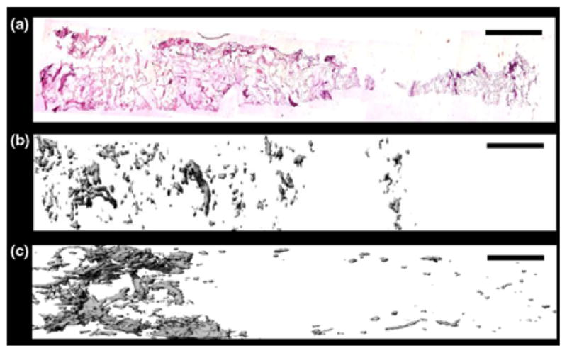
Continuously graded constructs for soft tissue—bone. (a) Immunohistochemical staining for eGFP (pink) counterstained with hematoxylin (blue) revealed a gradient of Runx2—expressing cells. (b) Mineral deposition via μCT after 42 days of in vitro culture. (c) Mineral deposition via μCT after 2 weeks of ectopic in vivo implantation. The gradient became steeper and more localized after in vivo culture. Scale bar = 2 mm. (a–c) Reprinted from Proc. Natl. Acad. Sci./105 Phillips, J. E., K. L. Burns, J. M. Le Doux, R. E. Guldberg, and A. J. García. Engineering graded tissue interfaces, 12170–12175, Copyright (2008) National Academy of Sciences, U.S.A.
Summary of Continuous Gradients
In summary, techniques to create continuous 3D gradients for orthopedic interface tissue engineering generally involve a time-dependent process, as do the more complex stratified designs. Incorporation of bioactive factors can have varying levels of control over the effective region, either by release directly into the cell culture medium, into a gel network, or being completely immobilized on a substrate. In vitro, continuous gradients thus far have demonstrated continuous gradients of tissue-specific matrix as intended; however, in vivo, a continuous design may abandon its original continuous gradation, as it becomes subject to cascades of native biological processes that define location and morphology of the interface. Specifically, a gradient approach could provide more regenerative control to nature, using a continuous transition of signals, directing the interface to form in a specified region, which, ultimately, may be conducive to custom-made, patient-specific regenerative designs. Methods for creating such smooth, seamless transitions between tissue regions are not necessarily more elaborate, or time-consuming, than their stratified counterparts.
CONCLUSION
As tissue engineering and regenerative medicine moves forward, the search continues for missing ingredients in regenerating ideal tissue interfaces, a process that must take tissue functionality into consideration (Fig. 5). What are these missing elements for interfacial tissue engineering? In some instances, as seen in this review, the missing elements could be one or several things (e.g., simply taking the design from 2D to 3D or from in vitro to in vivo environments, adding an extra cell type or bioactive substrate, a slower release profile for a growth factor, or a combination of these). After several iterations of this process, researchers will be able to determine a minimum formulation of concerted regenerative signals, such as (1) critical physical morphologies like pore size or porosity, (2) specific concentrations, locations, or temporal release profiles of bioactive signals, (3) essential bulk material properties such as mineral density or protein content, and (4) all of the aforementioned characteristics presented in a stratified manner or continuously graded fashion for multiple tissue regeneration (Fig. 5).
FIGURE 5.

Iterative design process for developing functional interfacial tissue solutions. Moving from 2D to in vivo environments requires constant characterization of each element (cells, signals, and scaffolds), to find the simplest solution available for indications that interface-relevant tissue is forming. Once reaching the in vivo stage, it will be important to formulate scaffolds that are successful in tissue regeneration without cell transplantation, which will require engineers to recollect the most critical design aspects thus far. One can begin the design process anywhere in this schematic, but skipping 2D and 3D in vitro characterizations may hinder the discovery of design parameters that are critical for success, or allow for designs to carry superfluous factors to the final stage. Using continuously graded scaffolds grants extra regenerative control to nature at this final stage.
While stratified and continuous scaffold designs have primarily been employed in orthopedics, new applications of these interfacial gradient designs (e.g., vascular regeneration) are rapidly growing. Stratified and continuous scaffold designs each have their advantages. For example, stratified techniques can have specialized applications for localization of endothelial or epithelial cell populations, creating discrete sequences of drug release, or large-scale vascular network patterning. In addition, depending on available equipment, the technology to create continuous gradients may not be available. However, there are numerous instances where equipment being used for fabricating stratified scaffolds could easily be adjusted to create continuous gradients (e.g., various SFF methods). In contrast, continuous gradient designs represent a seamless interfacial transition that better approximates the gradual, rather than sharp, interface between native tissues. Only time will tell whether continuous or stratified scaffold designs will provide better results in vivo, or whether one may be more well suited than the other depending on the specific application. Nevertheless, continuously graded designs may represent the next generation of interfacial tissue engineering solutions.
Acknowledgments
The authors would like to acknowledge funding from the Arthritis Foundation, the National Institutes of Health (NIH/NIDCR 1 R21 DE017673-01), and the Oral and Maxillofacial Surgery Foundation. The authors would also like to acknowledge the NIGMS/NIH Pharmaceutical Aspects of Biotechnology Training Grant (T32-GM008359) for supporting N. H. Dormer.
References
- 1.Alcaide M, Portolés P, López-Noriega A, Arcos D, Vallet-Regí M, Portolés MT. Interaction of an ordered mesoporous bioactive glass with osteoblasts, fibroblasts and lymphocytes, demonstrating its biocompatibility as a potential bone graft material. Acta Biomater. 2010;6(3):892–899. doi: 10.1016/j.actbio.2009.09.008. [DOI] [PubMed] [Google Scholar]
- 2.Asakawa N, Shimizu T, Tsuda Y, Sekiya S, Sasagawa T, Yamato M, Fukai F, Okano T. Pre-vascularization of in vitro three-dimensional tissues created by cell sheet engineering. Biomaterials. 2010;31:3903–3909. doi: 10.1016/j.biomaterials.2010.01.105. [DOI] [PubMed] [Google Scholar]
- 3.Bae S, Son J, Park K, Han D. Fabrication of covered porous PLGA microspheres using hydrogen peroxide for controlled drug delivery and regenerative medicine. J Controlled Release. 2009;133:37–43. doi: 10.1016/j.jconrel.2008.09.006. [DOI] [PubMed] [Google Scholar]
- 4.Bian W, Bursac N. Tissue engineering of functional skeletal muscle: challenges and recent advances. IEEE Eng Med Biol Mag. 2008;27:109–113. doi: 10.1109/MEMB.2008.928460. [DOI] [PMC free article] [PubMed] [Google Scholar]
- 5.Bretcanu O, Samaille C, Boccaccini A. Simple methods to fabricate Bioglass®-derived glass–ceramic scaffolds exhibiting porosity gradient. J Mater Sci. 2008;43:4127–4134. [Google Scholar]
- 6.Chan G, Mooney D. New materials for tissue engineering: towards greater control over the biological response. Trends Biotechnol. 2008;26:382–392. doi: 10.1016/j.tibtech.2008.03.011. [DOI] [PubMed] [Google Scholar]
- 7.Chen R, Silva E, Yuen W, Mooney D. Spatio–temporal VEGF and PDGF delivery patterns blood vessel formation and maturation. Pharm Res. 2007;24:258–264. doi: 10.1007/s11095-006-9173-4. [DOI] [PubMed] [Google Scholar]
- 8.Cheng L, Ye F, Yang R, Lu X, Shi Y, Li L, Fan H, Bu H. Osteoinduction of hydroxyapatite/β-tricalcium phosphate bioceramics in mice with a fractured fibula. Acta Biomater. 2010;6(4):1569–1574. doi: 10.1016/j.actbio.2009.10.050. [DOI] [PubMed] [Google Scholar]
- 9.Chung C, Burdick J. Engineering cartilage tissue. Adv Drug Deliv Rev. 2007;60:243–262. doi: 10.1016/j.addr.2007.08.027. [DOI] [PMC free article] [PubMed] [Google Scholar]
- 10.Daugaard H, Elmengaard B, Bechtold JE, Jensen T, Soballe K. The effect on bone growth enhancement of implant coatings with hydroxyapatite and collagen deposited electrochemically and by plasma spray. J Biomed Mater Res A. 2009 doi: 10.1002/jbm.a.32303. (published online ahead of print) [DOI] [PMC free article] [PubMed] [Google Scholar]
- 11.De Assis AF, Beloti MM, Crippa GE, De Oliveira PT, Morra M, Rosa AL. Development of the osteoblastic phenotype in human alveolar bone-derived cells grown on a collagen type I-coated titanium surface. Clin Oral Implants Res. 2009;20:240–246. doi: 10.1111/j.1600-0501.2008.01641.x. [DOI] [PubMed] [Google Scholar]
- 12.Dormer N, Singh M, Wang L, Berkland C, Detamore M. Osteochondral interface tissue engineering using macroscopic gradients of bioactive signals. Ann Biomed Eng - Special Issue on Interfacial Bioeng. 2010 doi: 10.1007/s10439-010-0028-0. [DOI] [PMC free article] [PubMed] [Google Scholar]
- 13.Erisken C, Kalyon D, Wang H. Functionally graded electrospun polycaprolactone and β-tricalcium phosphate nanocomposites for tissue engineering applications. Biomaterials. 2008;29:4065–4073. doi: 10.1016/j.biomaterials.2008.06.022. [DOI] [PubMed] [Google Scholar]
- 14.Gauvin R, Ahsan T, Larouche D, Lévesque P, Dubé J, Auger FA, Nerem RM, Germain L. A novel single-step self-assembly approach for the fabrication of tissue-engineered vascular constructs. Tissue Eng A. 2010 doi: 10.1089/ten.TEA.2009.0313. (online ahead of print) [DOI] [PubMed] [Google Scholar]
- 15.Genzer J, Bhat R. Surface-bound soft matter gradients. Langmuir. 2008;24:2294–2317. doi: 10.1021/la7033164. [DOI] [PubMed] [Google Scholar]
- 16.Grayson W, Chao P, Marolt D, Kaplan D, Vunjak-Novakovic G. Engineering custom-designed osteochondral tissue grafts. Trends Biotechnol. 2008;26:181–189. doi: 10.1016/j.tibtech.2007.12.009. [DOI] [PMC free article] [PubMed] [Google Scholar]
- 17.Grayson W, Martens T, Eng G, Radisic M, Vunjak-Novakovic G. Biomimetic approach to tissue engineering. Semin Cell Dev Biol. 2009;20:665–673. doi: 10.1016/j.semcdb.2008.12.008. [DOI] [PMC free article] [PubMed] [Google Scholar]
- 18.Hennessy KM, Pollot BE, Clem WC, Phipps MC, Sawyer AA, Culpepper BK, Bellis SL. The effect of collagen I mimetic peptides on mesenchymal stem cell adhesion and differentiation, and on bone formation at hydroxyapatite surfaces. Biomaterials. 2009;30:1898–1909. doi: 10.1016/j.biomaterials.2008.12.053. [DOI] [PMC free article] [PubMed] [Google Scholar]
- 19.Ho STB, Hutmacher DW, Ekaputra AK, Hitendra D, James HHP. The evaluation of a biphasic osteochondral implant coupled with an electrospun membrane in a large animal model. Tissue Eng A. 2009 doi: 10.1089/ten.TEA.2009.0471. (online ahead of print) [DOI] [PubMed] [Google Scholar]
- 20.Hoganson DM, Pryor HI, Spool ID, Burns OH, Gilmore JR, Vacanti JP. Principles of biomimetic vascular network design applied to a tissue-engineered liver scaffold. Tissue Eng A. 2010 doi: 10.1089/ten.tea.2009.0118. (online ahead of print) [DOI] [PMC free article] [PubMed] [Google Scholar]
- 21.Hsu Y, Turner I, Miles A. Fabrication of porous bioceramics with porosity gradients similar to the bimodal structure of cortical and cancellous bone. J Mater Sci: Mater Med. 2007;18:2251–2256. doi: 10.1007/s10856-007-3126-2. [DOI] [PubMed] [Google Scholar]
- 22.Hutmacher D. Scaffolds in tissue engineering bone and cartilage. Biomaterials. 2000;21:2529–2543. doi: 10.1016/s0142-9612(00)00121-6. [DOI] [PubMed] [Google Scholar]
- 23.Jo JH, Lee EJ, Shin DS, Kim HE, Kim HW, Koh YH, Jang JH. In vitro/in vivo biocompatibility and mechanical properties of bioactive glass nanofiber and poly(epsilon-caprolactone) composite materials. J Biomed Mater Res B. 2009;91:213–220. doi: 10.1002/jbm.b.31392. [DOI] [PubMed] [Google Scholar]
- 24.Ju YM, Choi JS, Atala A, Yoo JJ, Lee SJ. Bilayered scaffold for engineering cellularized blood vessels. Biomaterials. 2010;31:4313–4321. doi: 10.1016/j.biomaterials.2010.02.002. [DOI] [PubMed] [Google Scholar]
- 25.Kang S, La W, Kim B. Open macroporous poly (lactic-co-glycolic acid) microspheres as an injectable scaffold for cartilage tissue engineering. J Biomater Sci Polym Ed. 2009;20:399–409. doi: 10.1163/156856209X412236. [DOI] [PubMed] [Google Scholar]
- 26.Keeney M, Pandit A. The osteochondral junction and its repair via bi-phasic tissue engineering scaffolds. Tissue Eng B: Rev. 2009;15:55–73. doi: 10.1089/ten.teb.2008.0388. [DOI] [PubMed] [Google Scholar]
- 27.Kim SH, Chung E, Kim SH, Jung Y, Kim YH, Kim SH. A novel seamless elastic scaffold for vascular tissue engineering. J Biomater Sci Polym Ed. 2010;21:289–302. doi: 10.1163/156856209X415792. [DOI] [PubMed] [Google Scholar]
- 28.Klein T, Malda J, Sah R, Hutmacher D. Tissue engineering of articular cartilage with biomimetic zones. Tissue Eng B: Rev. 2009;15:143–157. doi: 10.1089/ten.teb.2008.0563. [DOI] [PMC free article] [PubMed] [Google Scholar]
- 29.Kodama S, Kojima K, Furuta S, Chambers M, Paz AC, Vacanti CA. Engineering functional islets from cultured cells. Tissue Eng A. 2009;15:3321–3329. doi: 10.1089/ten.TEA.2008.0459. [DOI] [PubMed] [Google Scholar]
- 30.Kokai LE, Ghaznavi AM, Marra KG. Incorporation of double-walled microspheres into polymer nerve guides for the sustained delivery of glial cell line-derived neurotrophic factor. Biomaterials. 2010;31(8):2313–2322. doi: 10.1016/j.biomaterials.2009.11.075. [DOI] [PubMed] [Google Scholar]
- 31.Kon E, Delcogliano M, Filardo G, Pressato D, Busacca M, Grigolo B, Desando G, Marcacci M. A novel nano-composite multi-layered biomaterial for treatment of osteochondral lesions: technique note and an early stability pilot clinical trial. Injury. 2010 doi: 10.1016/j.injury.2009.11.014. (online ahead of print) [DOI] [PubMed] [Google Scholar]
- 32.Lee J, Cuddihy MJ, Kotov NA. Three-dimensional cell culture matrices: state of the art. Tissue Eng. 2008;14:61–86. doi: 10.1089/teb.2007.0150. [DOI] [PubMed] [Google Scholar]
- 33.Lee W, Debasitis JC, Lee VK, Lee JH, Fischer K, Edminster K, Park JK, Yoo SS. Multi-layered culture of human skin fibroblasts and keratinocytes through three-dimensional freeform fabrication. Biomaterials. 2009;30:1587–1595. doi: 10.1016/j.biomaterials.2008.12.009. [DOI] [PubMed] [Google Scholar]
- 34.Lee S, Moon J, West J. Three-dimensional micro-patterning of bioactive hydrogels via two-photon laser scanning photolithography for guided 3D cell migration. Biomaterials. 2008;29:2962–2968. doi: 10.1016/j.biomaterials.2008.04.004. [DOI] [PMC free article] [PubMed] [Google Scholar]
- 35.Leong K, Chua C, Sudarmadji N, Yeong W. Engineering functionally graded tissue engineering scaffolds. J Mech Behav Biomed Mater. 2008;1:140–152. doi: 10.1016/j.jmbbm.2007.11.002. [DOI] [PubMed] [Google Scholar]
- 36.Liu C, Han Z, Czernuszka J. Gradient collagen/nanohydroxyapatite composite scaffold: development and characterization. Acta Biomater. 2009;5:661–669. doi: 10.1016/j.actbio.2008.09.022. [DOI] [PubMed] [Google Scholar]
- 37.Liu L, Xiong Z, Yan Y, Zhang R, Wang X, Jin L. Multinozzle low-temperature deposition system for construction of gradient tissue engineering scaffolds. J Biomed Mater Res B. 2008;88:254–263. doi: 10.1002/jbm.b.31176. [DOI] [PubMed] [Google Scholar]
- 38.Liu L, Xiong Z, Zhang R, Jin L. A novel osteochondral scaffold fabricated via multi-nozzle low-temperature deposition manufacturing. J Bioact Compat Polym. 2009;24:18–30. [Google Scholar]
- 39.Lu H, Jiang J. Interface tissue engineering and the formulation of multiple-tissue systems. Adv Biochem Eng Biotechnol. 2006;102:91–111. [PubMed] [Google Scholar]
- 40.Lu H, Spalazzi J. Biomimetic stratified scaffold design for ligament-to-bone interface tissue engineering. Comb Chem High Throughput Screen. 2009;12:589–597. doi: 10.2174/138620709788681925. [DOI] [PubMed] [Google Scholar]
- 41.Martin I, Miot S, Barbero A, Jakob M, Wendt D. Osteochondral tissue engineering. J Biomech. 2007;40:750–765. doi: 10.1016/j.jbiomech.2006.03.008. [DOI] [PubMed] [Google Scholar]
- 42.Mikos A, Herring S, Ochareon P, Elisseeff J, Lu H, Kandel R, Schoen F, Toner M, Mooney D, Atala A. Engineering complex tissues. Tissue Eng. 2006;12:3307–3339. doi: 10.1089/ten.2006.12.3307. [DOI] [PMC free article] [PubMed] [Google Scholar]
- 43.Mimura T, Imai S, Kubo M, Isoya E, Ando K, Okumura N, Matsusue Y. A novel exogenous concentration-gradient collagen scaffold augments full-thickness articular cartilage repair. Osteoarthritis Cartil. 2008;16:1083–1091. doi: 10.1016/j.joca.2008.02.003. [DOI] [PubMed] [Google Scholar]
- 44.Mizuno M, Fujisawa R, Kuboki Y. Type I collagen-induced osteoblastic differentiation of bone-marrow cells mediated by collagen-alpha2beta1 integrin interaction. J Cell Physiol. 2000;184:207–213. doi: 10.1002/1097-4652(200008)184:2<207::AID-JCP8>3.0.CO;2-U. [DOI] [PubMed] [Google Scholar]
- 45.Moffat K, Wang I, Rodeo S, Lu H. Orthopedic interface tissue engineering for the biological fixation of soft tissue grafts. Clin Sports Med. 2009;28:157–176. doi: 10.1016/j.csm.2008.08.006. [DOI] [PMC free article] [PubMed] [Google Scholar]
- 46.Munoz-Pinto DJ, McMahon RE, Kanzelberger MA, Jimenez-Vergara AC, Grunlan MA, Hahn MS. Inorganic-organic hybrid scaffolds for osteochondral regeneration. J Biomed Mater Res A. 2010 doi: 10.1002/jbm.a.32695. (online ahead of print) [DOI] [PubMed] [Google Scholar]
- 47.Murphy CM, Haugh MG, O’Brien FJ. The effect of mean pore size on cell attachment, proliferation and migration in collagen-glycosaminoglycan scaffolds for bone tissue engineering. Biomaterials. 2009;31:461–466. doi: 10.1016/j.biomaterials.2009.09.063. [DOI] [PubMed] [Google Scholar]
- 48.Narayan R, Hobbs L, Jin C, Rabiei A. The use of functionally gradient materials in medicine. JOM J Min Met Mater Soc. 2006;58:52–56. [Google Scholar]
- 49.O’Shea T, Miao X. Bilayered scaffolds for osteochondral tissue engineering. Tissue Eng B: Rev. 2008;14:447–464. doi: 10.1089/ten.teb.2008.0327. [DOI] [PubMed] [Google Scholar]
- 50.Phillips JE, Burns KL, Le Doux JM, Guldberg RE, García AJ. Engineering graded tissue interfaces. Proc Natl Acad Sci. 2008;105:12170–12175. doi: 10.1073/pnas.0801988105. [DOI] [PMC free article] [PubMed] [Google Scholar]
- 51.Richardson TP, Peters MC, Ennett AB, Mooney DJ. Polymeric system for dual growth factor delivery. Nat Biotechnol. 2001;19:1029–1034. doi: 10.1038/nbt1101-1029. [DOI] [PubMed] [Google Scholar]
- 52.Ripamonti U, Crooks J, Khoali L, Roden L. The induction of bone formation by coral-derived calcium carbonate/hydroxyapatite constructs. Biomaterials. 2009;30:1428–1439. doi: 10.1016/j.biomaterials.2008.10.065. [DOI] [PubMed] [Google Scholar]
- 53.Ruozi B, Parma B, Croce MA, Tosi G, Bondioli L, Vismara S, Forni F, Vandelli MA. Collagen-based modified membranes for tissue engineering: influence of type and molecular weight of GAGs on cell proliferation. Int J Pharm. 2009;378:108–115. doi: 10.1016/j.ijpharm.2009.05.049. [DOI] [PubMed] [Google Scholar]
- 54.Sharma B, Elisseeff J. Engineering structurally organized cartilage and bone tissues. Ann Biomed Eng. 2004;32:148–159. doi: 10.1023/b:abme.0000007799.60142.78. [DOI] [PubMed] [Google Scholar]
- 55.Shen H, Hu X, Yang F, Bei J, Wang S. An injectable scaffold: rhBMP-2-loaded poly (lactide-co-glycolide)/hydroxyapatite composite microspheres. Acta Biomater. 2009;6:455–465. doi: 10.1016/j.actbio.2009.07.016. [DOI] [PubMed] [Google Scholar]
- 56.Singh M, Berkland C, Detamore MS. Strategies and applications for incorporating physical and chemical signal gradients in tissue engineering. Tissue Eng B: Rev. 2008;14:341–366. doi: 10.1089/ten.teb.2008.0304. [DOI] [PMC free article] [PubMed] [Google Scholar]
- 57.Singh M, Dormer N, Salash J, Christian J, Moore D, Berkland C, Detamore M. Three-dimensional macroscopic scaffolds with a gradient in stiffness for functional regeneration of interfacial tissues. J Biomed Mater Res A. 2010 doi: 10.1002/jbm.a.32765. (online ahead of print) [DOI] [PMC free article] [PubMed] [Google Scholar]
- 58.Singh M, Morris C, Ellis R, Detamore MS, Berkland C. Microsphere-based seamless scaffolds containing macroscopic gradients of encapsulated factors for tissue engineering. Tissue Eng C: Methods. 2008;14:299–309. doi: 10.1089/ten.tec.2008.0167. [DOI] [PMC free article] [PubMed] [Google Scholar]
- 59.Spalazzi J, Dagher E, Doty S, Guo X, Rodeo S, Lu H. In vivo evaluation of a multiphased scaffold designed for orthopaedic interface tissue engineering and soft tissue-to-bone integration. J Biomed Mater Res A. 2008;86A:1–12. doi: 10.1002/jbm.a.32073. [DOI] [PubMed] [Google Scholar]
- 60.Spalazzi J, Doty S, Moffat K, Levine W, Lu H. Development of controlled matrix heterogeneity on a triphasic scaffold for orthopedic interface tissue engineering. Tissue Eng. 2006;12:3497–3508. doi: 10.1089/ten.2006.12.3497. [DOI] [PubMed] [Google Scholar]
- 61.Tampieri A, Sandri M, Landi E, Pressato D, Francioli S, Quarto R, Martin I. Design of graded biomimetic osteochondral composite scaffolds. Biomaterials. 2008;29:3539–3546. doi: 10.1016/j.biomaterials.2008.05.008. [DOI] [PubMed] [Google Scholar]
- 62.Teng S, Lee E, Wang P, Jun S, Han C, Kim H. Functionally gradient chitosan/hydroxyapatite composite scaffolds for controlled drug release. J Biomed Mater Res B. 2008;90B:275–282. doi: 10.1002/jbm.b.31283. [DOI] [PubMed] [Google Scholar]
- 63.Thomas V, Zhang X, Catledge S, Vohra Y. Functionally graded electrospun scaffolds with tunable mechanical properties for vascular tissue regeneration. Biomed Mater. 2007;2:224. doi: 10.1088/1748-6041/2/4/004. [DOI] [PubMed] [Google Scholar]
- 64.Tsigkou O, Jones JR, Polak JM, Stevens MM. Differentiation of fetal osteoblasts and formation of mineralized bone nodules by 45S5 Bioglass conditioned medium in the absence of osteogenic supplements. Biomaterials. 2009;30:3542–3550. doi: 10.1016/j.biomaterials.2009.03.019. [DOI] [PubMed] [Google Scholar]
- 65.Vargas GE, Mesones RV, Bretcanu O, López JMP, Boccaccini AR, Gorustovich A. Biocompatibility and bone mineralization potential of 45S5 Bioglass-derived glass-ceramic scaffolds in chick embryos. Acta Biomater. 2009;5:374–380. doi: 10.1016/j.actbio.2008.07.016. [DOI] [PubMed] [Google Scholar]
- 66.Vitale-Brovarone C, Baino F, Verne E. Feasibility and tailoring of bioactive glass-ceramic scaffolds with gradient of porosity for bone grafting. J Biomater Appl. 2009 doi: 10.1177/0885328209104857. (published online ahead of print) [DOI] [PubMed] [Google Scholar]
- 67.Wahl D, Sachlos E, Liu C, Czernuszka J. Controlling the processing of collagen-hydroxyapatite scaffolds for bone tissue engineering. J Mater Sci: Mater Med. 2007;18:201–209. doi: 10.1007/s10856-006-0682-9. [DOI] [PubMed] [Google Scholar]
- 68.Wang I, Shan J, Choi R, Oh S, Kepler C, Chen F, Lu H. Role of osteoblast-fibroblast interactions in the formation of the ligament-to-bone interface. J Orthop Res. 2007;25:1609–1620. doi: 10.1002/jor.20475. [DOI] [PubMed] [Google Scholar]
- 69.Wang X, Wenk E, Zhang X, Meinel L, Vunjak-Novakovic G, Kaplan D. Growth factor gradients via microsphere delivery in biopolymer scaffolds for osteochondral tissue engineering. J Controlled Release. 2009;134:81–90. doi: 10.1016/j.jconrel.2008.10.021. [DOI] [PMC free article] [PubMed] [Google Scholar]
- 70.Yang P, Temenoff J. Engineering orthopedic tissue interfaces. Tissue Eng B: Rev. 2009;15:127–141. doi: 10.1089/ten.teb.2008.0371. [DOI] [PMC free article] [PubMed] [Google Scholar]
- 71.Zhang X, Thomas V, Vohra Y. In vitro biodegradation of designed tubular scaffolds of electrospun protein/polyglyconate blend fibers. J Biomed Mater Res B. 2009;89B:135–147. doi: 10.1002/jbm.b.31196. [DOI] [PubMed] [Google Scholar]
- 72.Zheng W. A water-in-oil-in-oil-in-water (W/O/O/W) method for producing drug-releasing, double-walled microspheres. Int J Pharm. 2009;374:90–95. doi: 10.1016/j.ijpharm.2009.03.015. [DOI] [PubMed] [Google Scholar]