Abstract
Purpose: Emission guided radiation therapy (EGRT) is a new modality that uses PET emissions in real-time for direct tumor tracking during radiation delivery. Radiation beamlets are delivered along positron emission tomography (PET) lines of response (LORs) by a fast rotating ring therapy unit consisting of a linear accelerator (Linac) and PET detectors. The feasibility of tumor tracking and a primitive modulation method to compensate for attenuation have been demonstrated using a 4D digital phantom in our prior work. However, the essential capability of achieving dose modulation as in conventional intensity modulated radiation therapy (IMRT) treatments remains absent. In this work, the authors develop a planning scheme for EGRT to accomplish sophisticated intensity modulation based on an IMRT plan while preserving tumor tracking.
Methods: The planning scheme utilizes a precomputed LOR response probability distribution to achieve desired IMRT planning modulation with effects of inhomogeneous attenuation and nonuniform background activity distribution accounted for. Evaluation studies are performed on a 4D digital patient with a simulated lung tumor and a clinical patient who has a moving breast cancer metastasis in the lung. The Linac dose delivery is simulated using a voxel-based Monte Carlo algorithm. The IMRT plan is optimized for a planning target volume (PTV) that encompasses the tumor motion using the MOSEK package and a Pinnacle3™ workstation (Philips Healthcare, Fitchburg, WI) for digital and clinical patients, respectively. To obtain the emission data for both patients, the Geant4 application for tomographic emission (GATE) package and a commercial PET scanner are used. As a comparison, 3D and helical IMRT treatments covering the same PTV based on the same IMRT plan are simulated.
Results: 3D and helical IMRT treatments show similar dose distribution. In the digital patient case, compared with the 3D IMRT treatment, EGRT achieves a 15.1% relative increase in dose to 95% of the gross tumor volume (GTV) and a 31.8% increase to 50% of the GTV. In the patient case, EGRT yields a 15.2% relative increase in dose to 95% of the GTV and a 20.7% increase to 50% of the GTV. The organs at risk (OARs) doses are kept similar or lower for EGRT in both cases. Tumor tracking is observed in the presence of planning modulation in all EGRT treatments.
Conclusions: As compared to conventional IMRT treatments, the proposed EGRT planning scheme allows an escalated target dose while keeping dose to the OARs within the same planning limits. With the capabilities of incorporating planning modulation and accurate tumor tracking, EGRT has the potential to greatly improve targeting in radiation therapy and enable a practical and effective implementation of 4D radiation therapy for planning and delivery.
Keywords: EGRT, planning scheme, tumor tracking, motion management, radiation therapy
INTRODUCTION
The effectiveness of cancer radiation therapy is tempered by the need to avoid damaging nearby normal tissues. Advances in image-based radiation treatment planning and delivery have greatly improved the ability to conform the radiation dose to the tumor. Another approach to improve tumor control is to deliver small numbers of large doses over shorter periods (ablative radiotherapy). In early-stage cancers such as lung and prostate, ablative radiotherapy has shown excellent local control rates.1, 2, 3 Control rates achieved in the lung with ablative radiotherapy are rivaling those that can be obtained with surgery.4, 5 However, ablative radiotherapy requires precise localization of the tumor to avoid irradiating nearby critical structures. This precise localization is complicated by the need to account for the movement of tumors in the body caused by respiration. Frequency variations, amplitude changes, and baseline shift of the tumor's motion occur on a regular basis both interfractionally and intrafractionally,6, 7, 8, 9 and are difficult to predict.10 To tackle this challenge, one popular strategy is to define the planning target volume (PTV) based on the internal target volume (ITV), which exactly encompasses the entire tumor motion extent.11, 12 With motion uncertainty taken care of by the ITV volume, the ITV to PTV margin is primarily used to account for patient setup error and residual motion uncertainty. As such, intensity modulated radiation therapy (IMRT) planning and delivery can be implemented without major modification from the therapy of static tumors. As a sacrifice, more normal tissues are exposed to radiation as compared to other motion management strategies including gating and tracking.13, 14, 15, 16 This limits the highest dose that can be prescribed to the PTV and GTV, resulting in ineffective tumor control.17 To solve this difficulty, we investigate emission guided radiation therapy (EGRT) as a feasible solution.18, 19, 20, 21
Other groups have investigated emission based tracking methods where positron sources are implanted as fiducial markes.22, 23 EGRT is unique in that it involves administration of emission radiotracers into the patient and delivers radiation based on the near real-time guidance of lines of response (LORs) emitted from radiotracer-concentrated targets for true biological tracking. When EGRT is integrated with the motion-encompassing strategy, benefits of target dose escalation or equivalently normal tissue sparing can be gained with EGRT's direct and inherent tumor tracking. Furthermore, EGRT avoids the low duty cycle of gating methods24, 25 and eliminates the necessity of moving the beam via conventional dynamical multi-leaf collimator tracking26, 27 or moving the patient by couch corrections.28, 29 Therefore, the ITV approach's advantages of high treatment efficiency, ease of implementation, and compliance with current 3D therapy protocols and guidelines can be well preserved.
The feasibility of tumor tracking and a primitive modulation method to compensate for attenuation have been demonstrated for EGRT using Monte Carlo (MC) simulations with a 4D digital patient model in a previous study.18 However, the capability of achieving IMRT planning modulation, as in other implementations of a motion-encompassing strategy, remains absent in EGRT. In this work, we develop a planning scheme for EGRT to accomplish sophisticated intensity modulation based on a 3D IMRT plan while preserving tumor tracking, thereby improving upon the ITV approach with escalated GTV dose without increasing dose to organs at risk (OARs). We first briefly describe the design of the EGRT treatment system and delivery scheme. We then present the method of incorporating planning modulation for EGRT and associated evaluation studies with results. Finally, we discuss other considerations, benefits, and limitations of this proposed EGRT planning scheme.
METHODS
The proposed EGRT treatment
System geometry and radiation delivery
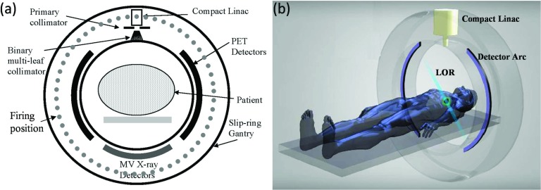
Figure 1 illustrates the EGRT system and treatment geometry, with Fig. 1a showing a cross-sectional view of the detailed system design and Fig. 1b showing a simplified 3D rendering of the treatment geometry. The EGRT system consists of three major components in the same transverse plane mounted on a closed-ring gantry: two arcs of symmetrically opposed positron emission tomography (PET) detectors, a compact linear accelerator (Linac) system, and MV x-ray detectors. The MV x-ray detectors are used for patient setup and the alignment of the PTV. PET detectors span 2 cm in the longitudinal direction and are used to collect LOR data which give instantaneous lines-of-sight to the tumor. The compact Linac is equipped with a primary collimator and a 64-leaf binary multi-leaf collimator (bMLC). The primary collimator defines the slice width of the fan beam of radiation and the rapidly switching bMLC selects among individual beamlets within this fan beam in order to direct radiation along the detected LOR paths. The Linac delivers therapeutic dose at designated points, referred to as firing positions [Fig. 1a], which are equally spaced around the circular gantry (256 firing positions are modeled in this work).
Figure 1.
(a) Cross-sectional diagram of the proposed EGRT system. (b) Snapshot of a LOR being detected in a simplified 3D rendering of the EGRT system.
During treatment, the entire system rapidly rotates around the isocenter with a constant period of 1 s so that while PET detectors are collecting LORs, the Linac beam may align with the LOR paths with a minimal lag time. In the meantime, the patient is slowly translated through the system bore to accomplish a helical dose delivery. Specifically, for each dose delivery point along the treatment helix, the Linac only responds to previously detected LORs that intersect the PTV and the x-ray source with an arc error tolerance of ±0.5°, and which also are recorded within a time window of 500 ms. This set of response rules is referred to as “the basic EGRT algorithm” and ensures accurate tumor tracking. The resultant responded LORs are noted as qualified LORs. A detailed description of the basic EGRT algorithm can be found in our previous work.18 The treatment couch translation speed is constant and selected to cover the longitudinal treatment region that tightly contains the PTV within the treatment time. According to simulations in this work, a typical EGRT treatment can be designed to end within 20 min which yields 1200 or fewer gantry rotations within a couch travel distance of several cm.
EGRT treatment scheme
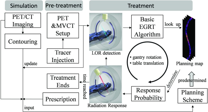
Figure 2 illustrates a summarized flow of the proposed EGRT treatment scheme.
Figure 2.
EGRT treatment scheme consisting of three major components: simulation, pretreatment, and treatment.
The EGRT treatment scheme based on the ITV approach is composed of three major steps: simulation, pretreatment, and treatment using the EGRT algorithms. In simulation, the patient first undergoes PET/CT imaging for contouring and forming the initial treatment plan. Retrospective CT and/or breath-hold CT scans are used to obtain the desired datasets for planning. The maximum intensity projection can be determined from the 4D-CT dataset to obtain the ITV encompassing the full extent of target movement.30, 31 Margins are added to the ITV to define the PTV to account for patient setup error and residual motion uncertainty. The breath-hold CT image, contours, PET image, and dose prescription are used to calculate a planning map via EGRT's planning scheme (discussed in Sec. 2B). On the treatment day, the patient is first administered with a PET radiotracer and waits in a waiting room for the optimal uptake time as in a standard PET imaging protocol. The patient is then positioned on the treatment couch and a simultaneous PET/MVCT scan of short duration (<2 min) is acquired with the EGRT system for alignment and calibration, and additionally to update the planning map (the tracer distribution change within the treatment fraction is assumed to be small). The treatment is composed of two repeating operations, i.e., LOR detection and minimal-lag radiation response. The basic EGRT algorithm sifts out qualified LORs for responses. To achieve the desired intensity modulation, the treatment relies on the planning map to specify the LOR response probabilities and is described below.
The proposed EGRT planning scheme
In this section, we develop a planning scheme for EGRT to achieve specific planning constraints/goals as in conventional optimized treatments. Two types of constraints are typically used in IMRT optimization: one for OARs which limits the maximum dose to a certain percentage of each volume, and one for the PTV which requires the delivery of a prescription dose with high dose conformality. We aim to demonstrate that, as compared with other ITV approaches, the same planning constraints can be met for OARs in EGRT based on the same IMRT plan. At the same time, the GTV dose can be escalated due to inherent tracking, with the dose reduced for the non-GTV portions within the PTV.
The proposed planning scheme is based on EGRT's unique treatment geometry where fast gantry rotation, slow couch translation, and small PET longitudinal coverage coexist. In this geometry, the LORs are approximately detected and responded to in a series of 2D slices. We therefore sample the delivery space into a stack of 2D fan-beam sinograms, referred to as sinogram space. Each bin in sinogram space corresponds to the spatial orientation of a LOR/beamlet detection/response path for a specific slice. Every detected LOR can be mapped into one of the sinogram bins according to a nearest neighbor approximation. Dose modulation can be achieved via applying an LOR response probability to a particular sinogram bin which is used to decide whether to open the corresponding bMLC leaf for a qualified LOR. We refer to the probability distribution across all bins in sinogram space as the planning map.
The overall scheme
Based on the above geometric approximation, the delivered dose in EGRT can be written as
| (1) |
where vector b specifies the total number of qualified LORs for each sinogram bin. Matrix D is a group of beamlet kernels, whose jth column is the vectorized 3D dose distribution resulting from a beamlet with unit intensity along the LOR path specified by the jth sinogram element. Σ is the planning map in the form of a diagonal matrix. Its jth diagonal element is the response probability for the LORs that are mapped into the jth sinogram bin.
The planning map Σ can be further decomposed into three daughter modulation maps as
| (2) |
where ΣA, ΣP, and are all diagonal matrices whose diagonal elements represent modulation for attenuation correction (indicated by superscript A), nonuniform background PET activity normalization (superscript P), and modified IMRT plan (superscript Xm), respectively. Φ is an operator that normalizes the resultant diagonal elements to have a maximum value of 1. The overall modulation contributed by ΣA and ΣP aims to compensate for a nonuniform LOR response distribution before any other modulation is applied. represents the main intensity modulation to be applied in EGRT and is derived from the IMRT plan of a conventional motion-encompassing treatment.
PET activity normalization and attenuation correction
If no modulation is applied and beamlet intensity/duration is constant, the resultant EGRT dose distribution essentially depends on the LOR response distribution or almost equivalently the distribution of detected LORs. It is usually nonuniform due to inhomogeneous PET activity distribution and the nonisotropic attenuation of annihilation photons through the subject, thereby limiting EGRT's capability of incorporating any other intensity modulation.
Inhomogeneous background activity distribution is commonly observed in conventional PET imaging. This can be due to nonspecific and nonuniform uptake in tissue surrounding the target (e.g., FDG uptake in the heart, liver, and other organs, as well as uptake due to inflammation). It yields a nonuniform LOR response distribution since the LOR detection rates are proportional to the aggregate activity along their detection paths. To correct for this effect, we calculate a PET activity normalization map (i.e., ΣP) that is inversely proportional to the LOR detection rates in sinogram space. Specifically, the line integrals of activity are first efficiently precalculated using Siddon's algorithm32 from the diagnostic PET images (and updated from the pretreatment PET scan) for all sinogram bins. The PET activity inside the PTV region is set to zero before projections are calculated to remove bias from uptake in or near the moving GTV. We denote the minimum line integral across all nonzero bins as . For sinogram bin j with associated line integral , its LOR response probability is given as
| (3) |
The same issue arises with the nonisotropic attenuation of annihilation photons, which also results in nonuniform LOR detection rates and therefore a nonuniform radiation response distribution. Likewise, the attenuation effect needs to be corrected before any planning modulation is applied. To do this, the line integrals of attenuation coefficients are first efficiently precalculated based on the planning patient CT images (and updated from the pretreatment MVCT scan) for all sinogram bins. These coefficients are then converted into probabilities to form the attenuation correction map (i.e., ΣA). Let us denote the maximum line integral across all bins as . For sinogram bin j and a line integral , its leaf opening probability is given as
| (4) |
Both Eqs. 3, 4 are determined heuristically and aim to remove their corresponding effects by compensating for lower LOR detection likelihood with higher response probability, and vice versa.
Modified IMRT plan
With the LOR response distribution made uniform through PET activity normalization and attenuation correction, EGRT can now incorporate a traditional IMRT plan to achieve a desired dose distribution. For the clinical patient case, we use the Pinnacle3 workstation (Philips Healthcare, Fitchburg, WI) as our optimization engine. For the digital patient, this task is achieved using an optimization package called MOSEK (Ref. 33) and a beamlet-based optimization algorithm which aims to minimize the L2-norm of the difference between the calculated dose and the prescribed dose for given constraints,34, 35, 36 as in the following formula:
| (5) |
where the index i denotes different structures including PTV and OARs, λi is the relative importance factor,37 each column of matrix Ai is the beamlet kernel corresponding to the ith structure, x is a 1D vector that consists of row-wise concatenations of beamlet intensities for all fields, and di is the vectorized prescribed dose of the ith structure. Nf is the number of fields and Nu is the number of beamlets within a field. β1 is the penalty weight associated with the first regularization term which aims to reduce the complexity within each field while β2 is the penalty weight of the second regularization term used to reduce the intensity difference between adjacent fields (or firing points). After intensity optimization based on formula 5, the resultant fluence maps are converted into the IMRT plan map.
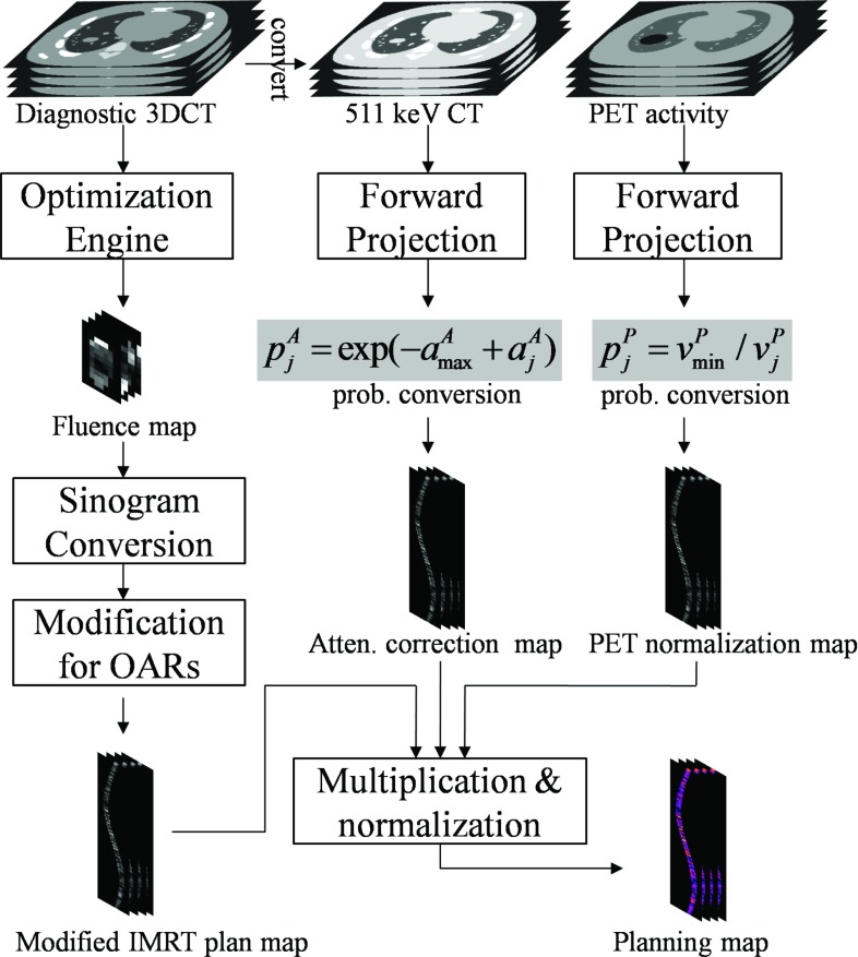
The IMRT plan map is optimized for conventional external beam radiation therapy. It is suboptimal for EGRT since it does not take into account the GTV dose peaking effect in EGRT treatment. Therefore, dose to nearby OARs may be increased relative to the IMRT planning value. To achieve the same planning constraints for OARs, we modify the original transformed IMRT plan map by multiplying an additional probability for sinogram bins whose corresponding spatial orientations intersect the OARs of interest. The specific probabilities are empirically chosen for different OARs within a range of [0.5 1], depending on their proximities to the GTV. A summarized workflow for calculating the EGRT planning map is shown in Fig. 3.
Figure 3.
Calculation of the planning map from three daughter modulation maps that are built in the same sinogram space and which contain the LOR response probability values to account for the corresponding types of modulation. To obtain the modified IMRT plan map, the stack of fluence maps resulting from inverse planning optimization are interpolated and reshaped into sinogram space, and subsequently modified to further suppress dose to nearby OARs. The attenuation correction map is converted from the forward projected CT image based on Eq. 4. Similarly, the PET activity normalization map is calculated from the projection of the diagnostic/pretreatment PET scan, excluding the PTV region, based on Eq. 3. Note that for all modulation maps, only sinogram bins whose corresponding directions intersect the PTV are calculated.
EGRT simulation workflow
Simulation studies are performed on both a digital and a clinical patient with moving tumors in the lung region to investigate the performance of the proposed EGRT treatment. The digital patient (4D XCAT phantom) simulates real patient anatomy with both cardiac and respiratory motion.38 The phantom includes a 4D attenuation distribution for radiation dose calculation and a 4D activity distribution representing typical measured radiotracer uptake values for realistic PET emission simulation using the Geant4 application for tomographic emission [GATE (Ref. 39)] package.40, 41 In the clinical patient case, raw list mode data and reconstructed, binned 4D-PET datasets from a PET/CT Discovery system (GE Healthcare, Waukesha, WI) are retrospectively utilized under an institutional review board (IRB) protocol. The simulation of Linac dose delivery uses a voxel-based MC algorithm (VMC++).42 VMC++ and GATE have been validated against well established MC codes and commercial PET systems, respectively.43, 44, 45
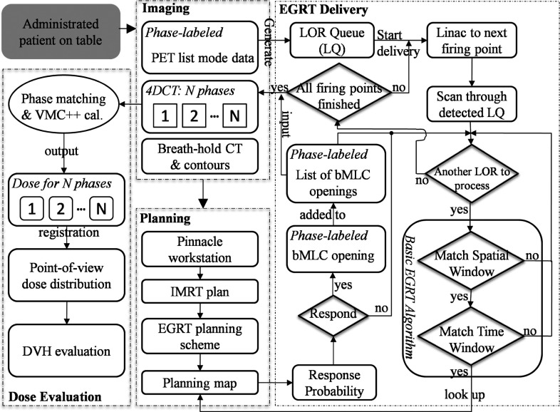
To simulate a dynamic EGRT treatment as a complete motion management scheme, the workflow for the clinical patient scenario is shown in Fig. 4. The entire workflow is segmented into four major sequential steps. The simulation starts from the imaging step where datasets of breath-hold CT, PET list mode, and 4D-CT are acquired. The latter two are collected at the same time using a GE Discovery PET/CT scanner. The CT projection and PET list mode data are sorted and synchronized based on the phases of the breathing trajectory obtained using the real-time position management (RPM) system (Varian Medical Systems, Palo Alto, CA). The imaging data are input into the planning step for the generation of the planning map as in the proposed scheme to be fed into the EGRT delivery segment.
Figure 4.
EGRT simulation workflow for the clinical patient case (starting from the shaded module on the top left). The workflow is divided into four major segments: imaging, planning, EGRT delivery, and dose evaluation, which is different from that for the digital XCAT patient in the imaging and planning steps. In the imaging step, the emission data are simulated using GATE and the phase information is known a priori. In the planning step, the IMRT plan is optimized using MOSEK and the inverse planning algorithms as discussed in Sec. 2B. Note that the PTV intersection rule is implicitly implemented in the planning scheme.
The EGRT delivery step simulates the dynamic aspect of the EGRT treatment where tumor tracking and planning modulation are achieved. It starts with the conversion of the phase-labeled raw PET list mode data into the LOR queue where each entry includes its timestamp, 3D Cartesian coordinates of the two LOR end-points, and phase number. When the dose delivery starts, the Linac goes through all firing points sequentially along the treatment helix. At each firing point, it scans through the LOR queue that can be detected by the PET detectors at its current position and then determines the response probability for each individual LOR based on the basic EGRT algorithm and the nearest bin in the planning map. The resultant bMLC opening will be consequently added to the list of bMLC openings to be output once all firing points have been processed. This list specifies the complete set of information of the beamlet responses during the treatment including the spatial coordinates of the firing points, the leaf numbers that are opened, and the phase number of the 4D-CT at the time a leaf is opened.
Each entry of the bMLC openings list will be matched with the 4D-CT dataset based on its phase for subsequent VMC++ calculation in the dose evaluation step. The dose for each phase is obtained via summation of all the beamlet responses for the same phase. To calculate the total dose of a moving structure, dose maps of different phases are registered to the same reference phase through rigid image registration. The multiple dose maps are then summed to produce a point-of-view map relative to the moving structure, resulting in its accumulated total dose during the entire treatment.
Performance evaluation
For performance evaluation, 3D IMRT treatments are designed for both the digital and clinical patient cases. The OAR planning limits are based on the values recommended by the quantitative analysis of normal tissue effects in the clinic (QUANTEC) (Ref. 46) and Radiation Therapy Oncology Group 0236 (Ref. 1) for digital and clinical patients, respectively. 256 fields are used to correspond with the EGRT treatment geometry. The resultant optimized fluence maps are used to calculate a 3D divergent dose distribution. Helical IMRT (hIMRT) treatments are also simulated as comparisons to both 3D IMRT and EGRT treatments. On one hand, hIMRT treatments intend to replicate the 3D IMRT treatment in the helical treatment geometry with a different source-to-axis distance (SAD) by interpolating and reshaping the same IMRT plans. On the other hand, the hIMRT treatments use nearly the same system settings (i.e., the same bMLC system, the same number of firing positions, the same SAD, and the same firing geometry with a more suitable helical pitch) as EGRT treatments. The main difference is that EGRT opens the leaves according to the probability scheme using LOR-based guidance, while the hIMRT treatments deliver the dose with deterministic plan intensities as the 3D IMRT treatments. The purpose of including hIMRT in the current study is to understand if any of the performance benefits of EGRT over 3D IMRT are due to the helical geometry of EGRT. The evaluation details pertaining to the individual studies are discussed below.
Digital XCAT patient
In the XCAT patient case, respiratory motion and heart motion are modeled with periods of 4.2 and 1 s, respectively, sampled in 12 phases. The GTV is modeled using an ellipsoid with a set of semiaxis lengths of 1.5, 1, 1.5 cm and placed in the right lung. The GTV motion path is based on the XCAT built-in 3D periodic tumor motion trajectory with typical lung motion behavior and peak-peak amplitudes of 16.6, 3.5, and 0.02 mm for superior-inferior (SI), anterior-posterior (AP), lateral-medial (LM) directions, respectively. Structures are contoured based on the phantom masks. The ITV volume is calculated as the union set of all GTV voxels. The PTV is designed as a 6 mm uniform extension of the ITV. The IMRT plan is optimized with a prescription of 70 Gy to 95% of the PTV. The couch position covers a treatment range of 7 cm containing the whole PTV. The treatment time is 1200 s, resulting in a translation speed of approximately 0.006 cm/s. The first phase of the generated 511 keV attenuation phantom, 110 keV attenuation phantom, and PET activity phantom are used for the calculation of the attenuation correction map, IMRT plan map, and PET normalization map, respectively. The tumor, lung, and background activity uptake ratio is set to be 8:0.5:1 with the base background activity as 3 kBq/cc. The phantom geometry can be seen in Fig. 6.
Figure 6.
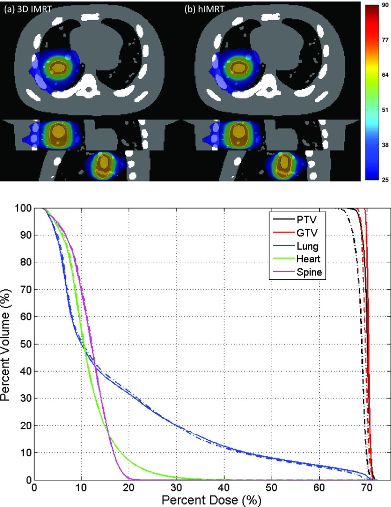
Dose distribution and associated DVH comparison of 3D IMRT [(a), solid lines] and hIMRT [(b), dashed-dotted lines]. The PTV and GTV are contoured using solid lines in the dose distributions.
Clinical patient
The clinical patient datasets of 4D-CT, 4D-PET, and breath-hold CT are retrospectively collected at the Stanford Cancer Institute under an IRB protocol. The tumor is staged as a metastasis of breast cancer in the left lung region, with a GTV size of 3.33 cm3 averaged over all six motion phases. The tumor motion has estimated peak-peak amplitudes of 8.5, 4.5, and 2.5 mm for SI, AP, and LM directions, respectively. The raw PET list mode data is corrected with a 1.02 cm systematic shift in the longitudinal direction after manual registration of the 4D-PET and 4D-CT volume using RT Image.47 Structure contours including the PTV that contains the GTV motion are made by a designated specialist on the breath-hold CT, which are used for the IMRT plan modulation map calculation in the Pinnacle3 workstation. In observation of the spine's proximity to the GTV, the IMRT plan is optimized with a prescription of 54 Gy to 95% of the PTV. The breath-hold CT is converted into a 511 keV CT volume for the attenuation correction map calculation. To obtain the PET activity normalization map, the first phase of the reconstructed 4D-PET volume is interpolated to coincide with the breath-hold CT volume in terms of resolution and position. The couch position covers a treatment range of 9 cm and the treatment time is 1200 s, resulting in a translation speed of 0.0075 cm/s. Since only 5 min of PET data are acquired per bed position, PET list mode data are looped with simulated FDG decay for reuse. GTV is manually registered to each 4D-CT phase similarly using RT Image to evaluate its accumulated dose during the entire treatment. The patient geometry can be seen in Fig. 9.
Figure 9.
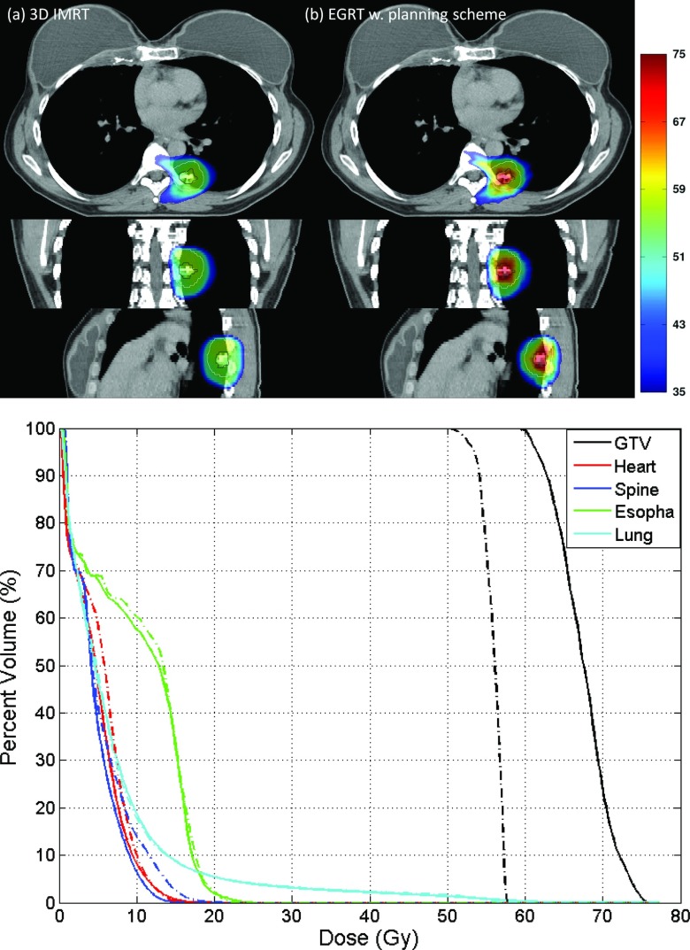
Comparison of 3D IMRT [(a), dashed-dotted line] and EGRT with planning scheme [(b), solid line] for the clinical patient case.
Figure 5 illustrates an example of the fluence maps output from Pinnacle3 and the IMRT plan map converted from the fluence maps. A summary of the main simulation parameters for performance evaluation is shown in Table 1.
Figure 5.
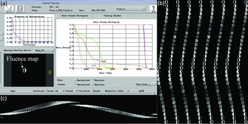
Calculation of the IMRT plan map using Pinnacle3. (a) Pinnacle3 interface for inverse planning. (b) 256-field fluence maps. (c) The central sinogram of the IMRT plan map.
Table 1.
A summary of major simulation parameters.
| Parameter | Value | Parameter | Value | |
|---|---|---|---|---|
| EGRT/hIMRT | PET detector extent | 2 cm | Leaf aperture at iso (x-y) | 0.5 cm |
| PET detector coverage | 2 × 90° arc | Leaf aperture at iso (z) | 0.5 cm | |
| PET ring radius | 50 cm | Source intersection tolerance | ±0.5° arc | |
| Linac rotating frequency | 1 Hz | Response time window | 500 ms | |
| Linac radius | 60 cm | hIMRT pitch | 0.4 | |
| Collimator radius | 50 cm | Radiotracer | FDG | |
| Collimator leaves | 64 | Firing positions | 256 | |
| 3D IMRT | SAD | 100 cm | Field number | 256 |
| GATE | Version | V5.0.0.p01 | Light decay time (LSO) | 40 ns |
| Coincidence window | 10 ns | Energy resolution | 0.26 | |
| Scatter threshold (keV) | 350, 650 | Multiple coincidence policy | TakeWinnerofGoods | |
| XCAT phantom | Respiration period | 4.2 s | Phantom size | 256 × 256 × 35 |
| Respiration phases | 12 | Voxel resolution | 2 × 2 × 2 mm3 | |
| Couch travel range | 7 cm | Dose grid resolution | 4 × 4 × 4 mm3 | |
| GTV size | 9.40 cm3 | Sinogram bin size | 256 × 64 × 35 | |
| ITV size | 17.01 cm3 | Tracer uptake ratio | 8:0.5:1 | |
| ITV to PTV margin | 6 mm | Background activity | 3 kBq/cc | |
| Treatment time | 1200 s | IMRT field resolution | 5 × 2 mm2 | |
| Prescription dose | 70 Gy | |||
| Clinical patient | Respiration phases | 6 | 4D-CT size | 512 × 512 × 40 |
| Average GTV size | 3.33 cm3 | 4D-CT resolution | 0.98 × 0.98 × 2.5 mm3 | |
| Couch travel range | 9 cm | Breath-hold resolution | 0.98 × 0.98 × 1.25 mm3 | |
| ITV size | 5.97 cm3 | Dose grid resolution | 3.92 × 3.92 × 2.5 mm3 | |
| Treatment time | 1200 s | Sinogram bin size | 256 × 64 × 40 | |
| IMRT field resolution | 5 × 2.5 mm2 | Tracer uptake SUV | ∼6 (GTV), ∼1(Bg.) | |
| PTV size | 16.8 cm3 | Prescription dose | 54 Gy |
RESULTS
Digital XCAT patient
Figure 6 shows the dose distribution and dose volume histogram (DVH) comparison of 3D IMRT and hIMRT treatment using the same treatment plan. Motion is not simulated in this case. The dose distribution is normalized to have the same mean lung dose. The slightly inferior performance of hIMRT, when compared to 3D IMRT, is likely due to delivering a divergent IMRT plan in a helical geometry. The SAD difference also contributes to this difference but the influence is small. Overall, the dose performance of 3D IMRT and hIMRT is similar for both GTV and OARs. Since hIMRT treatment uses exactly the same treatment geometry as EGRT, differences in performance between 3D IMRT and EGRT should be largely independent of the change from a divergent to helical geometry.
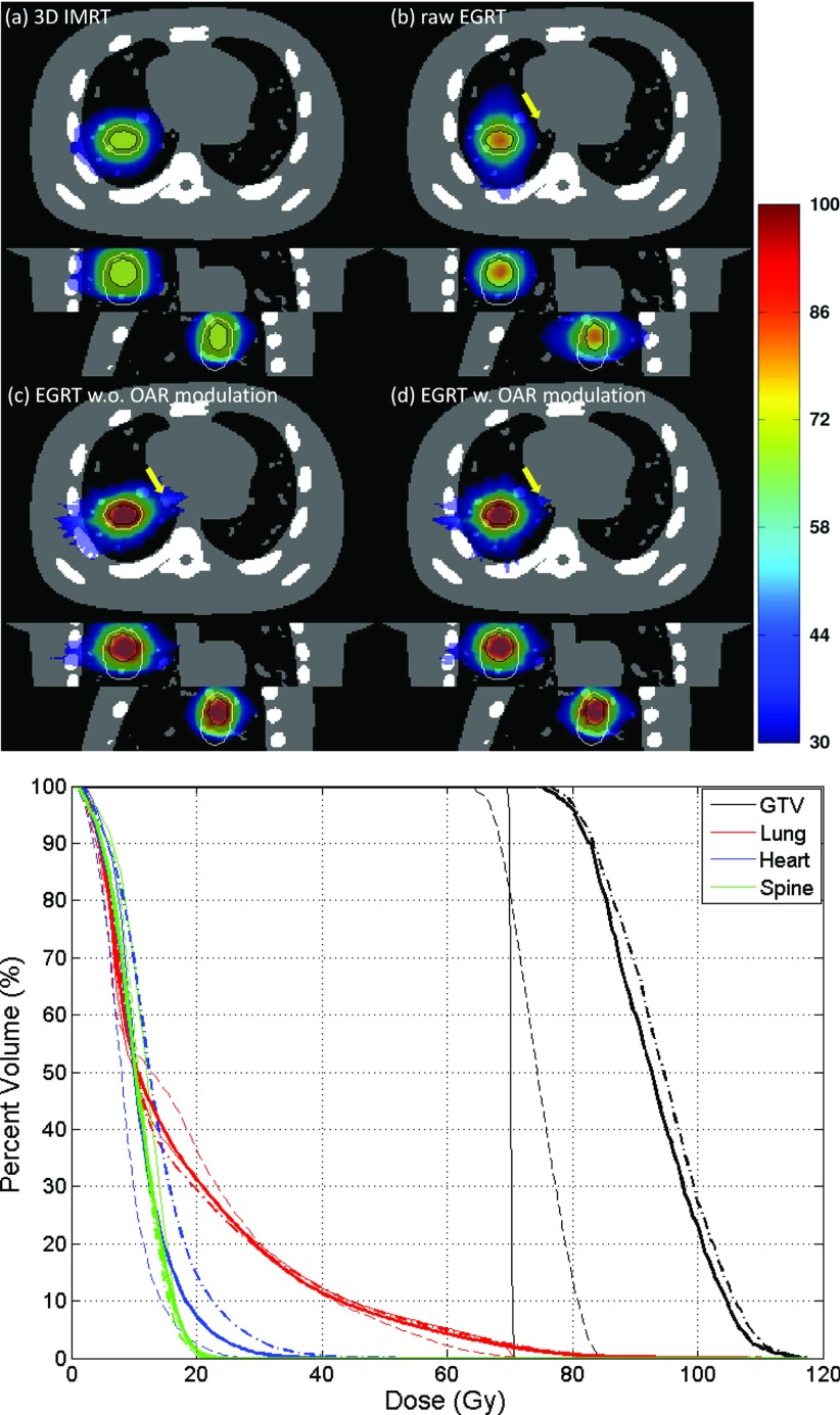
Figure 7 illustrates the GTV point-of-view dose maps assembled from all 12 motion phases for 3D IMRT, raw EGRT, and planning scheme-implemented EGRT without or with modification for additional modulation to the heart and spine, as well as the associated DVH curves. The dose distribution is normalized to have the same mean lung dose. 133 288, 17 818, and 15 805 beamlet responses have been generated for the three EGRT treatments, respectively. Without the proper planning scheme implemented, raw EGRT cannot outperform 3D IMRT due to the fact that dose is distributed more toward the lung rather than the heart. EGRT with the planning scheme absent of additional modification for OARs is able to deliver a better dose distribution to the target, although at the price of increased heart dose due to its proximity to the GTV. When additional modulation is present to account for the dose peaking effect, heart dose is suppressed [see arrow-pointed dose distributions in Fig. 7c, 7d]. The corresponding DVH comparison shows that dose increases to nearby OARs can be suppressed with additional modification to the original IMRT map with minor dose degradation to the target. Compared with the 3D IMRT treatment, EGRT with all corrections achieves a 15.1% relative increase in dose to 95% of the GTV and a 31.8% increase to 50% of the GTV while the OAR doses are kept similar or lower for EGRT.
Figure 7.
Comparison of 3D IMRT [(a), thin solid line], raw EGRT [(b), thin dashed line], and EGRT with planning scheme that does not include [(c), dashed-dotted line] and includes [(d), thick solid line] additional OAR modulation. Note that the heart curves for (a) and (d) are mostly overlapping.
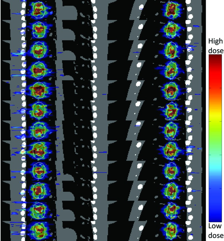
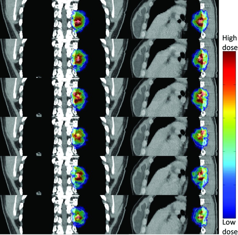
Figure 8 depicts the dose maps of all 12 simulated phases for EGRT with complete planning scheme [i.e., Fig. 7d] in both coronal and sagittal views. The results indicate that in spite of the dose “noise” introduced due to the reduced number of beamlet responses, tumor tracking is largely preserved.
Figure 8.
Tumor tracking of EGRT with the complete planning scheme. Both PTV and GTV are contoured to show the dose tracking. The dose map of each phase is displayed with an individually optimized window.
Clinical patient
Figure 9 shows the comparison of 3D IMRT and planning scheme implemented EGRT with additional modulation on spine, heart, and esophagus. 32 086 beamlet responses have been generated for the EGRT treatment. Compared with the 3D IMRT treatment, EGRT yields a 15.2% relative increase in dose to 95% of the GTV and a 20.7% increase to 50% of the GTV while OAR doses are kept similar or lower. Note that the challenging sparing of spine achieved in 3D IMRT is retained in EGRT with the proposed planning scheme.
Figure 10 shows the dose maps of all six simulated phases for EGRT treatment in both coronal and sagittal views. Unlike the XCAT patient case in which PET data and CT phases are ideally matched a priori, such matching in the patient case is not guaranteed due to motion and breathing changes in the sequential PET/CT scan and the uncertainties in PET and CT phase sorting based on external surrogate tracking. Nevertheless, the results still show that tumor tracking is preserved when the planning scheme is incorporated.
Figure 10.
Tumor tracking of a breast cancer lung metastasis under EGRT with the planning scheme. The PTV and GTV are contoured for positional reference and target motion delineation, respectively. The dose maps are displayed with the same window [0.5 0.85] relative to the maximum GTV dose across all phases.
DISCUSSION
In this work, we implement the EGRT concept as a complete motion management scheme that is able to incorporate IMRT plan modulation. Due to the inherent tracking capability of EGRT, the proposed treatment can significantly improve the dose performance of the conventional ITV approach while still preserving its ease of implementation in each step of the imaging, planning, and delivery therapy chain.
In the current implementation of EGRT, a few items require further consideration and discussion. The planning scheme entails the discarding of a portion of beamlet responses. Dose maps showing the tumor tracking of each phase can therefore be “noisy” as shown in the XCAT patient case. This effect is less pronounced with a smaller number of phases and higher overall activity levels as in the clinical patient case. In either scenario, the point-of-view dose map is representative of the effective dose for each structure and this is what is used to calculate the DVH curves.
ERGT favors a treatment plan that spans all angles to make full use of LOR data. For example, a volumetric modulated arc therapy (VMAT) plan is a good fit for this purpose. In the evaluation studies, a 256-field IMRT plan is used instead due to the fact that it corresponds well with EGRT's 256-firing-position geometry enabling a direct comparison and provides a good approximation of a VMAT plan. Since the EGRT helical dose delivery geometry provides more degrees of freedom due to the large number of fields used,48 EGRT possesses increased flexibility in planning a treatment compared with a conventional step-and-shoot IMRT treatment. Highly efficient IMRT planning methods tailored for EGRT delivery that make full use of such flexibility can be developed to improve EGRT's performance. Additionally, the intensity/duration of the beamlet responses can also be modulated to give further flexibility for EGRT to incorporate planning modulation.
The proposed planning scheme provides the insight and basis for the future development of a fully characterized EGRT planning system. In order to achieve desired intensity dose modulation without interference, corrections for attenuation and nonuniform PET activity are necessary. Moreover, in spite of the fact that the EGRT delivery relies on the statistical detection of LORs, a deterministic intensity modulation can be approximately achieved. Modifications to the IMRT plan ensure that clinical constraints for OARs can be met. The achievement of dose conformality to the GTV remains an issue for EGRT. The dose peaking effect is a natural result of the radiation “backprojection” principle in EGRT. This technique may be well suited to situations in which an integrated boost dose is desirable.49
The current proposed planning scheme illustrates a general way to incorporate intensity modulation into EGRT. Although it is evaluated within the context of motion-encompassing methods, the planning scheme can be applied for other applications including gating and tracking methods without major modification to similarly achieve GTV dose escalation. This is due to the fact that the plan intensity weights that would have been delivered to the margins are effectively reduced in EGRT. The current design of the planning scheme assumes the tumor dynamic changes (e.g., tumor size, PET tracer uptake distribution) remain small during the treatment course as in the hypofractionated treatment scheme.50, 51 When EGRT is applied in a conventionally fractionated scheme, such changes can be monitored via the pretreatment PET/MVCT scan. The planning scheme and/or EGRT treatment scheme can then be modified to enable personalized radiation treatments based on the patient-specific51 dynamic biological information. For example, a progressive fraction dose scheme can be applied in accordance with progressive metabolic disease, while for tumors showing complete metabolic response, EGRT treatment can be switched to conventional therapy or even stopped. Note that certain tumor changes may have already been implicitly taken into account within the current planning scheme. For instance, the tumor may shrink during the treatment course. Since the planning scheme allows EGRT to concentrate the dose to just the GTV, normal tissue sparing will likely be better if the GTV size is reduced, or equivalently the dose to the GTV can be further increased.
Finally, it should be noted that in the evaluation scheme, it is implicitly assumed that the motion can be or should be divided into phases. However in fact, tumor motion can be quite irregular, even for a lung tumor. Therefore, any 4D tracking based methods with the phase division assumption are subject to the challenges of motion irregularity during the imaging or delivery process. In contrast, the tumor tracking and proposed planning scheme in the EGRT treatment is not limited by the phase theory. EGRT therefore provides a potential solution to deal with different types of motion, periodic or random, encountered over all treatment sites. Also note that in the simulation study presented in this work, 4D-CT is only acquired for evaluation purposes. In an actual EGRT treatment, a slow CT can be used to obtain the ITV instead, thereby avoiding the increased dose and complexity of 4D-CT imaging. In fact, each step of imaging, planning, and delivery of the proposed EGRT treatment can essentially be regarded as 3D, with the tumor tracking taken care of automatically. The complexities and uncertainties associated with 4D imaging and delivery can be significantly reduced or in some cases eliminated.
CONCLUSIONS
With the proposed planning scheme, EGRT outperforms the conventional ITV approach with a dose increase of more than 15% to the moving target while the dose levels of OARs are kept similar or reduced. With the capabilities of achieving both tumor tracking and intensity modulation, EGRT has the potential to enable an effective implementation of 4D radiation therapy with true biological targeting and guidance.
ACKNOWLEDGMENTS
This work is supported by Georgia Institute of Technology new faculty startup fund, RefleXion Medical, and the National Cancer Institute (R43CA153466). S.R.M., A.S.N. and L.Z. have financial interest in RefleXion Medical. B.W.L. receives speaking honoraria from Varian and research support from Varian, Philips, and RaySearch Labs. The authors thank Sue Wallace, Michael Kaus, Ying Xiong, Hari Gopalakrishnan, and Matthieu Bal from Philips Radiation Oncology Systems for providing a Pinnacle3 workstation and technical support. The authors thank Frédéric Tessier and the National Research Council of Canada for providing the VMC++ software, and CliQr Technologies for providing cloud computing resources. The authors would also like to thank Paul Segars, Youngho Seo, Xun Jia, Norbert Pelc, David Townsend, Charles Pelizzari, Chin-Tu Chen, Ralph Weichselbaum, Paul Keall, and James Welsh for generous help and useful discussions.
References
- Timmerman R., Paulus R., Galvin J., Michalski J., Straube W., Bradley J., Fakiris A., Bezjak A., Videtic G., and Johnstone D., “Stereotactic body radiation therapy for inoperable early stage lung cancer,” J. Am. Med. Assoc. 303, 1070–1076 (2010). 10.1001/jama.2010.261 [DOI] [PMC free article] [PubMed] [Google Scholar]
- Baumann P., Nyman J., Hoyer M., Wennberg B., Gagliardi G., Lax I., Drugge N., Ekberg L., Friesland S., and Johansson K. A., “Outcome in a prospective phase II trial of medically inoperable stage I non-small-cell lung cancer patients treated with stereotactic body radiotherapy,” J. Clin. Oncol. 27, 3290–3296 (2009). 10.1200/JCO.2008.21.5681 [DOI] [PubMed] [Google Scholar]
- King C. R., Brooks J. D., Gill H., Pawlicki T., Cotrutz C., and Presti J. C., “Stereotactic body radiotherapy for localized prostate cancer: Interim results of a prospective phase II clinical trial,” Int. J. Radiat. Oncol., Biol., Phys. 73, 1043–1048 (2009). 10.1016/j.ijrobp.2008.05.059 [DOI] [PubMed] [Google Scholar]
- Grills I. S., Mangona V. S., Welsh R., Chmielewski G., McInerney E., Martin S., Wloch J., Ye H., and Kestin L. L., “Outcomes after stereotactic lung radiotherapy or wedge resection for stage I non-small-cell lung cancer,” J. Clin. Oncol. 28, 928–935 (2010). 10.1200/JCO.2009.25.0928 [DOI] [PubMed] [Google Scholar]
- Palma D., Visser O., Lagerwaard F. J., Belderbos J., Slotman B., and Senan S., “Treatment of stage I NSCLC in elderly patients: A population-based matched-pair comparison of stereotactic radiotherapy versus surgery,” Radiother. Oncol. 101, 240–244 (2011). 10.1016/j.radonc.2011.06.029 [DOI] [PubMed] [Google Scholar]
- Rosu M. and Hugo G. D., “Advances in 4D radiation therapy for managing respiration: Part II—4D treatment planning,” Z. Med. Phys. 22, 272–280 (2012). 10.1016/j.zemedi.2012.06.011 [DOI] [PMC free article] [PubMed] [Google Scholar]
- Seppenwoolde Y., Shirato H., Kitamura K., Shimizu S., van Herk M., Lebesque J. V., and Miyasaka K., “Precise and real-time measurement of 3D tumor motion in lung due to breathing and heartbeat, measured during radiotherapy,” Int. J. Radiat. Oncol., Biol., Phys. 53, 822–834 (2002). 10.1016/S0360-3016(02)02803-1 [DOI] [PubMed] [Google Scholar]
- Riboldi M., Sharp G., Baroni G., and Chen G., “Four-dimensional targeting error analysis in image-guided radiotherapy,” Phys. Med. Biol. 54, 5995–6008 (2009). 10.1088/0031-9155/54/19/022 [DOI] [PubMed] [Google Scholar]
- Shirato H., Suzuki K., Sharp G. C., Fujita K., Onimaru R., Fujino M., Kato N., Osaka Y., Kinoshita R., and Taguchi H., “Speed and amplitude of lung tumor motion precisely detected in four-dimensional setup and in real-time tumor-tracking radiotherapy,” Int. J. Radiat. Oncol., Biol., Phys. 64, 1229–1236 (2006). 10.1016/j.ijrobp.2005.11.016 [DOI] [PubMed] [Google Scholar]
- Stevens C. W., Munden R. F., Forster K. M., Kelly J. F., Liao Z., Starkschall G., Tucker S., and Komaki R., “Respiratory-driven lung tumor motion is independent of tumor size, tumor location, and pulmonary function,” Int. J. Radiat. Oncol., Biol., Phys. 51, 62–68 (2001). 10.1016/S0360-3016(01)01621-2 [DOI] [PubMed] [Google Scholar]
- Slotman B. J., Lagerwaard F. J., and Senan S., “4D imaging for target definition in stereotactic radiotherapy for lung cancer,” Acta Oncol. 45, 966–972 (2006). 10.1080/02841860600902817 [DOI] [PubMed] [Google Scholar]
- D’Souza W. D., Nazareth D. P., Zhang B., Deyoung C., Suntharalingam M., Kwok Y., Yu C. X., and Regine W. F., “The use of gated and 4D CT imaging in planning for stereotactic body radiation therapy,” Med. Dosim. 32, 92–101 (2007). 10.1016/j.meddos.2007.01.006 [DOI] [PubMed] [Google Scholar]
- Benedict S. H., Yenice K. M., Followill D., Galvin J. M., Hinson W., Kavanagh B., Keall P., Lovelock M., Meeks S., and Papiez L., “Stereotactic body radiation therapy: The report of AAPM Task Group 101,” Med. Phys. 37, 4078–4101 (2010). 10.1118/1.3438081 [DOI] [PubMed] [Google Scholar]
- Keall P. J., Mageras G. S., Balter J. M., Emery R. S., Forster K. M., Jiang S. B., Kapatoes J. M., Low D. A., Murphy M. J., and Murray B. R., “The management of respiratory motion in radiation oncology report of AAPM Task Group 76,” Med. Phys. 33, 3874–3900 (2006). 10.1118/1.2349696 [DOI] [PubMed] [Google Scholar]
- Roland T., Hales R., McNutt T., Wong J., Simari P., and Tryggestad E., “A method for deriving a 4D-interpolated balanced planning target for mobile tumor radiotherapy,” Med. Phys. 39, 195–205 (2012). 10.1118/1.3666774 [DOI] [PubMed] [Google Scholar]
- Wolthaus J. W. H., Sonke J. J., van Herk M., Belderbos J. S. A., Rossi M. M. G., Lebesque J. V., and Damen E. M. F., “Comparison of different strategies to use four-dimensional computed tomography in treatment planning for lung cancer patients,” Int. J. Radiat. Oncol., Biol., Phys. 70, 1229–1238 (2008). 10.1016/j.ijrobp.2007.11.042 [DOI] [PubMed] [Google Scholar]
- Marks L. B., “Dosimetric predictors of radiation-induced lung injury,” Int. J. Radiat. Oncol., Biol., Phys. 54, 313–316 (2002). 10.1016/S0360-3016(02)02928-0 [DOI] [PubMed] [Google Scholar]
- Fan Q., Nanduri A., Mazin S., and Zhu L., “Emission guided radiation therapy for lung and prostate cancers: A feasibility study on a digital patient,” Med. Phys. 39, 7140–7152 (2012). 10.1118/1.4761951 [DOI] [PMC free article] [PubMed] [Google Scholar]
- Fan Q. and Zhu L., “Emission guided radiation therapy: A simulation study of treatment without margin,” Med. Phys. 37, 3330–3331 (2010). 10.1118/1.3469024 [DOI] [Google Scholar]
- Fan Q., Nanduri A., Zhu L., and Mazin S., “Emission guided radiation therapy: A simulation study of lung cancer treatment with automatic tumor tracking using a 4D digital patient model,” Med. Phys. 39, 3922 (2012). 10.1118/1.4736008 [DOI] [PMC free article] [PubMed] [Google Scholar]
- Mazin S., Nanduri A., and Pelc N., “Emission guided radiation therapy system: A feasibility study,” Med. Phys. 37, 3145 (2010). 10.1118/1.3468226 [DOI] [PMC free article] [PubMed] [Google Scholar]
- Xu T., Wong J. T., Shikhaliev P. M., Ducote J. L., Al-Ghazi M. S., and Molloi S., “Real-time tumor tracking using implanted positron emission markers: Concept and simulation study,” Med. Phys. 33, 2598–2609 (2006). 10.1118/1.2207213 [DOI] [PubMed] [Google Scholar]
- Chamberland M., Wassenaar R., Spencer B., and Xu T., “Performance evaluation of real-time motion tracking using positron emission fiducial markers,” Med. Phys. 38, 810–819 (2011). 10.1118/1.3537206 [DOI] [PubMed] [Google Scholar]
- Kubo H. D. and Hill B. C., “Respiration gated radiotherapy treatment: A technical study,” Phys. Med. Biol. 41, 83–91 (1996). 10.1088/0031-9155/41/1/007 [DOI] [PubMed] [Google Scholar]
- Shirato H., Shimizu S., Kunieda T., Kitamura K., van Herk M., Kagei K., Nishioka T., Hashimoto S., Fujita K., and Aoyama H., “Physical aspects of a real-time tumor-tracking system for gated radiotherapy,” Int. J. Radiat. Oncol., Biol., Phys. 48, 1187–1195 (2000). 10.1016/S0360-3016(00)00748-3 [DOI] [PubMed] [Google Scholar]
- McQuaid D. and Webb S., “IMRT delivery to a moving target by dynamic MLC tracking: Delivery for targets moving in two dimensions in the beam's eye view,” Phys. Med. Biol. 51, 4819–4839 (2006). 10.1088/0031-9155/51/19/007 [DOI] [PubMed] [Google Scholar]
- Sawant A., Venkat R., Srivastava V., Carlson D., Povzner S., Cattell H., and Keall P., “Management of three-dimensional intrafraction motion through real-time DMLC tracking,” Med. Phys. 35, 2050–2061 (2008). 10.1118/1.2905355 [DOI] [PMC free article] [PubMed] [Google Scholar]
- Bel A., Petrascu O., Van de Vondel I., Coppens L., Linthout N., Verellen D., and Storme G., “A computerized remote table control for fast on-line patient repositioning: Implementation and clinical feasibility,” Med. Phys. 27, 354–358 (2000). 10.1118/1.598838 [DOI] [PubMed] [Google Scholar]
- Wiersma R. D., Wen Z., Sadinski M., Farrey K., and Yenice K. M., “Development of a frameless stereotactic radiosurgery system based on real-time 6D position monitoring and adaptive head motion compensation,” Phys. Med. Biol. 55, 389–401 (2010). 10.1088/0031-9155/55/2/004 [DOI] [PubMed] [Google Scholar]
- Bradley J. D., Nofal A. N., El Naqa I. M., Lu W., Liu J., Hubenschmidt J., Low D. A., Drzymala R. E., and Khullar D., “Comparison of helical, maximum intensity projection (MIP), and averaged intensity (AI) 4D CT imaging for stereotactic body radiation therapy (SBRT) planning in lung cancer,” Radiother. Oncol. 81, 264–268 (2006). 10.1016/j.radonc.2006.10.009 [DOI] [PubMed] [Google Scholar]
- Underberg R. W. M., Lagerwaard F. J., Slotman B. J., Cuijpers J. P., and Senan S., “Use of maximum intensity projections (MIP) for target volume generation in 4DCT scans for lung cancer,” Int. J. Radiat. Oncol., Biol., Phys. 63, 253–260 (2005). 10.1016/j.ijrobp.2005.05.045 [DOI] [PubMed] [Google Scholar]
- Siddon R. L., “Fast calculation of the exact radiological path for a three-dimensional CT array,” Med. Phys. 12, 252–255 (1985). 10.1118/1.595715 [DOI] [PubMed] [Google Scholar]
- http://www.mosek.com/.
- Zhu L., Lee L., Ma Y., Ye Y., Mazzeo R., and Xing L., “Using total-variation regularization for intensity modulated radiation therapy inverse planning with field-specific numbers of segments,” Phys. Med. Biol. 53, 6653–6672 (2008). 10.1088/0031-9155/53/23/002 [DOI] [PubMed] [Google Scholar]
- Zhu L. and Xing L., “Search for IMRT inverse plans with piecewise constant fluence maps using compressed sensing techniques,” Med. Phys. 36, 1895–1905 (2009). 10.1118/1.3110163 [DOI] [PMC free article] [PubMed] [Google Scholar]
- Zhu L., Niu T., Choi K., and Xing L., “Total-variation regularization based inverse planning for intensity modulated arc therapy,” Technol. Cancer. Res. Treat. 11, 149–162 (2012). [DOI] [PubMed] [Google Scholar]
- Xing L., Li J., Donaldson S., Le Q., and Boyer A., “Optimization of importance factors in inverse planning,” Phys. Med. Biol. 44, 2525–2536 (1999). 10.1088/0031-9155/44/10/311 [DOI] [PubMed] [Google Scholar]
- Segars W., Mahesh M., Beck T., Frey E., and Tsui B., “Realistic CT simulation using the 4D XCAT phantom,” Med. Phys. 35, 3800–3808 (2008). 10.1118/1.2955743 [DOI] [PMC free article] [PubMed] [Google Scholar]
- http://www.opengatecollaboration.org/.
- Strulab D., Santin G., Lazaro D., Breton V., and Morel C., “GATE (Geant4 application for tomographic emission): A PET/SPECT general-purpose simulation platform,” Nucl. Phys. B, Proc. Suppl. 125, 75–79 (2003). 10.1016/S0920-5632(03)90969-8 [DOI] [Google Scholar]
- Jan S., Santin G., Strul D., Staelens S., Assie K., Autret D., Avner S., Barbier R., Bardies M., and Bloomfield P., “GATE: A simulation toolkit for PET and SPECT,” Phys. Med. Biol. 49, 4543–4561 (2004). 10.1088/0031-9155/49/19/007 [DOI] [PMC free article] [PubMed] [Google Scholar]
- Kawrakow I., “Improved modeling of multiple scattering in the voxel Monte Carlo model,” Med. Phys. 24, 505–517 (1997). 10.1118/1.597933 [DOI] [PubMed] [Google Scholar]
- Kawrakow I., “VMC++, electron and photon Monte Carlo calculations optimized for radiation treatment planning,” in Advanced Monte Carlo for Radiation Physics, Particle Transport Simulation and Applications: Proceedings of the Monte Carlo 2000 Meeting (Springer-Verlag, Berlin, 2001), pp. 229–236.
- Kawrakow I., Fippel M., and Friedrich K., “3D electron dose calculation using a voxel based Monte Carlo algorithm (VMC),” Med. Phys. 23, 445–457 (1996). 10.1118/1.597673 [DOI] [PubMed] [Google Scholar]
- Schmidtlein C. R., Kirov A. S., Nehmeh S. A., Erdi Y. E., Humm J. L., Amols H. I., Bidaut L. M., Ganin A., Stearns C. W., and McDaniel D. L., “Validation of GATE Monte Carlo simulations of the GE advance/discovery LS PET scanners,” Med. Phys. 33, 198–208 (2006). 10.1118/1.2089447 [DOI] [PubMed] [Google Scholar]
- Marks L. B., Yorke E. D., Jackson A., Ten Haken R. K., Constine L. S., Eisbruch A., Bentzen S. M., Nam J., and Deasy J. O., “Use of normal tissue complication probability models in the clinic,” Int. J. Radiat. Oncol., Biol., Phys. 76, S10–S19 (2010). 10.1016/j.ijrobp.2009.07.1754 [DOI] [PMC free article] [PubMed] [Google Scholar]
- http://rtimage.sourceforge.net/.
- Bichay T., Cao D., and Orton C. G., “Helical tomotherapy will ultimately replace linear accelerator based IMRT as the best way to deliver conformal radiotherapy,” Med. Phys. 35, 1625–1628 (2008). 10.1118/1.2885365 [DOI] [PubMed] [Google Scholar]
- Dogan N., King S., Emami B., Mohideen N., Mirkovic N., Leybovich L. B., and Sethi A., “Assessment of different IMRT boost delivery methods on target coverage and normal-tissue sparing,” Int. J. Radiat. Oncol., Biol., Phys. 57, 1480–1491 (2003). 10.1016/S0360-3016(03)01569-4 [DOI] [PubMed] [Google Scholar]
- Henderson M. A., Hoopes D. J., Fletcher J. W., Lin P.-F., Tann M., Yiannoutsos C. T., Williams M. D., Fakiris A. J., McGarry R. C., and Timmerman R. D., “A pilot trial of serial 18F-fluorodeoxyglucose positron emission tomography in patients with medically inoperable stage I non-small-cell lung cancer treated with hypofractionated stereotactic body radiotherapy,” Int. J. Radiat. Oncol., Biol., Phys. 76, 789–795 (2010). 10.1016/j.ijrobp.2009.02.051 [DOI] [PMC free article] [PubMed] [Google Scholar]
- van Baardwijk A., Bosmans G., Dekker A., van Kroonenburgh M., Boersma L., Wanders S., Öllers M., Houben R., Minken A., and Lambin P., “Time trends in the maximal uptake of FDG on PET scan during thoracic radiotherapy: A prospective study in locally advanced non-small cell lung cancer (NSCLC) patients,” Radiother. Oncol. 82, 145–152 (2007). 10.1016/j.radonc.2007.01.007 [DOI] [PubMed] [Google Scholar]


