Abstract
Accuracy of the implant impression technique is one of the key factor determining the strain free fit of the prosthesis fabricated which influences the treatment success. Two implant impression techniques namely the closed tray technique with transfer coping and open tray technique were evaluated for accuracy with stone casts obtained from them. Casts were evaluated using a custom constructed bar on strain gage (SYSCOM) and abutment coordinates using Coordinate Measuring Machine (TESA micro-HITE). The statistical analysis with one way ANOVA and Mann–Whitney tests show that the casts obtained with open tray technique were accurate than the casts of closed tray technique (significance P < 0.001). Direct transfer impression technique with less number of components ensures the high accuracy of transfer of implant positions from master cast to the laboratory cast compared to the indirect transfer impression technique.
Keywords: Implant impression technique accuracy, Open tray impression technique, Closed tray impression technique with pick up transfer, Strain gage, Coordinate measuring machine
Introduction
The key factor affecting the outcome of the treatment is the impression procedure involved in the fabrication of implant prosthesis. The objective of making an impression in implant dentistry is to accurately relate an analogue of the implant or implant abutment to the other structures in the dental arch. In the past though many studies were done comparing the splinted versus non splinted transfer technique [1–4] closed tray indirect transfer and open tray direct transfer impression technique [5, 6], stock closed tray versus custom open tray impression technique [7] and comparison of accuracy with Vinyl polysiloxane versus Polyether impression materials [8], not much of literature is available comparing the direct transfer snapon impression coping closed tray impression technique and direct transfer open tray impression technique. The present study intends to compare the accuracy of two commonly employed techniques, direct transfer snapon impression coping closed tray impression technique and direct transfer open tray impression technique made with a single impression material (Vinyl Polysiloxane).
Materials and Methods
Fabrication of Master Model
Master model was fabricated by making two parallel vents of 3.75 mm size on either side in premolar region of Columbia dentoform V50 L brass model (Columbia dentoform Corp, New York). Two endosseous root form implants of 3.75 mm dia (MIS, Israel) were positioned in the vents such that they were at the crestal level of the residual ridge of the model. The implants were fixed in position with molten lead poured from the basal side of the model.
A cast (Cobalt Chromium) implant supported bar was constructed using two castable abutments (UCLA abutments for 3.75 mm diameter internal hex implant). To assure the strain free (0 μStrain) seating of the bar on the implants, the cast bar was cut in the middle and laser welded (Bego, Germany). The passivity of the fit of the bar on the implants was checked with strain gage.
The study was conducted comparing the accuracy of 20 casts of two groups, i.e., 10 casts made of closed tray impression technique (with pickup posts) and 10 casts made of open tray impression technique.
Closed tray impressions (Fig. 1) were made with dentulous perforated stainless steel stock trays—Size L 3 (GDC) using Vinyl polysiloxane impression material (Express STD, Putty and Light body, 3 M ESPE, USA). In this technique first the closed tray direct impression transfers (MIS—for internal hex implants) were screwed into position over the implant fixtures placed in the master model using hex driver with finger pressure. The pickup transfer copings were inserted with firm finger pressure over the closed tray transfers aligning the flat internal facet of them with the flat buccal surface of the closed tray transfers. Their complete seating was visually confirmed. Impressions were made with double mix double take technique. After the putty impression was made it was removed along with the pick up transfer. The pickup transfer coping was removed from the impression together with some putty material around the coping with putty knife creating adequate space for light body. The coping was cleaned off so no putty stuck around it and then placed firmly back in its position over the closed tray impression transfer aligning the flat internal surface with it. The light body was injected around the closed tray impression transfers and the space previously occupied by the transfer coping in the impression tray and the impressions were made along with pick up transfer copings in the impression. The closed tray transfers were joined with implant analogues (MIS—3.5 mm analogues for internal hex). The closed tray transfer analogue assembly was placed inside the pickup transfer coping in the impression and checked for complete seating visually. The impression was poured with Type IV (Kalrock, Pink, Kalabhai Karson Pvt. Ltd, Mumbai, India) die stone. They were numbered as CT for closed tray followed by the impression number for all the ten samples (i.e., CT-1, CT-2, CT-3, CT-4, CT-5, CT-6, CT-7, CT-8, CT-9, CT-10).
Fig. 1.
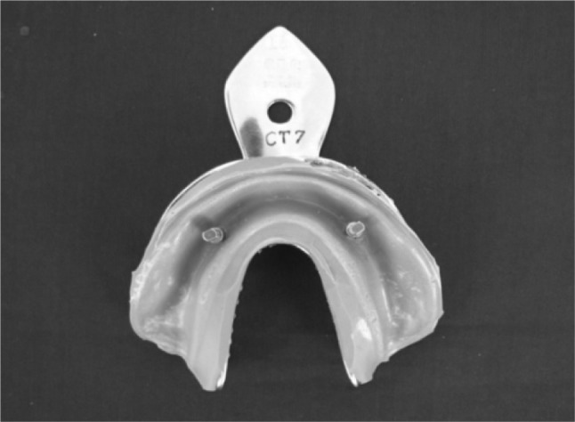
Closed tray impression
For open tray impressions (Fig. 2), custom trays were fabricated with light polymerising resin trays (Delta, India) and a spacer made of uniform thickness heat cure acrylic resin (Trevalon denture base material—Clear) template. The heat cure spacer with three tissue stops—one in the anterior midline and two in the either side molar regions was constructed of 4 wax sheets (Hindustan Modelling Wax) over the cast obtained from the impression of the master model and heat processed. After light polymerisation of trays the acrylic spacer was removed from the tray. This procedure was done for all 10 custom trays constructed. Thus the spacer with tissue stops ensure uniform thickness of putty impression material for all the impressions made. The open tray impression transfers were screwed into the implant fixtures in the master model using the hex driver. The impressions were made with double mix double take technique. Before making impression the modified needle cap (spacer for light body) was placed over the open tray transfers which prevented the adherence of putty material to the transfer coping. While making putty impression adequate pressure was applied so that all the three tissue stops were exposed. The modified needle cap spacer was removed from the impression, relief given using putty knife to create adequate space for light body. The light body material was loaded in the space occupied previously by the modified needle cap in the tray and around the open tray impression transfers in the model and the impression was made. The impressions were poured with type IV die stone. Casts were coded for the technique and the number of the impression. Totally 10 impressions were made for open tray technique and the casts were coded as OT-1, OT-2, OT-3, OT-4, OT-5 ,OT-6, OT-7, OT-8, OT-9, OT-10.
Fig. 2.
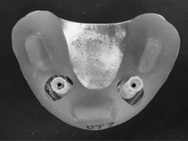
Impression tray for open tray technique and modified needle cap spacer for light body
Procedure for Analysis of Accuracy Using Strain Gage (Fig. 3)
Fig. 3.
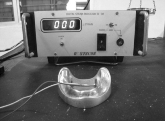
Master model with bar assembly connected to strain gage
The casts were analysed for accuracy comparing them with master model by screwing the bar (with torque wrench at 10 N cm) on each cast and attaching the electrical resistance strain gage (Digital strain indicator SI 30, SYSCON company) to the horizontal portion of the bar (Middle). The readings obtained were tabulated for each cast and were statistically analysed (Fig. 4).
Fig. 4.
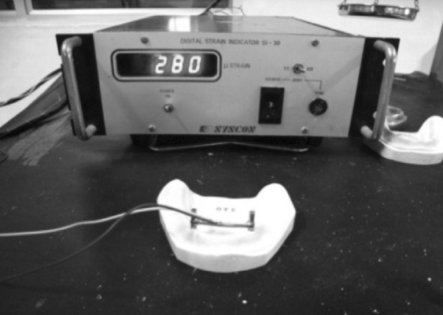
Bar with strain gauge fixed in open tray cast
Procedure for Analysis of Accuracy Using Coordinate Measuring Machine (Fig. 5)
Fig. 5.
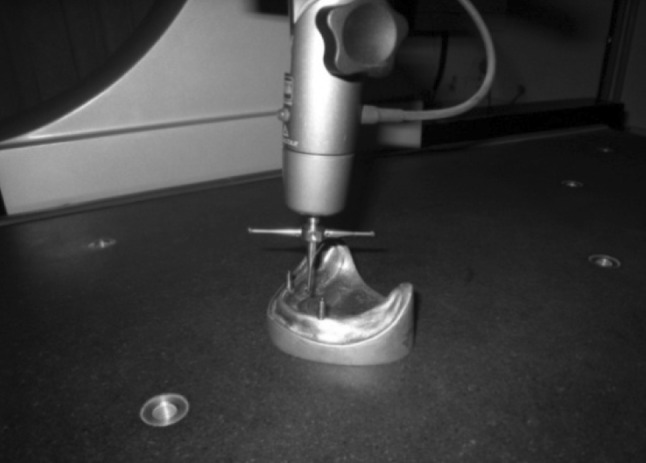
Measuring coordinates of the abutments fixed on the master model
The accuracy was also compared by measuring the change in the coordinates of the abutments with the coordinate measuring machine (C.M.M–TESA Microhite 3D, TESA Technologies). With this technique the standard abutments (MIS Dental Implant systems, Israel) for 3.75 mm dia internal hex implants was screwed into the master model implants with hex driver under finger pressure. This model was placed in the coordinate measuring machine and the coordinates of the abutments (screwed with torque of 10 N cm) were recorded from the central axis of them. Then the abutments were unscrewed and screwed with fixation screws (with torque of 10 N cm) on to the sample casts obtained with closed tray and open tray impression techniques. These casts were placed in the coordinate measuring machine and the x, y, coordinates and angularity of abutments were measured and recorded (Fig. 6). Then the difference in coordinates of the two abutments between the master model and the cast was calculated and tabulated for individual samples.
Fig. 6.
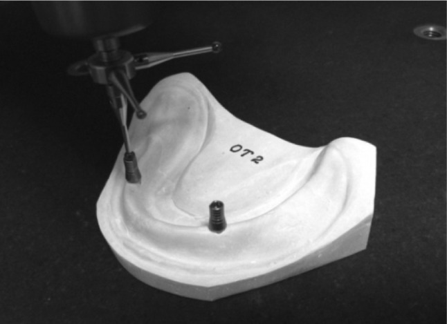
Measuring coordinates on the open tray cast
Results
The basic data of the results obtained in these investigations are presented in Tables 1, 2 and 3.
Table 1.
Strain gage values for sample casts
| Model codes closed tray technique (CT) | Strain values (microstrain) | Model codes open tray technique (OT) | Strain values (microstrain) |
|---|---|---|---|
| CT-1 | 518 | OT-1 | 182 |
| CT-2 | 275 | OT-2 | 98 |
| CT-3 | 308 | OT-3 | 210 |
| CT-4 | 276 | OT-4 | 85 |
| CT-5 | 285 | OT-5 | 280 |
| CT-6 | 386 | OT-6 | 126 |
| CT-7 | 439 | OT-7 | 148 |
| CT-8 | 379 | OT-8 | 133 |
| CT-9 | 282 | OT-9 | 120 |
| CT-10 | 440 | OT-10 | 133 |
Note: Master model strain value—0 μstrains
Table 2.
X, Y Coordinates and angularity of abutments at 35 and 45 positions of closed tray specimens
| Closed tray technique | |||||||||
|---|---|---|---|---|---|---|---|---|---|
| Y axis (mm) | Angle (°) | ||||||||
| X axis | Diff. | 35 | Diff. | 45 | Diff. | 35 | Radians | 45 | Radians |
| 26.791 | 0.422 | 8.657 | 0.458 | 8.875 | 0.09 | 4°33′27″ | 0.073798 | 4°13′42″ | 0.073798 |
| 26.782 | 0.431 | 8.601 | 0.514 | 8.77 | 0.195 | 5°51′12″ | 0.10216 | 5°15′48″ | 0.091862 |
| 26.696 | 0.517 | 8.624 | 0.491 | 8.74 | 0.225 | 4°49′01″ | 0.084072 | 4°13′42″ | 0.073798 |
| 26.688 | 0.525 | 8.683 | 0.432 | 7.79 | 1.175 | 4°36′31″ | 0.080435 | 4°13′39″ | 0.073784 |
| 26.634 | 0.579 | 8.579 | 0.536 | 8.874 | 0.091 | 4°10′47″ | 0.07295 | 4°14′11″ | 0.073939 |
| 26.756 | 0.457 | 8.695 | 0.42 | 8.76 | 0.205 | 4°45′41″ | 0.083102 | 4°13′40″ | 0.073789 |
| 26.799 | 0.414 | 8.759 | 0.356 | 8.81 | 0.155 | 6°22′45″ | 0.111337 | 5°16′54″ | 0.092182 |
| 26.769 | 0.444 | 8.698 | 0.417 | 8.77 | 0.195 | 6°29′18″ | 0.113243 | 4°13′41″ | 0.073793 |
| 26.673 | 0.54 | 8.524 | 0.591 | 8.74 | 0.225 | 6°47′40″ | 0.118585 | 5°15′28″ | 0.091766 |
| 26.714 | 0.499 | 8.723 | 0.392 | 7.8 | 1.165 | 4°26′41″ | 0.077575 | 4°13′42″ | 0.073798 |
| 27.213 | 9.115 | 8.965 | 4°51′16″ | 4°30′86″ | |||||
Values in bold at base of table—Master model values
º Degrees, ′ minutes, ′′ seconds
Table 3.
X, Y Coordinates and angularity of abutments at 35 and 45 positions of open tray specimens
| Open Tray Technique | |||||||||
|---|---|---|---|---|---|---|---|---|---|
| Y axis (mm) | Angle (°) | ||||||||
| X axis (mm) | Diff. | 35 | Diff. | 45 | Diff. | 35 | Radians | 45 | Radians |
| 27.112 | 0.101 | 9.112 | 0.003 | 8.91 | 0.055 | 4°45′12″ | 0.082961 | 4°11′58″ | 0.073296 |
| 27.088 | 0.125 | 9.01 | 0.105 | 8.544 | 0.421 | 4°38′40″ | 0.081061 | 4°10′53″ | 0.072981 |
| 26.983 | 0.23 | 9.028 | 0.087 | 8.6105 | 0.3545 | 4°55′30″ | 0.085957 | 4°21′9″ | 0.075967 |
| 27.201 | 0.012 | 9.218 | −0.103 | 8.677 | 0.288 | 4°40′32″ | 0.081604 | 4°13′2″ | 0.073602 |
| 27.003 | 0.21 | 9.303 | −0.188 | 8.943 | 0.022 | 4°56′37″ | 0.084537 | 5.5223″ | 0.074357 |
| 26.901 | 0.312 | 9.031 | 0.084 | 8.8765 | 0.0885 | 5°28′46″ | 0.095634 | 5°8′10″ | 0.089641 |
| 26.944 | 0.269 | 9.055 | 0.06 | 9.037 | −0.072 | 4°17′55″ | 0.075025 | 5.30″50″ | 0.069505 |
| 27.189 | 0.024 | 9.052 | 0.063 | 8.7435 | 0.2215 | 4°20′48″ | 0.075864 | 3°55′42″ | 0.068564 |
| 27.182 | 0.031 | 9.098 | 0.017 | 8.677 | 0.288 | 4°50′28″ | 0.084493 | 4°17′38″ | 0.074943 |
| 26.991 | 0.222 | 9.101 | 0.014 | 8.928 | 0.037 | 4°44′26″ | 0.082738 | 4°8′49″ | 0.072378 |
| 27.213 | 9.115 | 8.965 | 4°51′16″ | 4°30′86″ | |||||
Values in bold at base of table—Master model values
º Degrees, ′ minutes, ′′ seconds
Table 1 shows the values of strain gage obtained for 10 samples of each group after screwing the bar with attached strain gage. The mean of strain values for closed tray samples was 358.8 μstrains and for open tray samples was 151.5 μstrains. The open tray samples show the minimum strain value of the two groups compared.
Table 2 shows the values for the closed tray samples obtained with coordinate measuring machine. The x axis distance (in mm) between the center points of abutments at 35 and 45 positions and their differences from the master model values, y axis values (in mm) for abutments at 35 and 45 positions were tabulated separate and their difference from the master model values were denoted on their side columns. Same way the angularity of the abutments in 35 and 45 positions were tabulated in degrees and their corresponding radian values were also tabulated for the ease of statistical analysis.
Table 3 shows the values for the open tray samples obtained with coordinate measuring machine. The x axis distance (in mm) between the center points of abutments at 35 and 45 positions and their differences from the master model values, y axis values (in mm) for abutments at 35 and 45 positions were tabulated separate and their difference from the master model values were denoted on their side columns. Same way the angularity of the abutments in 35 and 45 positions are tabulated in degrees and their corresponding radian values were also tabulated for the ease of statistical analysis.
One way ANOVA analysis for X axis values of sample casts show that there was significant (2 tailed significance P < 0.001) difference between the close tray technique and open tray technique (F71.407). Mann–Whitney Test for Y axis values at 35, 45 position show that there was a significant (2 tailed significance P < 0.001) difference between the close tray technique and open tray technique. Mann–Whitney analysis for angularity values at 35 and 45 position show that there was significant (2 tailed significance P < 0.001) difference between the close tray technique and open tray technique. Mann–Whitney Test—for strain gage values show that there was significant (2 tailed significance P < 0.001) difference between the close tray technique and open tray technique.
Discussion
Many clinicians and authors [1, 2] have addressed the idea that passive fit of implant prostheses is essential for the long-term treatment success. The statistical correlation between prosthesis misfit and marginal bone level changes in maxillary implants with in vivo measurements has been examined [1, 3]. The human retrospective study by Assif et al. [4] found that prosthesis misfit is likely to increase the incidence of mechanical component loosening or fracture. This signifies the importance of the accuracy of the impression techniques and materials employed in implant supported restorations.
In the past though many studies were done comparing the closed tray indirect transfer/open tray direct transfer impression techniques [5, 6], stock closed tray versus custom open trays [7], Impression materials (Vinyl polysiloxane vs Polyether) [8] and splinted versus non splinted transfer techniques [2–4, 9] but not much literature is available comparing the direct transfer snapon impression coping closed tray impression technique and direct transfer open tray impression technique. The present study compares the direct transfer snapon impression coping closed tray impression technique and direct transfer open tray impression technique made with a single impression material (Vinyl polysiloxane). A single impression material was chosen for the study as the main attention was on the accuracy of transfer technique rather than the material accuracy. Vinyl polysiloxane was chosen as the material exhibits good resistance to permanent deformation, good flexibility and is most commonly used in day to day clinical practice.
The strain gage was attached to the cast bar in the middle of it and the output was connected to the strain gage which interprets the strain value in microstrain. The bar was cut and laser welded after fabrication for strain free fit in the master model as per the studies done by Riedy et al. [10]. Strain gage was selected for this study instead of other methods like travelling microscope [5, 7] or reflex microscope [3] because there is a component of operator error in the measurement with these instruments which is ruled out in the case of strain gage.
Similarly the use of coordinate measuring machine to measure three dimensional coordinates is superior to the reflex microscopes used in the previous study [3] in that the C.M.M automatically calculates the centroid point of the abutment and calculates the distance from that point unlike the reflex microscope which has to be done manually or from a point other than centroid.
The strain values of casts obtained with closed tray impression technique with snapon transfer copings show a wide, statistically significant diversion from the master model values. The mean of strain values for closed tray samples was 358.8 μstrains and for open tray samples was 151.5 μstrains. Hence the open tray samples show the minimum strain value of the two groups compared.
The mean value for x axis distance (in mm) in closed tray technique obtained casts was 26.73 mm and mean value for open tray casts was 27.05 mm. The mean value of open tray technique was closer to master model value of 27.21 mm. Hence the open tray technique had the least amount of distortion in x axis direction among the two techniques.
The mean value of y axis values (in mm) of abutment at 35 position for closed tray impression casts was 8.654 mm and mean value for open tray impression casts was 9.100 mm. The mean value of open tray technique was close to the master model value of 9.115 mm. The mean value of y axis values (in mm) of abutment at 45 position for closed tray impression casts was 8.592 mm and mean value for open tray impression casts was 8.79 mm. The mean value of open tray technique was close to the master model value of 8.965 mm. Hence the open tray technique had the least amount of distortion in y axis direction among the two techniques.
The mean value of angularity (in radians) of abutments in 35 position of closed tray technique casts was 0.09172 and that of open tray technique casts was 0.08298 which was close to the master model value of 0.08472 Similarly the mean value of angularity values (in radians) of abutments in 45 position for closed tray impression casts was 0.07925 and that of open tray technique casts was 0.07452 which was close to the master model value of 0.07520.
The results show a statistically significant variation (P < 0.001) among both the groups (techniques) and favor the open tray impression technique to be more accurate than closed tray technique (i.e., less distortion in the angularity with the open tray impression technique transfer compared to the closed tray impression transfer).
The results of the study are in accordance with the studies done by Carr [5], Burns et al. [7], Acka et al. [11] The inaccuracy is incorporated in the closed tray impression technique is consistent with the findings of Jorgenson [5] in that a permanent deformation was induced in an elastomeric impression material when recovering it from structures having undercuts 1.0 mm in height and depth. The transfer coping below the height of contour could easily provide such an undercut and lead to deformation. Improper alignment of the flat surface of closed tray impression post to the snap on impression coping, distortion and incomplete recovery of the vinyl polysiloxane impression material due to application of excess pressure in a direction opposite to that of flat surface while aligning them will lead to X axis and angularity variation.
The inaccuracy in y axis may be due to the improper seating of the closed tray transfer into the snapon impression coping to the full depth, or conversely excess pressure to seat which deforms the impression material with less than ideal elastic recovery. Wee [8] has reported that indirect impression copings do not return to their original position when replaced in vinyl poly siloxane impression. All these factors for error incorporation in the transfer process is eliminated with open tray impression technique. Also due to the less number of components involved in the transfer process the less the chance of error incorporation with the open tray impression technique. Further studies are required in this field with more number of implants and implants in various angulations to determine the versatility of the technique.
Conclusion
From the foregoing study for evaluating the accuracy of casts obtained from various implant impression techniques following conclusions have been drawn. The open tray impression technique for transfer of three dimensional implant position from master model to specimen casts using direct impression coping for open tray internal hex is more accurate than the closed tray impression technique using direct impression coping for closed tray internal hex. The open tray impression technique showed better accuracy than the closed tray technique on all the three parameters evaluated (x axis, y axis and angularity). This clinically implies that, more the number of components used for the impression procedure, more the chance for inaccuracy (error) getting incorporated. Hence a direct transfer impression technique with less number of components possible, ensures the high accuracy of transfer of implant positions from master cast to the laboratory cast which implies the accurate transfer of implant location from the patient to the laboratory cast.
Contributor Information
T. BalaMurugan, Phone: +91-98422-83938, Email: drbaluthangaraj@gmail.com
P. Manimaran, Email: manipulls@yahoo.com
References
- 1.Waskewicz GA, et al. Photoelastic analysis of stress distribution transmitted from a fixed prosthesis attached to osseointegrated implants . Int J Oral Maxillofac Implants. 1994;9(4):405–411. [Google Scholar]
- 2.Humphries RM, Bloem TJ. The accuracy of implant master casts fabricated for transfer impressions. Int J Oral Maxillofac Implants. 1990;5:331–336. [PubMed] [Google Scholar]
- 3.Herbst D, et al. Evaluation of impression accuracy for osseointegrated implant supported superstructures. J Prosthet Dent. 2000;83:555–561. doi: 10.1016/S0022-3913(00)70014-X. [DOI] [PubMed] [Google Scholar]
- 4.Assif D, et al. Accuracy of implant impression techniques. Int J Oral Maxillofac Implants. 1996;11(2):216–222. [PubMed] [Google Scholar]
- 5.Carr AB. A comparison of impression techniques for a five-implant mandibular model. Int J Oral Maxillofac Implants. 1991;6(4):448–455. [PubMed] [Google Scholar]
- 6.Conrad HJ, et al. Accuracy of two impression techniques with angulated implants. J Prosthet Dent. 2007;97:349–356. doi: 10.1016/S0022-3913(07)60023-7. [DOI] [PubMed] [Google Scholar]
- 7.Burns J, et al. Accuracy of open tray implant impressions: an in vitro comparison of stock versus custom trays. J Prosthet Dent. 2003;89:250–255. doi: 10.1067/mpr.2003.38. [DOI] [PubMed] [Google Scholar]
- 8.Wee AG. Comparison of impression materials for direct multi-implant impressions. J Prosthet Dent. 2000;83:323–331. doi: 10.1016/S0022-3913(00)70136-3. [DOI] [PubMed] [Google Scholar]
- 9.Vigolo P, Majzoub Z, Cordioli G. Evaluation of the accuracy of three techniques used for multiple implant abutment impressions. J Prosthet Dent. 2003;89:186–192. doi: 10.1067/mpr.2003.15. [DOI] [PubMed] [Google Scholar]
- 10.Riedy SJ, et al. Fit of implant frameworks fabricated by different techniques. J Prosthet Dent. 1997;78:596–604. doi: 10.1016/S0022-3913(97)70011-8. [DOI] [PubMed] [Google Scholar]
- 11.Akça K, Cehreli MC, et al. Accuracy of two impression techniques for ITI implants. Int J Oral Maxillofac Implants. 1999;14:885–888. [PubMed] [Google Scholar]


