

Abstract
This paper describes the use of a modified x,y-plotter to generate hydrophilic channels by printing a solution of hydrophobic polymer (poly(dimethyl siloxane; PDMS) dissolved in hexanes onto filter paper. The PDMS penetrates the depth of the paper, and forms a hydrophobic wall that aqueous solutions cannot cross. The minimum size of printed features is approximately 1 mm; this resolution is adequate for the rapid prototyping of hand-held, visually read, diagnostic assays (and other microfluidic systems) based on paper. After curing the printed PDMS, the paper-based devices can be bent or folded to generate three-dimensional (3D) systems of channels. Capillary action pulls aqueous samples into the paper channels. Colorimetric assays for the presence of glucose and protein are demonstrated in the printed devices; spots of Bromothymol Blue distinguished samples with slightly basic pH (6.5) from samples with slightly acidic pH (8.0). The work also describes using printed devices that can be loaded using multipipettes, and printed flexible, foldable channels in paper over areas larger than 100 cm2.
This paper describes the use of a modified desktop plotter to fabricate simple patterns of hydrophilic microchannels in paper. We defined the boundaries of the microchannels by printing a solution of poly(dimethyl siloxane) (PDMS) in hexanes onto filter paper, using an x,y-plotter as a print-engine. Because PDMS is an elastomer, the paper could be bent and folded, without destroying the integrity of the channels. The channels have a minimum width of 1 mm, and the minimum spacing between two channels can be as small as 1 mm. These dimensions are large relative to those normally encountered in microfluidic systems, but they are the right size for the basic analytical and diagnostic devices that are our primary objectives, since readout of these devices will often involve visual observations of unmagnified spots of analytes.1 We believe that this low-cost system for printing hydrophobic polymers and other materials on paper will be useful for prototyping simple paper-based diagnostics assays.
A variety of simple diagnostic tests (for example, “dip-stick” tests) rely on paper-based assays.2-15 Some of these tests analyze environmental conditions,16,17 or detect illness (often in the developing world).18-20 We have recently patterned paper into hydrophilic regions demarcated by hydrophobic walls using photolithography and conventional photoresists (SU-8; and poly(methyl methacrylate), or PMMA).1 The hydrophilic regions act as microfluidic channels, in which capillary action wicks aqueous samples into the device. This design provides the basis for diagnostic systems in paper that are more complex than the simplest dip-stick assays (in the sense that multiple assays can be performed on a small array with ~5–20 μL of blood, urine, or other fluid), but simpler and more affordable than higher-technology microfluidic assays.20-23
An advantage of using PDMS to pattern the paper rather than SU-8 or PMMA is that PDMS is an elastomer. Since PDMS in paper is significantly more flexible than is photoresist in paper, a paper device printed with PDMS can be folded without destroying the channel. Performing assays with creased systems of channels in paper allows parallel processing of samples with small volumes without requiring micropipettes or other tools to control the volume of the sample. We demonstrate one such device, which we call a “dip-star” assay, and which allows up to eight different colorimetric assays on a single sample having a volume between 5 and 20 μL.
This report describes a system for patterning channels on hydrophilic paper by using hydrophobic polymers to form the boundaries. Although this method still requires computer-aided design, and uses some reagents that are not readily available world-wide, it eliminates the need for a cleanroom and most expensive materials (including proprietary software) required for photolithography.24 By lowering the cost of design and prototyping, we intend this method to allow investigators without access to photolithographic equipment to explore paper-based microfluidics and diagnostics.
EXPERIMENTAL SECTION
Equipment and materials
We used a desktop plotter (Hewlett Packard 7550A) to pattern filter paper with a modified pen filled with an “ink” of PDMS diluted 3:1 (w/w) in hexanes. The plotter has several advantages over desktop printers: (i) The plotter can print on sheets of newsprint, (Whatman) filter paper, nitrocellulose, or many different materials. The area of the printed sheets can vary from <10 cm2 to over 500 cm2. (ii) The plotter does not fold or bend the sheets during the printing process; for this reason, the plotter is compatible with inks that do not dry immediately (e.g., PDMS, other polymers, or suspensions of particles) (iii) The plotter does not require proprietary software, and is available used for less than $US 50. The plotter can print on substrates attached to normal printer paper, or on substrates attached to a continuous feed. (iv) Instead of tamper-resistant printer cartridges, the plotter uses a series of up to eight pens, which are felt-tipped in normal printing, but which we modified to print the PDMS/hexanes solution. This design allows the plotter to use and choose among multiple types of ink during printing, and gives valuable versatility to the method. The shape of the pens ensures that the plotter recognizes each, and uses it properly.
Preparing the plotter
The plotter prints by holding a sheet of paper flat while a mechanical arm moves a pen over the paper. A separate motor moves the paper along an axis perpendicular to the motion of the mechanical arm. Since the mechanical arm recognizes the pens by their shape, we used replica molding of the original pens to fabricate alternative pens to hold the PDMS “ink” (Figure 1). We first generated PDMS casts of the original plotter pens (Figure 1A). We then removed the tapered tip of a glass pipette (5.5-mm inner diameter; 7.0-mm outer diameter) and placed the pipette at the center of each cast. We filled the remaining volume of the cast with polyurethane (NOA 61, Norland Optical Adhesives), or with PDMS, to form the body of the replacement pen. After curing under ultraviolet light, the polyurethane formed the body of the pen, while the pipette served as a reservoir.
Figure 1.


Schematic illustration of the fabrication process used to produce alternative pens for the plotter. The pens were used to print PDMS and other “inks” (A) On the left, an original, 4-cm long pen. On the right, an original pen embedded in PDMS (in blue). (B) Cutting the original pen from the PDMS mold leaves a void that can hold a glass pipet. (C) After filling the void with polyurethane and curing under ultraviolet light, the replica is nearly complete. Curing PDMS in the tip of the pipet forms a septum. Piercing the PDMS septum with a blunt 20G needle forms the tip of the pen. (D) Photograph of a replica-molded plotter pen.
We used a blunted 18G or 20G needle as the tip of the pen. A small amount of cured PDMS held the needle in place at the end of the pipette. The needle functions as the tip of the replacement pen, in analogy to the felt-tip of the original pen; the width of the needle controlled the amount of PDMS/hexanes solution dispensed by the pen, and therefore determined the width of the printed lines. The new pen fit in the mechanical arm of the plotter. We filled the pen with 3:1 PDMS:hexanes; the viscosity of this solution was approximately that of light syrup.
Defining hydrophilic channels in paper
Previous work revealed that several hydrophobic polymers—including SU-8 photoresist (Microchem), photocurable polyurethanes (Norland Optical Adhesives), and PDMS—can fully penetrate paper; after these polymers cured, an aqueous solution could only wet the hydrophilic areas in the paper, and no liquid wicked through the polymer “wall” that defined the channels.1 We used PDMS for printing in paper because a method based on the use of PDMS enables the use of commodity equipment without the need for a cleanroom, and because PDMS is so inexpensive. PDMS costs about 1/2 the price of polyurethane ($0.07/g vs $0.15/g), and costs 1/15 the price of SU-8 photoresist per gram ($0.07/g vs $1/g). PDMS cures after 1 hour at 70 °C, and does not require ultraviolet light to crosslink, as photoresist does. Printing requires less polymer to pattern a given area than does photolithography, because no development step is required to remove excess, unexposed photoresist. We patterned paper with other liquids (e.g., Teflon™ AF) and with less expensive materials (solutions of polystyrene, polypropylene, or polyisobutylene; see Supplemental Information) We favored printing with solutions of PDMS because (i) PDMS is a familiar material to investigators who work with microchannels, (ii) the replica molding to create the replacement pens required PDMS, and (iii) PDMS, when cured, is an elastomer, and allows us to explore manipulation of the paper device by bending and folding. Less expensive alternatives to PDMS (e.g., low molecular weight polypropylene, polystyrene, and polyisobutylene) may be preferable for specific applications. We estimate the price of the PDMS used as ink to pattern 100 cm2 of filter paper to be $0.01 to $0.02; 5-10 additional grams of PDMS is needed to make the pens. Other advantages of PDMS are that it is transparent, readily available, non-toxic, odorless, and easily diluted in hexanes or other organic solvents.25
Biochemical assays in printed channels
In an analogy to microfluidic systems in PDMS or glass, we designed a paper-based assay in which a sample enters an inlet channel before splitting into five equally sized channels leading to test zones. The inlet channel was open, meaning that no printed PDMS defined its edge; dipping the inlet into a liquid sample loaded the device (Figure 2). The five test channels were closed, and contained chemical indicators for three basic colorimetric assays: determining the pH of samples near pH 7 (~1 μL of 1 mM Bromothymol Blue in water, dried for 1 hour under ambient conditions), quantifying the concentration of glucose (1 μL of 0.6 M potassium iodide in water and 1 μL of 15 units/mL 1:5 horseradish peroxidase/glucose oxidase, dried for 1 hour under ambient conditions), and quantifying the concentration of proteins (1 μL 250 mM citrate buffer at pH 1.8 and 0.5 μL 3.3 tetrabromophenol blue in 95% ethanol, dried for 1 hour under ambient conditions).1 Supplemental Information shows the colorimetric quantification of concentrations of glucose and protein in samples.
Figure 2.

Forming hydrophilic channels in paper by printing hydrophobic PDMS. (A) A microfluidic system based on PDMS printed in filter paper. (B) A 10-μL sample of red ink wicks up the system of channels. (C) A simple assay for glucose (left) and protein (right) performed on a single 5-μL sample. The top channel indicates a neutral pH. The blue region in (C) is the region that shows a positive test for protein. The dashed lines indicate the edge of the paper. In all three cases, the bottom edge is not printed with PDMS.
To take advantage of the mechanical flexibility of paper patterned with PDMS (and, we presume, with other elastomers), we designed a new type of assay—which we call the “dip-star” assay (Figure 3)—with which we can perform more assays in parallel on a single sample than can the design described in Figure 2. The “dip-star” assay is also easier to load with a liquid sample, and requires less polymer to define the channels, than devices based on photoresist and a clover-leaf pattern.1 This device lacks an input channel; instead, the entire system is a closed asterisk shape. Folding the device in half twice yields a smaller square device, one corner of which was formerly the center of the asterisk. Dipping this corner into a liquid sample is therefore equivalent to dropping a volume of sample in the center of the unfolded device, but dipping requires no pipette or measuring device, and minimizes contact between the user and the sample. This device allowed up to eight assays instead of five with a small volume of sample, because the design required no space for an inlet channel.
Figure 3.
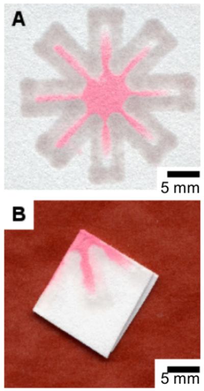
The dip-star design makes it possible to fold the channel system in the paper and dip it into a small volume of sample. (A) The unfolded printed paper after dipping. (B) The folded printed paper after dipping in 10 μL of red ink.
RESULTS AND DISCUSSION
Printing with “ink” of PDMS in hexanes
There were two major challenges to defining hydrophilic channels in paper by printing a hydrophobic polymer: first, the polymer must wet and penetrate the entire depth of the paper, so that a complete hydrophobic barrier forms to define the channels; second, the polymer must flow rapidly enough through the needle that makes up the distribution element in the pen (Figure 1) to serve as an “ink” in the automated printing device.
We determined the appropriate viscosity of the mixture of PDMS and hexanes for printing empirically by varying their proportions. We loaded the plotter with samples of various kinds of paper taped to normal printer paper, and filled the replacement pen with mixtures of various proportions of PDMS and hexanes (see Supplemental Information for the details of printing). The most consistent results occurred with PDMS:hexanes mixed in a 3:1 (w/w) ratio. Mixtures up to 4:1 PDMS:hexane also yielded sharp lines, but results were less consistent than with more dilute mixtures. Solutions with higher viscosity (i.e., with greater than 80% PDMS by weight) did not penetrate the paper; solutions with less than ~67% PDMS by weight led to ragged lines.
PDMS penetrated several kinds of paper completely; the types of paper included normal printer paper, filter paper, paper towels, and newsprint. After 1 hour at 70 °C, the PDMS cured to form a solid barrier across the complete thickness of the paper. Channels defined in filter paper wicked aqueous samples greater distances than did channels in other kinds of paper. Some broadening of features did occur while the printed polymer cured. The smallest resolved features in the paper were less than 1-mm wide (Figure 2A). For use in assays, we found that 2–4 mm wide channels were easy to fabricate and use. In these channels, 20 μL of an aqueous sample traveled over 1 cm to a five-way junction, and then split into five equal streams that each traveled at least 1 cm farther (Figure 2B).
To demonstrate the ability to print channels with a variety of designs over an area of ~100 cm2, we filled an area with the dip-star design (Figure 5A), and we printed a paper-based microfluidic device that can be loaded in parallel with six samples of 300 μL with a multi-pipette (Figure 5B).
Figure 5.
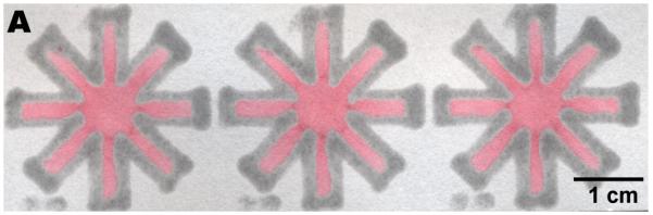
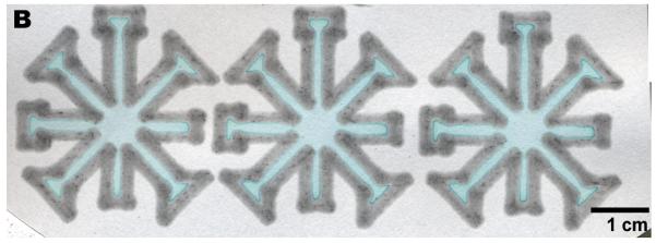

Printing over a large area. (A) Three dip-star assays. Carbon black was added to the PDMS “ink” and diluted ink was spotted at the center to improve visibility. The intensity of the red ink faded as the liquid flowed to the end of the channels, but the solvent always wicked through the entire device. (B) A slightly more complicated design that in (A). (C) A printed design that can be loaded by a multipipette.
Assays for protein, glucose, and pH
We used hydrophilic channels in paper defined by printing PDMS to make a simple parallel assay for glucose and protein (Figure 2C). These assays are well-known colorimetric assays that are used to detect excess of protein or glucose in urine. We applied ~1 μL of the reagents at the end of each channel, let the solutions evaporate, and then pipetted 20 μL of a solution of BSA and glucose at the inlet. We observed changes in color as soon as the solution reached the reagent the end of the channel. To analyze the pH of samples, we spotted the patterned filter paper with 1 μL of a 1 mM aqueous solution of Bromothymol blue (Sigma). In acidic conditions, Bromothymol blue becomes yellow, and in basic conditions it becomes blue. This indicator allowed us to distinguish among buffered samples near physiological values of pH, including slightly acidic pH (~6.5), neutral pH (~7) and slightly basic pH (~8).
We demonstrated all assays both in channels with the clover-leaf design (Figure 2) and the “dip-star” (Figure 4). We did not observe any cross contaminations between the different channels using these designs. Variation in the intensity of the colors produced by the assays for glucose and BSA allows a quantitative assay for these compounds (Supplemental Information, Figure 7). The intensity of the color of some types of ink faded noticeably as the liquid wicked down the channels, although the solvent reached the end of the channels (Figure 5A); we expect future work to exploit this effect, which we attribute to the chromatographic properties of the paper matrix.26
Figure 4.

Biochemical colorimetric assays using the “dip-star” design. (A) A protein assay (on the right), a glucose assay (on the left) before dipping the center of the folded printed paper in the sample. (B) The “dip-star” device after dipping it in an artificial urine solution containing glucose and BSA. The changes in color indicated the presence of both analytes. (C) The “dip-star” assay for pH before dipping the device into a sample. The right horizontal branch (boxed region) held the indicator. (D) The device after dipping it in a Tris buffer solution with pH 6.5. (E) The device after dipping it in a Tris buffer solution with pH 8.0.
CONCLUSIONS
Several properties make paper a potentially valuable material as a medium for storage of reagents, or as a platform for diagnostic assays: paper is inexpensive, light, biodegradable, familiar, and easy to modify chemically.25,27 This report demonstrates a fast, automated, highly reproducible technique for fabricating hydrophilic channels in paper over an area larger than 100 cm2 (Figure 5). The resolution of the printing is adequate for hand-held test-devices that are designed to be read by eye.
In principle, this method would also allow the use of many other “inks” in the plotter. We have used PDMS here because its solid-vapor interfacial free energy is low28 (γ = 21 erg/cm2) and allows it to wet the entire depth of the paper, and because it is flexible mechanically, inexpensive, non-toxic, and readily available. In addition to serving as an inexpensive platform for microfluidics, paper can also hold a crease and therefore can allow the fabrication of devices that would be impractical to create from microchannel systems made from PDMS29 or glass30. By relying on commodity tools and inexpensive materials for patterning, this method allows nearly any research laboratory to fabricate microfluidic systems in paper for diagnostics, assays, analysis, or other purposes.19,31
Supplementary Material
ACKNOWLEDGMENTS
This research was supported by NIH EHS grant GM065364, and DARPA (subaward to GMW from the Center for Optofluidic Integration at the California Institute of Technology). M.R. acknowledges the support of EMBO and HFSP in the form of a postdoctoral fellowship.
REFERENCES
- (1).Martinez A, Phillips S;, Butte M, Whitesides GM. Angew. Chem. Int. Ed. 2007;46:1318–1320. doi: 10.1002/anie.200603817. [DOI] [PMC free article] [PubMed] [Google Scholar]
- (2).Haeberle S, Zengerle R. Lab Chip. 2007;7:1094–1110. doi: 10.1039/b706364b. [DOI] [PubMed] [Google Scholar]
- (3).Behaj V, Cohen JI, Engel R. Anal. Lett. 2002;35:1715–1720. [Google Scholar]
- (4).Froom P, Etzion R, Barak M. Clin. Chem. 2004;50:673–675. doi: 10.1373/clinchem.2003.028589. [DOI] [PubMed] [Google Scholar]
- (5).Penders J, Fiers T, Delanghe JR. Clin. Chem. 2002;48:2236–2241. [PubMed] [Google Scholar]
- (6).Sasaki M, Pugia MJ, Parker DR, Kuromoto K, Furukawa I, Konishi I. J. Clin. Lab. Anal. 1999;13:246–250. doi: 10.1002/(SICI)1098-2825(1999)13:5<246::AID-JCLA10>3.0.CO;2-W. [DOI] [PMC free article] [PubMed] [Google Scholar]
- (7).Sharma A, Dour P, Sehgal RK. J. Food Safety. 2006;26:215–232. [Google Scholar]
- (8).Suzuki T. Methods. 2005;35:360–365. doi: 10.1016/j.ymeth.2004.10.008. [DOI] [PubMed] [Google Scholar]
- (9).Jin S, Chang ZY, Ming X, Min CL, Wei H, Sheng LY, Hong GX. Clin. Diagnost. Lab. Immunol. 2005;12:198–201. doi: 10.1128/CDLI.12.1.198-201.2005. [DOI] [PMC free article] [PubMed] [Google Scholar]
- (10).Metcalf EC, Morgan MRA, Dean PDG. J. Chromatog. 1982;235:501–506. [Google Scholar]
- (11).Paek SH, Lee SH, Cho JH, Kim YS. Methods. 2000;22:53–60. doi: 10.1006/meth.2000.1036. [DOI] [PubMed] [Google Scholar]
- (12).Tanaka R, Yuhi T, Nagatani N, Endo T, Kerman K, Takamura Y, Tamiya E. Anal. Bioanal. Chem. 2006;385:1414–1420. doi: 10.1007/s00216-006-0549-4. [DOI] [PubMed] [Google Scholar]
- (13).Zhang GP, Wang XN, Yang JF, Yang YY, Xing GX, Li QM, Zhao D, Chai SJ, Guo JQ. J. Immunol. Methods. 2006;312:27–33. doi: 10.1016/j.jim.2006.02.017. [DOI] [PubMed] [Google Scholar]
- (14).Zhu YC, He W, Liang YS, Xu M, Yu CX, Hua WQ, Chao GQ. J. Immunol. Methods. 2002;266:1–5. doi: 10.1016/s0022-1759(02)00086-8. [DOI] [PubMed] [Google Scholar]
- (15).Zlateva KT, Maes P, Rahman M, van Ranst M. Virol. J. 2005;2:6. doi: 10.1186/1743-422X-2-6. [DOI] [PMC free article] [PubMed] [Google Scholar]
- (16).Daar AS, Thorsteinsdottir H, Martin DK, Smith AC, Nast S, Singer PA. Nat. Genet. 2002;32:299–232. doi: 10.1038/ng1002-229. [DOI] [PubMed] [Google Scholar]
- (17).Illman DL. Anal. Chem. 2006;78:5266–5272. doi: 10.1021/ac0694324. [DOI] [PubMed] [Google Scholar]
- (18).Bell D, Wongsrichanalai C, Barnwell JW. Nat. Rev. Microbiol. 2006;4:682–695. doi: 10.1038/nrmicro1474. [DOI] [PubMed] [Google Scholar]
- (19).Mabey D, Peeling RW, Ustianowski A, Perkins MD. Nat. Rev. Microbio. 2004;2:231–240. doi: 10.1038/nrmicro841. [DOI] [PubMed] [Google Scholar]
- (20).Yager P, Edwards T, Fu E, Helton K, Nelson K, Tam MR, Weigl BH. Nature. 2006;442:412–418. doi: 10.1038/nature05064. [DOI] [PubMed] [Google Scholar]
- (21).Liu J, Hansen C, Quake SR. Anal. Chem. 2003;75:4718–4723. doi: 10.1021/ac0346407. [DOI] [PubMed] [Google Scholar]
- (22).Marcus JS, Anderson WF, Quake SR. Anal. Chem. 2006;78:956–958. doi: 10.1021/ac0513865. [DOI] [PubMed] [Google Scholar]
- (23).Sia SK, Linder V, Parviz BA, Siegel A, Whitesides GM. Angew. Chem. Int. Ed. 2004;43:498–502. doi: 10.1002/anie.200353016. [DOI] [PubMed] [Google Scholar]
- (24).Duffy DC, McDonald JC, Schueller OJA, Whitesides GM. Anal. Chem. 1998;70:4974–4984. doi: 10.1021/ac980656z. [DOI] [PubMed] [Google Scholar]
- (25).Lee JN, Park C, Whitesides GM. Anal. Chem. 2003;75:6544–6554. doi: 10.1021/ac0346712. [DOI] [PubMed] [Google Scholar]
- (26).Zweig G, Whitaker JR. Paper Chromatography and Electrophoresis. Academic Press; New York: 1971. [Google Scholar]
- (27).Zhu RH, Wang PL, Wang XF. Luminescence. 2005;20:382–388. doi: 10.1002/bio.848. [DOI] [PubMed] [Google Scholar]
- (28).Chaudhury MK, Whitesides GM. Langmuir. 1991;7:1013–1025. [Google Scholar]
- (29).Sia SK, Whitesides GM. Electrophoresis. 2003;24:3563–3576. doi: 10.1002/elps.200305584. [DOI] [PubMed] [Google Scholar]
- (30).Chen Q, Li G, Jin QH, Zhao JL, Ren QS, Xu YS. J. Microelectromech. Sys. 2007;16:1193–1200. [Google Scholar]
- (31).Chin CD, Linder V, Sia SK. Lab Chip. 2007;7:41–57. doi: 10.1039/b611455e. [DOI] [PubMed] [Google Scholar]
Associated Data
This section collects any data citations, data availability statements, or supplementary materials included in this article.