

Abstract
Rectifying electrical synapses are commonplace, but surprisingly little is known about how rectification alters the dynamics of neuronal networks. In this study, we use computational models to investigate how rectifying electrical synapses change the behavior of a small neuronal network that exhibits complex rhythmic output patterns. We begin with an electrically coupled circuit of three oscillatory neurons with different starting frequencies, and subsequently add two additional neurons and inhibitory chemical synapses. The five-cell model represents a pattern-generating neuronal network with two simultaneous rhythms competing for the recruitment of a hub neuron. We compare four different configurations of rectifying synapse placement and polarity, and we investigate how rectification changes the functional output of this network. Rectification can have a striking effect on the network's sensitivity to alterations of the strengths of the chemical synapses in the network. For some configurations, the rectification makes the circuit dynamics remarkably robust against changes in synaptic strength compared with the nonrectifying case. Based on our findings, we predict that modulation of rectifying electrical synapses could have functional consequences for the neuronal circuits that express them.
Introduction
The classical study demonstrating the electrical synapse in the crayfish escape circuit also showed that the connection was rectifying, that is positive current flows preferentially in one direction (Furshpan and Potter, 1959). Subsequently, the importance of electrical coupling in both invertebrate and vertebrate nervous systems has become evident (White et al., 1986; Rela and Szczupak, 2004; Pereda et al., 2013; Sasaki et al., 2013). Electrical synapses are often thought to promote speed and synchrony in excitable tissues, such as the heart and in the nervous system. Although network synchronization often results from electrical coupling (Chow and Kopell, 2000; Lewis and Rinzel, 2000; Pfeuty et al., 2003), gap junctions can have the opposite effect by desynchronizing network neurons. For example, electrical coupling between Golgi neurons produces surround inhibition when neurons receive sparse excitatory inputs (Vervaeke et al., 2010). Furthermore, electrical synapses create complex input–output functions in combination with chemical synapses (Spira et al., 1976; Kopell and Ermentrout, 2004; Rela and Szczupak, 2004).
The present study aims to further our understanding of electrical synapses by exploring their rectification in a neuronal circuit model. A single cell can express multiple gap-junction monomers, thus forming a diverse set of gap junction hemi-channels (Dermietzel, 1998). Rectifying gap junctions are thought to result from the joining of two different gap junction hemi-channels (Phelan et al., 2008).
Because junctions are known to be rectifying only when electrophysiological, intracellular recordings have been made (Devor and Yarom, 2002), the prevalence of rectification is likely to be underestimated. Specifically, when electrical synapses are identified on the basis of gap junctions seen in the electron microscope (White et al., 1986), it is unknown whether they support current flow equally in both directions or rectify. Nonetheless, in many preparations in which appropriate recordings have been made, rectifying electrical synapses have been shown to support specialized functions (Marder, 1998; Rela and Szczupak, 2004). Motor neurons in the midbody ganglion of the leech rely on rectifying gap junctions as a crucial part of a negative feedback loop built into the circuit (Rela and Szczupak, 2003). The circuit has the capacity to regulate the motor neurons in a state-dependent manner due to this circuit feature (Rela and Szczupak, 2004). The crayfish escape reflex depends on coincidence detection that results from rectifying electrical synapses. As a result of multiple inputs either summing or interfering, coincidence detection is an unavoidable feature endowed upon neurons that receive multiple rectifying electrical synapses of the same polarity (Edwards et al., 1998).
The prevalence of rectifying electrical synapses makes it important to understand the role of rectification in the circuits in which these junctions are found. To that end, we investigate how rectification affects the functional output of a 5-cell, pattern-generating, model circuit and its sensitivity to synaptic modulation.
Materials and Methods
Model networks.
Cells were modeled as Morris–Lecar (Morris and Lecar, 1981), single-compartment neurons modified by a hyperpolarization-activated current as in our previous study (Gutierrez et al., 2013). Each cell's membrane voltage, Vm, was computed by solving the membrane equation:
 |
Cm is the membrane capacitance and is equal to 1 nF for all neurons. Reversal potentials for the various currents are Vleak = −40 mV, Vca = 100 mV, Vk = −80 mV, Vh = −20 mV, Vsyn = −75 mV. The hyperpolarization-activated current is based on equations and parameters that were modified from (Turrigiano et al., 1995). The remaining ionic currents are based on equations modified from (Skinner et al., 1993).
 |
where v1 = 0 mV and v2 = 20 mV.
 |
where v3 = 0 mV and v4 = 15 mV.
 |
where v5 = 78.3 mV, v6 = 10.5 mV, v7 = −42.2 mV, v8 = 87.3 mV.
M∞, N∞, and H∞ are steady-state gating variables for the calcium, potassium, and hyperpolarization-activated currents, respectively. N and H are time-dependent gating variables for the potassium and hyperpolarization-activated currents, respectively. The gating variable, N, is modified by λN, a hyperbolic, U-shaped curve whose nadir height and eccentricity are determined by ϕN which equals 0.002 ms−1. The variable τh is the voltage-dependent recovery time constant. It controls the rate of change of H so that H changes less steeply for more depolarized voltages.
All synapses were modeled as instantaneous. Electrical synapses were either rectifying or nonrectifying. The electrical conductance, gel, determined the strength of the electrical synapses. Electrical coupling conductances ranged from 0 nS to as much as 9.5 nS.
 |
for a rectifying synapse that permits negative current to flow from Vm1 to Vm2.
The rectification function, Grec∞, is an approximation of the experimental rectification data in Phelan et al. (2008). Gmax = 1, vα = 8 mV, and Gmin = 0 (Fig. 1A). For nonrectifying synapses, Grec∞ was a constant equal to 1.
Figure 1.

A rectifying gap junction between an intrinsic oscillator and a leaky oscillator. A, Rectification is a function of the difference in voltage between two electrically coupled cells. The rectification of the electrical synapses in this study is modeled by this Grec∞ sigmoid which controls the amount of electrical coupling conductance as a function of voltage difference. B, The voltage traces of an intrinsically oscillating neuron (green) and a leaky, conditionally oscillating neuron (pale blue) show their intrinsic activity when they are not coupled. In C they are coupled by a rectifying gap junction (diode symbol) that readily permits negative (hyperpolarizing) current to pass from the oscillator to the leaky cell while restricting the flow of negative current in the opposite direction. Naturally, positive current is able to pass from the leaky neuron into the oscillator; however, its passage into the leaky neuron from the oscillator is restricted. The voltage traces show their resulting activity. D, The polarity of the rectifying gap junction is reversed so that positive current can easily pass from the oscillator to the leaky neuron and negative current can just as easily pass from the leaky neuron to the oscillator. The inverse current flow, however, is restricted.
Chemical inhibitory synapses were modeled by equations modified from Prinz et al. (2004). S∞ is the steady-state synaptic current gating variable and was modeled after the graded synaptic transmission seen in crustacean stomatogastric neurons (Manor et al., 1997). We used inhibitory synaptic conductance strengths (gsynHC and gsyn1) ranging from 0 nS to 10 nS. Each of the two synapses that form a half-center coupling have the conductance value denoted by gsynHC.
 |
where vβ = 5 mV and vth = −25 mV.
All model neurons in this study are endogenous oscillators and the maximal conductances for the different neurons were chosen to achieve the intrinsic oscillation frequencies required. Conductances for the neurons in the five-cell circuit were as follows [fast; f1,f2: gca = 1.9 × 10⁻² μS, gk = 3.9 × 10⁻² μS, gh = 2.5 × 10⁻² μS; hub neuron(intermediate); hn: gca = 1.7 × 10⁻² μS, gk = 1.9 × 10⁻² μS, gh = 8.0 × 10⁻³ μS; slow; s1,s2: gca = 8.5 × 10⁻³ μS, gk = 1.5 × 10⁻² μS, gh = 1.0 × 10⁻² μS; all gleak = 1 × 10⁻⁴ μS]. The neurons in Figure 1 have the same ionic conductances as hn except for gleak which is 1 × 10⁻³ μS and 1 × 10⁻² μS for the oscillator and leaky neuron respectively. The neurons in the three-cell circuit in Figure 2 have the following conductances [f: gca = 2.0 × 10⁻² μS, gk = 4.0 × 10⁻² μS, gh = 1.9 × 10⁻² μS; m: gca = 1.7 × 10⁻² μS, gk = 2.0 × 10⁻² μS, gh = 9.0 × 10⁻³ μS; s: gca = 1.48 × 10⁻² μS, gk = 2.5 × 10⁻² μS, gh = 4.0 × 10⁻⁴ μS; all gleak = 1 × 10⁻⁴ μS].
Figure 2.

Synchronization properties of three heterogeneous, electrically coupled neurons. An intrinsically fast (red), medium (green), and slow (blue) oscillator (the dashed lines plotted are their respective isolated frequencies) are serially, electrically coupled with nonrectifying (Case 0) electrical synapses. Case 1, A rectifying synapse between the f and m neurons that restricts negative current from the f to the m neuron and a nonrectifying synapse between the m and s neurons. Case 2, A rectifying synapse between the f and m neurons that restricts negative current from the m to the f neuron and a nonrectifying synapse between the m and s neurons. Case 3, a rectifying synapse between the m and s neurons that restricts negative current from the s to the m neuron and a nonrectifying synapse between the m and f neurons. Case 4, a rectifying synapse between the m and s neurons that restricts negative current from the m to the s neuron and a nonrectifying synapse between the m and f neurons. Neuron oscillation frequencies are plotted as a function of electrical synapse conductance in nanosiemens (nS). Both synapses in the circuit are varied together along the x-axis. Resistor symbols are nonrectifying electrical synapses and diode symbols are rectifying electrical synapses.
Simulations and analysis.
All data and figures presented in this paper are from simulations performed in MATLAB using the variable time-step solver ode45 function (fourth/fifth order Runge–Kutta integration). Simulations produced 655 s long voltage waveforms for each of the five neurons. The first 55 s were eliminated from analysis. MATLAB scripts were made to compute the oscillation frequencies from the truncated 600 s lengths of data. The threshold for a membrane depolarization to be considered a spike was set at 0 mV and frequency was calculated to be the inverse of the mean spike period over the 600 s interval. Network parameterscapes were done in MATLAB as described in Gutierrez et al. (2013). Code available on request.
Results
Many computational studies of the effects of gap junctions in networks assume that all of the component neurons are identical and have not investigated the effects of rectification. In contrast, in biological systems, many electrical synapses are between neurons of different cell types, and may be rectifying. Therefore, we focus on the effects of rectifying junctions between neurons with different intrinsic membrane properties. We begin with an example of two electrically coupled neurons because it offers some insights into the findings that follow when we look at a chain of three heterogeneous oscillators. The three-cell chain then forms the kernel of the five-cell pattern-generating circuit that we use to explore the dynamics that result from rectification in a network with both electrical and chemical synapses.
Rectification between two heterogeneous neurons
The effect of a rectifying electrical synapse between an intrinsically oscillating neuron and a leaky neuron is shown in Figure 1. Uncoupled, the oscillator's membrane potential fluctuates between depolarized and hyperpolarized voltages, whereas the leaky neuron's membrane potential is steady at around the leak reversal potential (Fig. 1B). With a rectifying electrical synapse that restricts the flow of negative current from the leaky neuron to the intrinsic oscillator, whereas positive current flow is restricted in the opposite direction, the leaky neuron is hyperpolarized during the trough of the oscillator's waveform and the intrinsic oscillator's frequency is slightly increased (Fig. 1C). Reversing the polarity of the rectifying electrical synapse restricts negative current flowing from the intrinsic oscillator to the leaky neuron. With this configuration, both neurons oscillate synchronously (Fig. 1D). Although in Figure 1C the leaky neuron only really hyperpolarizes relative to its baseline, in Figure 1D the leaky neuron both depolarizes and hyperpolarizes relative to its baseline. The negative deflections in the leaky neuron's membrane potential in Figure 1D are due to the activation of its intrinsic hyperpolarizing membrane currents as a result of its depolarization through the rectifying gap junction. Figure 1 illustrates that, depending on the direction of rectification, the oscillatory neuron can either produce a net rhythmic hyperpolarization or a net rhythmic depolarization to the leaky coupled neuron. More importantly, the intrinsic properties of the neurons determine how the rectifying electrical synapse will affect their activity as demonstrated by Figure 1D. Although this is to be expected for this pair, it is important to bear in mind for the larger circuits we study subsequently.
The current flow and its rectification are a function of the voltage difference between the coupled neurons (Fig. 1A). Take for example the rectifying synapse in Figure 1C; when the oscillator is more hyperpolarized than the leaky neuron, Vleaky− Voscillator is positive and Grec∞ is between 0.5 and 1 meaning that current flow through the gap junction is facilitated. When the oscillator is more depolarized than the leaky neuron, Vleaky− Voscillator is negative and Grec∞ is between 0 and 0.5 which means that current flow through the gap junction is restricted. Note how the more depolarized the oscillator is than the leaky neuron, the more current flow is restricted. For the rectifying gap junction of the reverse polarity in Figure 1D, the Grec∞ sigmoid is reflected about the axis where V1−V2 = 0.
Rectification in a three-cell chain of heterogeneous neurons
We next look at the effects of rectification on a three-cell circuit that demonstrates that the effect that a rectifying electrical synapse has on circuit synchronization depends on the polarity of the synapse and the intrinsic properties of the neurons on either side of it.
In isolation, each of the three neurons in Figure 2 is an oscillator, but their frequencies are different. If the neurons are serially coupled with nonrectifying electrical synapses, they oscillate synchronously near the mean of their isolated frequencies given enough electrical coupling conductance (Fig. 2, Case 0). In this case, the slow (s) and the medium (m) frequency neurons synchronize at a slightly lower value of the coupling conductance than that required before all three synchronize. Replacing the electrical synapse between the intrinsically fast (f) and medium-frequency neurons with a rectifying electrical synapse that restricts negative current from the fast to the medium neuron (and restricts positive current in the opposite direction) yields similar results, but shifts the coupling conductance needed to synchronize the three neurons to a slightly higher value (Fig. 2, Case 1). However, a rectifying synapse of the opposite polarity between the fast and medium neurons results in a circuit that requires a much higher coupling conductance before all three neurons synchronize (Fig. 2, Case 2).
The contrast between these two cases has an intuitive explanation. Because in isolation the fast neuron oscillates at a higher frequency than the other two neurons, the hyperpolarizing current it receives from the medium neuron when they are coupled with the rectifying synapse in Case 1 allows it to lower its oscillation frequency to meet the other neurons. When the polarity of the rectifying synapse is reversed, the fast neuron's source of hyperpolarizing synaptic current is restricted, whereas the depolarizing current it receives pushes its frequency further away from that of the other neurons until a high enough coupling conductance can synchronize them. As coupling conductance is increased, the fast neuron is able to receive more negative synaptic current when the junctional potential is near zero. Similarly, Cases 3 and 4 (Fig. 2) show how the polarity of a rectifying synapse can work for, or against, the intrinsic properties of the neurons flanking it and this can have consequences for circuit output. In Case 3, restricting positive current to the slow neuron makes it difficult for it to synchronize with the other faster neurons. However, in Case 4, the slow neuron is able to synchronize with the other neurons at a lower coupling conductance despite having negative current flow into the slow neuron restricted. The rectifying electrical synapses in Cases 1 and 4 cooperate with the neuron intrinsic properties because the sign of the permitted current flow through the synapse facilitates synchrony among the coupled neurons. Hyperpolarizing current flows easily from m to f in Case 1, whereas in Case 4 depolarizing current flows easily from m to s, allowing f to decrease its frequency and s to increase its frequency to meet the other neurons in the respective cases. Conversely, in Cases 2 and 3 the relationship is antagonistic because the asymmetrical current flow through the rectifying electrical synapse results in the coupled neurons diverging in frequency. More explicitly, in Case 2 depolarizing current flows easily from m to f causing the frequency of f to increase away from the other neurons. In Case 3, because hyperpolarizing current flows more easily from m to s, the slow neuron's frequency is suppressed making it difficult for s to synchronize with the other neurons.
Consequences of rectification for a pattern-generating circuit
In the three-cell circuit, we saw the effects of rectification on synchronization among cells of disparate frequencies. Now, we look at the effects of rectification in a circuit that can generate a variety of different output patterns, such as in the central pattern generating circuits seen in invertebrates (Marder and Calabrese, 1996; Marder and Bucher, 2007). As an example, we study the effects of rectification on a five-cell circuit that is loosely motivated by the connectivity in the crab stomatogastric ganglion (Gutierrez et al., 2013). In this circuit there are two intrinsically fast neurons (f1 and f2) that mutually inhibit each other, two intrinsically slow neurons (s1 and s2) that mutually inhibit each other, and an intermediate-frequency hub neuron (hn) that is electrically coupled to one of the fast and one of the slow oscillators (Fig. 3A).
Figure 3.

Pattern-generating five-cell circuit. A, The electrically coupled three-cell circuit motif becomes the core of the five-cell circuit. B, The intrinsically fast neuron is mutually inhibited by another intrinsically fast neuron forming a half-center oscillator, and likewise for the slow neuron (gsynHC = 5 nS). Without electrical coupling, the hub neuron (hn) between these two pattern-generating components intrinsically oscillates at a frequency intermediate to the half-center frequencies of the fast and slow pair. C, When hn is electrically coupled to f2 and s2 with gel equal to 3 nS, the circuit outputs a stable rhythmic pattern and hn oscillates at the frequency of the fast half-center. Scale bars, 100 mV and 2 s.
Both mutually inhibitory pairs (coupled with synaptic strength gsynHC) form half-center oscillators as seen in the traces in Figure 3B. This endows the circuit with pattern-generating capabilities such that the mutually inhibitory pairs set up two distinct rhythmic patterns. In the half-center oscillator formed by the two fast neurons, f1 and f2 take turns “firing” in alternation. The slow neurons also form a half-center oscillator but at a lower frequency than the fast half-center. The hub neuron, hn, between the rhythm-generating parts of the circuit intrinsically oscillates at a frequency intermediate to the fast and slow half-center frequencies (Fig. 3B). In contrast to the three-cell circuit, hn is flanked by two half-center subcircuits of different frequencies in this five-cell circuit, rather than by two neurons with differing frequencies. The electrically coupled neurons on either side of hn now have the additional pull of their mutually inhibiting partners to compete with the influence of the electrical coupling.
The fast and slow rhythms can be coordinated by hn via the electrical coupling (Fig. 3C). When hn is electrically coupled to one neuron in each half-center oscillator (f2 and s2), it can coordinate the two sides of the circuit such that the fast and slow half-centers fire in a stable 2:1 frequency relationship with each other. In the example in Figure 3C, hn joins the fast half-center oscillator's frequency.
In this five-cell circuit, electrical coupling competes with the half-center coupling (i.e., the mutually inhibitory chemical synapses) to determine the electrically coupled cells' activity. With low half-center inhibitory coupling conductance, the electrically coupled neurons (f2, hn, and s2) synchronize at the same frequency while the nonelectrically coupled neurons (f1 and s1) oscillate close to their intrinsic frequencies (Fig. 4A). However, the effect of these synaptic parameters is not limited to the activity of the electrically coupled neurons, but extends to the nonelectrically coupled ones as well. This is seen in Figure 4B in which, as a result of increasing both electrical and half-center coupling strength, the nonelectrically coupled intrinsically fast neuron (f1) has joined the electrically coupled neurons at the same frequency leaving only the nonelectrically coupled, intrinsically slow neuron (s1) to oscillate near its intrinsic frequency. Naturally, high half-center coupling conductance will make it less likely for the neurons on either side of the hub neuron to be pulled out of synchrony with their mutually inhibiting partners, so hn will join one of the half-center oscillators. In Figure 4C, the half-centers (f1, f2, and s1, s2) oscillate near their intrinsic frequencies, whereas hn is captured by the fast oscillators. When both half-center coupling and electrical coupling are high, the network finds a stable compromise between the opposing forces such that half-center relationships are preserved while the three electrically coupled neurons synchronize. For example, in Figure 4D, all neurons oscillate at a common frequency, but alternation between f1 and f2, and between s1 and s2 is maintained.
Figure 4.
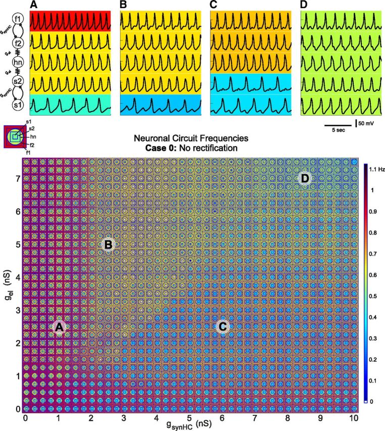
Circuit output as a function of gsynHC and gel. A–D, Voltage traces show the activity of the circuit with nonrectifying electrical synapses for various conductance strength combinations. A, gsynHC = 1 nS, gel = 2.5 nS; (B) gsynHC = 2.5 nS, gel = 5 nS, (C) gsynHC = 6 nS, gel = 2.5 nS; and (D) gsynHC = 8.5 nS, gel = 7 nS. Background colors indicate neuron oscillation frequency. Parameterscape (below) shows circuit activity for a range of electrical (gel) and half-center coupling (gsynHC) conductance combinations with overlapping concentric shapes at each point. Key (above left of parameterscape) shows which neuron corresponds to each concentric shape. Colors represent suprathreshold voltage oscillation frequency (color axis) in hertz with blue shades indicating low frequencies and red shades indicating high frequencies.
The addition of the half-center coupling parameter requires a plotting method to accommodate this added dimension when probing a range of synaptic conductances. We recently developed a method called the “parameterscape” that allows the visualization of any network attribute (in this case the frequencies of the five circuit neurons) as a function of two network parameters (Gutierrez et al., 2013). Each point on the parameterscape shows the activity of all five neurons with a series of concentric shapes that are color-coded for oscillation frequency (Fig. 4, parameterscape key). At each point, the circuit activity for a particular set of synaptic conductances can be ascertained at a glance. The patterns of network activity shown in the traces of Figure 4 can be seen at the points labeled A–D in the parameterscape below the traces. The electrically coupled neurons (f2, hn, and s2) synchronize whenever gel is greater than gsynHC (and >1.5 nS), but this relationship is not linear.
We hypothesized that the network output patterns generated by this five-cell circuit would be changed by making any of the electrical synapses rectifying. So we generated parameterscapes for four cases of rectification. The rectification configurations from Figure 2 are used for the three electrically coupled neurons within the five-cell circuit. Recall that in Case 1, the electrical coupling between f2 and hn is rectifying so that negative current flows freely from hn to f2. The polarity of this rectifying synapse between f2 and hn is reversed in Case 2. Case 3 has a rectifying electrical synapse between s2 and hn such that negative current flows freely from hn to s2 and Case 4 has the opposite polarity synapse. Indeed, the effect of rectification on network output in the five-cell circuit echoes that in the three-cell circuit. For Cases 1 and 4 where the rectifying electrical synapses cooperate with the intrinsic properties of the neurons, the parameterscapes (data not shown) looked similar to the parameterscape in Figure 4 in which none of the synapses are rectifying. However, for Cases 2 and 3 in which the rectifying electrical synapses have an antagonistic relationship with the neurons' intrinsic properties, the parameterscapes were drastically changed from that seen in Figure 4. The parameterscape for Case 2 (Fig. 5, top) is dominated by network behavior in which hn oscillates with the intrinsically slow half-center pair leaving the intrinsically fast half-center oscillator active at a higher frequency. However, in Case 3 (Fig. 5, bottom) hn oscillates with the intrinsically fast half-center oscillators for most of the synaptic conductance strengths in the parameterscape. In each of these two cases, the rectifying electrical synapse effectively gates off one of the rhythm-generating parts of the circuit leaving it to be active on its own, whereas the nonrectifying synapse facilitates synchrony between hn and the other half-center pair. This effective “gating-off” leads to robustness of one network pattern within the parameterscape and makes other network patterns “forbidden,” at least in the synaptic conductance ranges studied (simulations were run for gel values up to 9.5 nS, but as conclusions were not affected by the extended range, only values up to 7.5 nS are plotted here).
Figure 5.
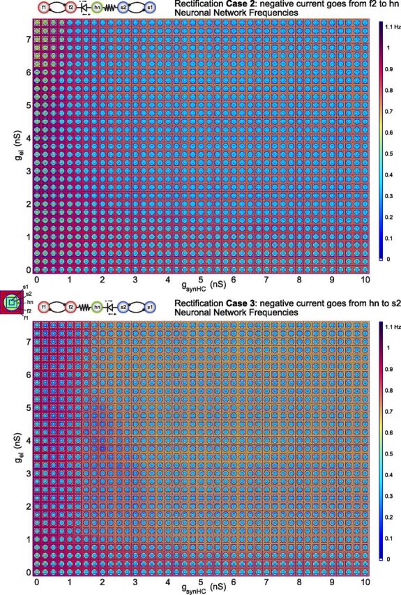
Circuit output with rectification. Parameterscapes of neuron frequencies for Case 2 rectification (top) and Case 3 rectification (bottom) in the five-cell circuit. The half-center coupling conductance is varied along the x-axis (gsynHC), while electrical coupling conductance is varied along the y-axis (gel) as in the parameterscape in Figure 4.
An intuition about the gating-off effect discussed above can be gained from the three-cell circuit in Figure 2. In fact, by choosing a single half-center conductance value and focusing on a column of a parameterscape in Figure 5, the frequencies of the electrically coupled neurons as gel is increased follow a similar pattern in the five-cell circuit as in the three-cell circuit. The only difference is that a point at which all three electrically coupled neurons in the five-cell circuit synchronize is never reached in Cases 2 and 3 of Figure 5.
Rectification and parallel pathways
Many neuronal circuits have parallel pathways between neurons that impact the complexity and robustness of the circuit. In this context, parallel pathways enable one neuron to communicate with another neuron via multiple routes, and can include both monosynaptic and polysynaptic connections. Parallel pathways can permit the nature of the communication to differ depending on modulatory state. For example, a neuron that sends both an inhibitory chemical synapse and an electrical synapse to its postsynaptic partner can have either a desynchronizing or synchronizing effect depending on the strengths of these synapses (Lewis and Rinzel, 2003; Bem and Rinzel, 2004). An intuition about the gating-off effect in Figure 5 was gained from studying the three-cell circuit, but how might this gating be affected if there are parallel pathways through which the hub neuron can be dually influenced by the pattern-generating components of the circuit? To address this question, we added inhibitory synapses from the nonelectrically coupled neurons to hn. The behavior of this particular circuit with only nonrectifying synapses was studied in detail in Gutierrez et al. (2013). Here, we focus on the impact of rectification on this circuit and develop a comparison between the network outputs in Cases 2 and 3 with and without parallel pathways.
The conductances of the synapses that form the half-centers were set to a constant value of 5 nS, whereas the conductances of the inhibitory synapses onto hn were varied, as well as the electrical coupling conductances. In the parameterscapes in Figure 6, the conductances of the inhibitory synapses that project to hn (gsyn1) are varied along the x-axis.
Figure 6.
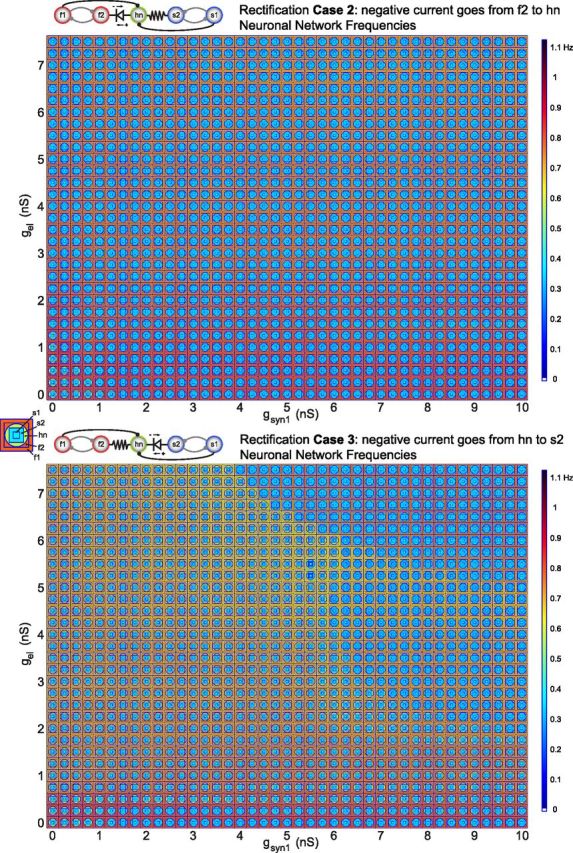
Circuit output with rectification and parallel pathways. Parameterscapes of neuron frequencies for Case 2 rectification (top) and Case 3 rectification (bottom) in the five-cell circuit with parallel pathways to hn. Half-center coupling (gsynHC) is kept constant at 5 nS throughout the parameterscapes. The conductances of the inhibitory synapses from s1 and f1 onto hn are varied along the x-axis (gsyn1), whereas electrical coupling conductance is varied along the y-axis (gel).
In relating the parameterscapes in Figure 5 to those in Figure 6, it is helpful to note that the first columns of the parameterscapes in Figure 6 correspond to the middle columns in the parameterscapes in Figure 5, where gsynHC is 5 nS. Modulation of only gel and gsyn1 results in homogenous network behavior in Case 2 (Fig. 6, top). That means that the network only produces one pattern for this range of synaptic conductances. Regardless of whether gsyn1 is much higher or lower than gel, hn is always active with the slow rhythm except when both gsyn1 and gel are very low (<1 nS). The striking homogeneity of this parameterscape reveals this network's insensitivity to the modulation of not only electrical synapse conductance but also the modulation of the inhibitory synapses impinging onto hn.
In Case 3, the parallel pathways have the inverse effect by expanding the repertoire of circuit behaviors (Fig. 6, bottom). In other words, the circuit for Case 3 in Figure 6 displays more than one output pattern as a function of the electrical and parallel inhibitory synapse strengths in contrast to Case 2 and, more importantly, in contrast to Case 3 in Figure 5. The inhibitory synapse from s1 to hn, in effect, compensates for the rectification of the electrical synapse between s2 and hn because it provides some of the slow, rhythmic hyperpolarization that the rectifying electrical synapse restricts. Thus, hn can be recruited into the slow rhythm for high enough gsyn1 values despite the antagonistic relationship between the rectifying electrical synapse and the neurons' intrinsic properties. Furthermore, at the highest values of gsyn1 and gel (Fig. 6, bottom; top right part of the plot), f2 can also be recruited into the slow rhythm leaving f1 to oscillate at a higher frequency alone. Despite their disparate frequencies, f1 and f2 maintain their half-center relationship by oscillating in a 2:1 frequency pattern. For the lower range of gsyn1 values, the circuit displays the same robust pattern that dominated the parameterscape in Case 3 of Figure 5. In Case 3 of Figure 6, however, the parallel pathway behaves like a switch that determines whether or not modulation of electrical synapse conductance will be able to modify the circuit pattern. When gsyn1 is low, the circuit is robust against modulation of gel but when gsyn1 is high, modulation of gel allows the circuit to switch between stable activity patterns.
The main difference between the two cases in Figure 6 is that gsyn1 compensates for the rectification in Case 3, whereas it reinforces the effect of rectification in Case 2. This difference is due to the differing intrinsic oscillatory drives among the neurons in the circuit and the effect that the inhibitory synapses have on hn. The addition of the parallel pathways to this circuit shows how rectification of an electrical synapse has the potential to add complexity to a neuronal circuit on its own and to completely change the circuit's function.
Discussion
Although it is now clear that electrical synapses are ubiquitously found in all nervous systems, their roles in circuit dynamics and behavior have seen less computational study than chemical synapses. This relative neglect is even more so for rectifying electrical synapses, which have been largely ignored computationally, although they are commonly found in animals of disparate phyla (Furshpan and Potter, 1959; Johnson et al., 1993; Edwards et al., 1998; Phelan et al., 2008). Because nonrectifying junctions are bidirectional, but rectifying junctions pass current preferentially in one direction, the extent of rectification may significantly alter the role of gap junctions in circuit performance. This is particularly important for interpreting the results of connectome studies that derive from electron microscopic methods (White et al., 1986; Chklovskii et al., 2010; Varshney et al., 2011). Indeed, the prevalence of rectification is probably underestimated because it requires electrophysiological measurements from coupled cells to demonstrate that the rectification exists. Therefore, many of the efforts to go from an anatomically derived connectome to understanding function may be disappointing as a consequence of the presence of both rectifying electrical junctions and parallel pathways.
Rectification changes sensitivity to synaptic strength
Past work has shown that electrical synapses even without rectification can have counterintuitive and complex effects (Kopell et al., 1998; Bem and Rinzel, 2004). An early model of electrically coupled Inferior Olive neurons demonstrated that electrical coupling can produce four modes of synchronization among neuron pairs, including in-phase and anti-phase synchrony, depending on modulation of the ionic conductances and coupling strengths (Schweighofer et al., 1999). Furthermore, membrane conductances are able to regulate the efficacy of electrical synapses thus providing a mechanism to amplify input from electrically coupled neurons (Curti and Pereda, 2004; Dugué et al., 2009). This has been shown to be an important mechanism in the synchronization of neuron populations in the mesencephalic trigeminal nucleus of rats and mice (Curti et al., 2012).
One of the most general findings of this work is that rectification can completely transform the extent to which the output of a circuit depends on the strengths of its chemical and electrical synapses. This is seen most dramatically by comparing the parameterscape in Figure 4 with those in Figure 5. In Figure 4, without rectification, the parameterscape shows a variety of network behaviors as the strengths of the chemical and electrical synapses are varied. Remarkably, in Figure 5 we see the same general network architecture but now for two of the cases of rectification, the network output is substantially less affected by changing the strengths of the electrical and mutually inhibitory chemical synapses. This is even more dramatic for the network shown in Figure 6, Case 2. Here, the rectification makes the behavior of the network almost completely insensitive to the strengths of the electrical and parallel chemical synapses, although without rectification the network shows a full range of output patterns (Gutierrez et al., 2013). Why does this occur? In Case 2 for the five-cell circuit, depolarizing current flow is limited from f2 to hn. This makes it difficult for hn to increase its frequency to oscillate with the fast rhythm. In Case 3, hyperpolarizing current from s2 to hn is limited. This means that the hyperpolarizing drive from the slow neurons to decrease hn's frequency must rely more on the synaptic inhibition from s1 than on the hyperpolarizing current from the rectifying synapse. This explains why the parameterscape in Figure 6, Case 3, displays more network patterns than Case 3 in Figure 5. It also provides an example of a parallel pathway that compensates for a rectifying electrical synapse.
Thus, the inclusion or exclusion of rectifying electrical synapses in a neuronal circuit may determine how robust the circuit output is to modulation of other synaptic strengths. This also illustrates directly the limitations of a connectome without knowledge of the properties of the underlying junctions.
Biological interpretation
The rectification function used in this study was based on an approximation of the gap junction rectification measured between Xenopus oocytes with heterotypic gap junction channels (Phelan et al., 2008). However, rectification functions differ widely across preparations (Suchyna et al., 1999; Evans and Martin, 2002), and the degree of rectification and the steepness will depend on the hemi-channel combination (White et al., 1995). Because a vast number of gap junction hemi-channel combinations are possible, this potentially could lead to a significant diversity of possible rectification properties, even within the same circuit under different conditions. Therefore, this study was not intended to model the degree of rectification of a specific form of gap junction, but to establish a set of potential consequences that rectification could have for circuit function.
Although we modeled rectifying electrical synapses explicitly, apparent electrical synapse rectification has also been found between neurons with different intrinsic properties (Nolan et al., 1999; Rela and Szczupak, 2004). Symmetrical junctional potentials were measured between electrically coupled AII neurons in the retina, indicating that the gap junctions were not rectifying, yet the coupling coefficients were asymmetrical. This apparent rectification was found to be a result of the differing input resistances between the neurons (Veruki and Hartveit, 2002). Neuronal circuits with electrically coupled heterogeneous neurons may contend with functional rectifying electrical transmission whether or not their gap junctions are themselves rectifying.
Modulation of rectification could alter the function of a circuit
It is known that neuromodulatory substances can alter the strength of gap junctions (Piccolino et al., 1982, 1984; Neyton and Trautmann, 1985, 1986a,b; Johnson et al., 1993; McMahon and Brown, 1994; Bloomfield and Volgyi, 2009) and influence circuit output (Jang et al., 2012). For example, in the retina, dopaminergic modulation of gap junctions affects processing of light stimuli (Bloomfield and Volgyi, 2009), and a variety of hormones and neurotransmitters influence coupling in the uterus and elsewhere (Neyton and Trautmann, 1986a). Gap junction proteins are often the targets of phosphorylation, and cAMP and CaMKinase II are known to regulate some connexons (Hormuzdi et al., 2004; Söhl et al., 2005; Bloomfield and Volgyi, 2009). Furthermore, gap junctions are subject to activity-dependent modulation (Haas et al., 2011; Haas and Landisman, 2011). Therefore, we speculate that the extent to which a given electrical synapse shows rectification may also be subject to modulation, either by activity that produces long-term inactivation of a conductance, or directly by neuromodulatory substances. The results of this paper demonstrate that if the extent of rectification of a given electrical synapse were to be modulated, this could dramatically alter the output of the circuit, and its robustness to changes in other parameters.
Many of the known examples of rectification are found in well defined invertebrate sensory-motor circuits (Furshpan and Potter, 1959; Muller and Scott, 1981; Johnson et al., 1993; Edwards et al., 1998; Phelan et al., 2008). In general, invertebrate central pattern generating circuits are highly modulated (Harris-Warrick and Marder, 1991; Marder, 2012), and these circuits are often multifunctional, with neurons that can combine into different circuit ensembles under modulatory control (Hooper and Moulins, 1989; Dickinson et al., 1990; Weimann and Marder, 1994; Briggman and Kristan, 2008; Friedman et al., 2009; Beverly et al., 2011; Jang et al., 2012; Sasaki et al., 2013). Electrical synapses are common in these networks, and undoubtedly play important roles in the network reconfigurations that underlie these changes in behavior. We now suggest that modulation of the extent of rectification of one or more of the electrical synapses in a network could be a novel mechanism underlying circuit reconfiguration in behavior.
Footnotes
This work was supported by the National Institutes of Health Grants NS17813 and MH46742.
The authors declare no competing financial interests.
References
- Bem T, Rinzel J. Short duty cycle destabilizes a half-center oscillator, but gap junctions can restabilize the anti-phase pattern. J Neurophysiol. 2004;91:693–703. doi: 10.1152/jn.00783.2003. [DOI] [PubMed] [Google Scholar]
- Beverly M, Anbil S, Sengupta P. Degeneracy and neuromodulation among thermosensory neurons contribute to robust thermosensory behaviors in Caenorhabditis elegans. J Neurosci. 2011;31:11718–11727. doi: 10.1523/JNEUROSCI.1098-11.2011. [DOI] [PMC free article] [PubMed] [Google Scholar]
- Bloomfield SA, Völgyi B. The diverse functional roles and regulation of neuronal gap junctions in the retina. Nat Rev Neurosci. 2009;10:495–506. doi: 10.1038/nrn2636. [DOI] [PMC free article] [PubMed] [Google Scholar]
- Briggman KL, Kristan WB. Multifunctional pattern-generating circuits. Annu Rev Neurosci. 2008;31:271–294. doi: 10.1146/annurev.neuro.31.060407.125552. [DOI] [PubMed] [Google Scholar]
- Chklovskii DB, Vitaladevuni S, Scheffer LK. Semiautomated reconstruction of neural circuits using electron microscopy. Curr Opin Neurobiol. 2010;20:667–675. doi: 10.1016/j.conb.2010.08.002. [DOI] [PubMed] [Google Scholar]
- Chow CC, Kopell N. Dynamics of spiking neurons with electrical coupling. Neural Comput. 2000;12:1643–1678. doi: 10.1162/089976600300015295. [DOI] [PubMed] [Google Scholar]
- Curti S, Pereda AE. Voltage-dependent enhancement of electrical coupling by a subthreshold sodium current. J Neurosci. 2004;24:3999–4010. doi: 10.1523/JNEUROSCI.0077-04.2004. [DOI] [PMC free article] [PubMed] [Google Scholar]
- Curti S, Hoge G, Nagy JI, Pereda AE. Synergy between electrical coupling and membrane properties promotes strong synchronization of neurons of the mesencephalic trigeminal nucleus. J Neurosci. 2012;32:4341–4359. doi: 10.1523/JNEUROSCI.6216-11.2012. [DOI] [PMC free article] [PubMed] [Google Scholar]
- Dermietzel R. Gap junction wiring: a “new” principle in cell-to-cell communication in the nervous system? Brain Res Rev. 1998;26:176–183. doi: 10.1016/S0165-0173(97)00031-3. [DOI] [PubMed] [Google Scholar]
- Devor A, Yarom Y. Electrotonic coupling in the inferior olivary nucleus revealed by simultaneous double patch recordings. J Neurophysiol. 2002;87:3048–3058. doi: 10.1152/jn.2002.87.6.3048. [DOI] [PubMed] [Google Scholar]
- Dickinson PS, Mecsas C, Marder E. Neuropeptide fusion of two motor pattern generator circuits. Nature. 1990;344:155–158. doi: 10.1038/344155a0. [DOI] [PubMed] [Google Scholar]
- Dugué GP, Brunel N, Hakim V, Schwartz E, Chat M, Lévesque M, Courtemanche R, Léna C, Dieudonné S. Electrical coupling mediates tunable low-frequency oscillations and resonance in the cerebellar Golgi cell network. Neuron. 2009;61:126–139. doi: 10.1016/j.neuron.2008.11.028. [DOI] [PubMed] [Google Scholar]
- Edwards DH, Yeh SR, Krasne FB. Neuronal coincidence detection by voltage-sensitive electrical synapses. Proc Natl Acad Sci U S A. 1998;95:7145–7150. doi: 10.1073/pnas.95.12.7145. [DOI] [PMC free article] [PubMed] [Google Scholar]
- Evans WH, Martin PE. Gap junctions: structure and function (review) Mol Membr Biol. 2002;19:121–136. doi: 10.1080/09687680210139839. [DOI] [PubMed] [Google Scholar]
- Friedman AK, Zhurov Y, Ludwar BCh, Weiss KR. Motor outputs in a multitasking network: relative contributions of inputs and experience-dependent network states. J Neurophysiol. 2009;102:3711–3727. doi: 10.1152/jn.00844.2009. [DOI] [PMC free article] [PubMed] [Google Scholar]
- Furshpan EJ, Potter DD. Transmission at the giant motor synapses of the crayfish. J Physiol. 1959;145:289–325. doi: 10.1113/jphysiol.1959.sp006143. [DOI] [PMC free article] [PubMed] [Google Scholar]
- Gutierrez GJ, O'Leary T, Marder E. Multiple mechanisms switch an electrically coupled, synaptically inhibited neuron between competing rhythmic oscillators. Neuron. 2013;77:845–858. doi: 10.1016/j.neuron.2013.01.016. [DOI] [PMC free article] [PubMed] [Google Scholar]
- Haas JS, Landisman CE. State-dependent modulation of gap junction signaling by the persistent sodium current. Front Cell Neurosci. 2011;5:31. doi: 10.3389/fncel.2011.00031. [DOI] [PMC free article] [PubMed] [Google Scholar]
- Haas JS, Zavala B, Landisman CE. Activity-dependent long-term depression of electrical synapses. Science. 2011;334:389–393. doi: 10.1126/science.1207502. [DOI] [PMC free article] [PubMed] [Google Scholar]
- Harris-Warrick RM, Marder E. Modulation of neural networks for behavior. Annu Rev Neurosci. 1991;14:39–57. doi: 10.1146/annurev.ne.14.030191.000351. [DOI] [PubMed] [Google Scholar]
- Hooper SL, Moulins M. Switching of a neuron from one network to another by sensory-induced changes in membrane properties. Science. 1989;244:1587–1589. doi: 10.1126/science.2740903. [DOI] [PubMed] [Google Scholar]
- Hormuzdi SG, Filippov MA, Mitropoulou G, Monyer H, Bruzzone R. Electrical synapses: a dynamic signaling system that shapes the activity of neuronal networks. Biochim Biophys Acta. 2004;1662:113–137. doi: 10.1016/j.bbamem.2003.10.023. [DOI] [PubMed] [Google Scholar]
- Jang H, Kim K, Neal SJ, Macosko E, Kim D, Butcher RA, Zeiger DM, Bargmann CI, Sengupta P. Neuromodulatory state and sex specify alternative behaviors through antagonistic synaptic pathways in C. elegans. Neuron. 2012;75:585–592. doi: 10.1016/j.neuron.2012.06.034. [DOI] [PMC free article] [PubMed] [Google Scholar]
- Johnson BR, Peck JH, Harris-Warrick RM. Amine modulation of electrical coupling in the pyloric network of the lobster stomatogastric ganglion. J Comp Physiol A. 1993;172:715–732. doi: 10.1007/BF00195397. [DOI] [PubMed] [Google Scholar]
- Kopell N, Ermentrout B. Chemical and electrical synapses perform complementary roles in the synchronization of interneuronal networks. Proc Natl Acad Sci U S A. 2004;101:15482–15487. doi: 10.1073/pnas.0406343101. [DOI] [PMC free article] [PubMed] [Google Scholar]
- Kopell N, Abbott LF, Soto-Trevino C. On the behavior of a neural oscillator electrically coupled to a bistable element. Physica D. 1998;121:367–395. doi: 10.1016/S0167-2789(98)00031-1. [DOI] [Google Scholar]
- Lewis TJ, Rinzel J. Self-organized synchronous oscillations in a network of excitable cells coupled by gap junctions. Network. 2000;11:299–320. doi: 10.1088/0954-898X/11/4/304. [DOI] [PubMed] [Google Scholar]
- Lewis TJ, Rinzel J. Dynamics of spiking neurons connected by both inhibitory and electrical coupling. J Comput Neurosci. 2003;14:283–309. doi: 10.1023/A:1023265027714. [DOI] [PubMed] [Google Scholar]
- Manor Y, Nadim F, Abbott LF, Marder E. Temporal dynamics of graded synaptic transmission in the lobster stomatogastric ganglion. J Neurosci. 1997;17:5610–5621. doi: 10.1523/JNEUROSCI.17-14-05610.1997. [DOI] [PMC free article] [PubMed] [Google Scholar]
- Marder E. Electrical synapses: beyond speed and synchrony to computation. Curr Biol. 1998;8:R795–R797. doi: 10.1016/S0960-9822(07)00502-7. [DOI] [PubMed] [Google Scholar]
- Marder E. Neuromodulation of neuronal circuits: back to the future. Neuron. 2012;76:1–11. doi: 10.1016/j.neuron.2012.09.010. [DOI] [PMC free article] [PubMed] [Google Scholar]
- Marder E, Bucher D. Understanding circuit dynamics using the stomatogastric nervous system of lobsters and crabs. Annu Rev Physiol. 2007;69:291–316. doi: 10.1146/annurev.physiol.69.031905.161516. [DOI] [PubMed] [Google Scholar]
- Marder E, Calabrese RL. Principles of rhythmic motor pattern generation. Physiol Rev. 1996;76:687–717. doi: 10.1152/physrev.1996.76.3.687. [DOI] [PubMed] [Google Scholar]
- McMahon DG, Brown DR. Modulation of gap-junction channel gating at zebrafish retinal electrical synapses. J Neurophysiol. 1994;72:2257–2268. doi: 10.1152/jn.1994.72.5.2257. [DOI] [PubMed] [Google Scholar]
- Morris C, Lecar H. Voltage oscillations in the barnacle giant muscle fiber. Biophysical J. 1981;35:193–213. doi: 10.1016/S0006-3495(81)84782-0. [DOI] [PMC free article] [PubMed] [Google Scholar]
- Muller KJ, Scott SA. Transmission at a “direct” electrical connexion mediated by an interneurone in the leech. J Physiol. 1981;311:565–583. doi: 10.1113/jphysiol.1981.sp013605. [DOI] [PMC free article] [PubMed] [Google Scholar]
- Neyton J, Trautmann A. Single-channel currents of an intercellular junction. Nature. 1985;317:331–335. doi: 10.1038/317331a0. [DOI] [PubMed] [Google Scholar]
- Neyton J, Trautmann A. Physiological modulation of gap junction permeability. J Exp Biol. 1986a;124:93–114. [PubMed] [Google Scholar]
- Neyton J, Trautmann A. Acetylcholine modulation of the conductance of intercellular junctions between rat lacrimal cells. J Physiol. 1986b;377:283–295. doi: 10.1113/jphysiol.1986.sp016187. [DOI] [PMC free article] [PubMed] [Google Scholar]
- Nolan MF, Logan SD, Spanswick D. Electrophysiological properties of electrical synapses between rat sympathetic preganglionic neurones in vitro. J Physiol. 1999;519:753–764. doi: 10.1111/j.1469-7793.1999.0753n.x. [DOI] [PMC free article] [PubMed] [Google Scholar]
- Pereda AE, Curti S, Hoge G, Cachope R, Flores CE, Rash JE. Gap junction-mediated electrical transmission: regulatory mechanisms and plasticity. Biochim Biophys Acta. 2013;1828:134–146. doi: 10.1016/j.bbamem.2012.05.026. [DOI] [PMC free article] [PubMed] [Google Scholar]
- Pfeuty B, Mato G, Golomb D, Hansel D. Electrical synapses and synchrony: the role of intrinsic currents. J Neurosci. 2003;23:6280–6294. doi: 10.1523/JNEUROSCI.23-15-06280.2003. [DOI] [PMC free article] [PubMed] [Google Scholar]
- Phelan P, Goulding LA, Tam JL, Allen MJ, Dawber RJ, Davies JA, Bacon JP. Molecular mechanism of rectification at identified electrical synapses in the Drosophila giant fiber system. Curr Biol. 2008;18:1955–1960. doi: 10.1016/j.cub.2008.10.067. [DOI] [PMC free article] [PubMed] [Google Scholar]
- Piccolino M, Neyton J, Witkovsky P, Gerschenfeld HM. γ-Aminobutyric acid antagonists decrease junctional communication between L-horizontal cells of the retina. Proc Natl Acad Sci US‖A. 1982;79:3671–3675. doi: 10.1073/pnas.79.11.3671. [DOI] [PMC free article] [PubMed] [Google Scholar]
- Piccolino M, Neyton J, Gerschenfeld HM. Decrease of gap junction permeability induced by dopamine and cyclic adenosine 3′:5′-monophosphate in horizontal cells of turtle retina. J Neurosci. 1984;4:2477–2488. doi: 10.1523/JNEUROSCI.04-10-02477.1984. [DOI] [PMC free article] [PubMed] [Google Scholar]
- Prinz AA, Bucher D, Marder E. Similar network activity from disparate circuit parameters. Nat Neurosci. 2004;7:1345–1352. doi: 10.1038/nn1352. [DOI] [PubMed] [Google Scholar]
- Rela L, Szczupak L. Coactivation of motoneurons regulated by a network combining electrical and chemical synapses. J Neurosci. 2003;23:682–692. doi: 10.1523/JNEUROSCI.23-02-00682.2003. [DOI] [PMC free article] [PubMed] [Google Scholar]
- Rela L, Szczupak L. Gap junctions: their importance for the dynamics of neural circuits. Mol Neurobiol. 2004;30:341–357. doi: 10.1385/MN:30:3:341. [DOI] [PubMed] [Google Scholar]
- Sasaki K, Cropper EC, Weiss KR, Jing J. Functional differentiation of a population of electrically coupled heterogeneous elements in a microcircuit. J Neurosci. 2013;33:93–105. doi: 10.1523/JNEUROSCI.3841-12.2013. [DOI] [PMC free article] [PubMed] [Google Scholar]
- Schweighofer N, Doya K, Kawato M. Electrophysiological properties of inferior olive neurons: a compartmental model. J Neurophysiol. 1999;82:804–817. doi: 10.1152/jn.1999.82.2.804. [DOI] [PubMed] [Google Scholar]
- Skinner FK, Turrigiano GG, Marder E. Frequency and burst duration in oscillating neurons and two-cell networks. Biol Cybern. 1993;69:375–383. doi: 10.1007/BF01185409. [DOI] [PubMed] [Google Scholar]
- Söhl G, Maxeiner S, Willecke K. Expression and functions of neuronal gap junctions. Nat Rev Neurosci. 2005;6:191–200. doi: 10.1038/nrn1627. [DOI] [PubMed] [Google Scholar]
- Spira ME, Spray DC, Bennett MV. Electrotonic coupling: effective sign reversal by inhibitory neurons. Science. 1976;194:1065–1067. doi: 10.1126/science.185698. [DOI] [PubMed] [Google Scholar]
- Suchyna TM, Nitsche JM, Chilton M, Harris AL, Veenstra RD, Nicholson BJ. Different ionic selectivities for connexins 26 and 32 produce rectifying gap junction channels. Biophys J. 1999;77:2968–2987. doi: 10.1016/S0006-3495(99)77129-8. [DOI] [PMC free article] [PubMed] [Google Scholar]
- Turrigiano G, LeMasson G, Marder E. Selective regulation of current densities underlies spontaneous changes in the activity of cultured neurons. J Neurosci. 1995;15:3640–3652. doi: 10.1523/JNEUROSCI.15-05-03640.1995. [DOI] [PMC free article] [PubMed] [Google Scholar]
- Varshney LR, Chen BL, Paniagua E, Hall DH, Chklovskii DB. Structural properties of the Caenorhabditis elegans neuronal network. PLoS computational biology. 2011;7:e1001066. doi: 10.1371/journal.pcbi.1001066. [DOI] [PMC free article] [PubMed] [Google Scholar]
- Veruki ML, Hartveit E. AII (Rod) amacrine cells form a network of electrically coupled interneurons in the mammalian retina. Neuron. 2002;33:935–946. doi: 10.1016/S0896-6273(02)00609-8. [DOI] [PubMed] [Google Scholar]
- Vervaeke K, Lorincz A, Gleeson P, Farinella M, Nusser Z, Silver RA. Rapid desynchronization of an electrically coupled interneuron network with sparse excitatory synaptic input. Neuron. 2010;67:435–451. doi: 10.1016/j.neuron.2010.06.028. [DOI] [PMC free article] [PubMed] [Google Scholar]
- Weimann JM, Marder E. Switching neurons are integral members of multiple oscillatory networks. Curr Biol. 1994;4:896–902. doi: 10.1016/S0960-9822(00)00199-8. [DOI] [PubMed] [Google Scholar]
- White JG, Southgate E, Thomson JN, Brenner S. The structure of the nervous system of the nematode Caenorhabditis elegans. Philos Trans R Soc Lond B Biol Sci. 1986;314:1–340. doi: 10.1098/rstb.1986.0056. [DOI] [PubMed] [Google Scholar]
- White TW, Paul DL, Goodenough DA, Bruzzone R. Functional analysis of selective interactions among rodent connexins. Mol Biol Cell. 1995;6:459–470. doi: 10.1091/mbc.6.4.459. [DOI] [PMC free article] [PubMed] [Google Scholar]