Abstract
Micro-ultrasound is an invaluable imaging tool for many clinical and preclinical applications requiring high resolution (approximately several tens of micrometers). Imaging systems for micro-ultrasound, including single-element imaging systems and linear-array imaging systems, have been developed extensively in recent years. Single-element systems are cheaper, but linear-array systems give much better image quality at a higher expense. Annular-array-based systems provide a third alternative, striking a balance between image quality and expense. This paper presents the development of a novel programmable and real-time annular-array imaging platform for micro-ultrasound. It supports multi-channel dynamic beamforming techniques for large-depth-of-field imaging. The major image processing algorithms were achieved by a novel field-programmable gate array technology for high speed and flexibility. Real-time imaging was achieved by fast processing algorithms and high-speed data transfer interface. The platform utilizes a printed circuit board scheme incorporating state-of-the-art electronics for compactness and cost effectiveness. Extensive tests including hardware, algorithms, wire phantom, and tissue mimicking phantom measurements were conducted to demonstrate good performance of the platform. The calculated contrast-to-noise ratio (CNR) of the tissue phantom measurements were higher than 1.2 in the range of 3.8 to 8.7 mm imaging depth. The platform supported more than 25 images per second for real-time image acquisition. The depth-of-field had about 2.5-fold improvement compared to single-element transducer imaging.
I. Introduction
High-resolution, noninvasive imaging is always desired in preclinical research and clinical diagnosis. Among the available imaging modalities (such as micro-MRI, micro-CT, micro-PET, micro-ultrasound, or optical microscopy), micro-ultrasound has become more acceptable because it provides a good balance of spatial resolution, penetration depth, cost, and safety [1]. Fine anatomical structures can be visualized by this technique for clinical applications in ophthalmology [2], dermatology [3], [4], and cardiovascular diseases [5], [6]. Specifically, the anterior segment of the diseased eye [7], the inflammatory process of a tumor in the skin [4], and the characterization of the plaque in an arterial vessel with atherosclerosis [8] have been studied by micro-ultrasound. Preclinical research on small animal models has also been propelled by micro-ultrasound in different areas, such as tumor diagnosis [9], [10], cardiac diseases [11]–[13], and developmental biology [14], [15].
Imaging systems for micro-ultrasound have developed rapidly in recent years. The most popular system is based on single-element focused transducers [16]–[20]. It affords superior resolution around the focal point but suffers significant limitation in depth-of-field, which is 2.5 and 1.6 mm at 30 and 60 MHz, respectively [1]. The lateral resolution deteriorates sharply outside the focal zone. Array-transducer-based systems have multiple piezoelectric elements capable of dynamic focusing and beam steering to achieve uniform spatial resolutions, large depth-of-field, and fast imaging speed [21]–[24]. However, high-frequency linear-array transducers are difficult to fabricate and are more expensive because of their extremely small element size and high-density wire connections [24], [25]. Annulararray imaging is an alternative which allows an extension of the depth-of-field for micro-ultrasound. It greatly reduces the number of elements for imaging, leading to lower cost and easier fabrication than linear-array transducers. Novel techniques and materials have been implemented in annular-array transducers [26]–[31] including 1–3 composite technology; however, the imaging systems are less well-developed, although they have been reported [32]–[34]. Brown and Lockwood designed a 7-channel, 45-MHz imaging system with transmit and receive beamformers [32]. The sampling rate in the receive beamformer was only 105 MHz, which was insufficient for many micro-ultrasound applications. Transmit beamforming achieved by different-length cables made the implementation complicated. Hu et al. designed an imaging system for a 6-channel, 43-MHz annular-array transducer [33]. Its 8-bit data acquisition scheme sacrificed image resolution and dynamic range. In addition, the image quality was relatively low because the dynamic focusing was not fully achieved. Ketterling et al. designed a 5-channel, 40-MHz imaging system [34]. The depth-of-field was improved substantially by incorporating a synthetic focusing technique. However, its post-processing-based imaging lacks real-time capability. A flexible system with good image quality, high flexibility, and real-time capability to satisfy micro-ultrasound applications is highly desired.
This paper proposes a programmable annular-array-transducer-based imaging platform with real-time capability for micro-ultrasound. An 8-channel pulse generator is introduced with a transmit beamformer feature. A high-speed imaging receiver is presented for receive beamforming. The depth-of-field is enlarged by real-time beamformer and dynamic focusing. The image processing algorithms, which are achieved by the field-programmable gate array (FPGA), are highly programmable, and can be easily reconfigured or customized. The digital filtering, beamforming, envelope detection, and scan conversion are readily accomplished with the FPGA. The center frequency is in the range of 20 to 80 MHz. The multi-channel electronics are independent for pulse generation and raw RF ultrasound data acquisition. Extensive hardware testing was conducted, and the platform demonstrated good performance. The measurements of wire phantom and tissue-mimicking phantom were also performed and demonstrated good overall performance of the platform.
II. Methods
The block diagram of the proposed annular-array imaging platform is shown in Fig. 1. The high-frequency annular-array transducer is fixed onto a motor-controlled scanner to support a cross-sectional view. A pulse generator is developed to excite the transducer with a high-voltage bipolar pulse. Dynamic transmit beamforming is controlled by the FPGA in the pulse generator. An FPGA-based imaging receiver is developed to process the real-time ultrasound signal with high programmability and flexibility. It uses printed circuit board (PCB) schemes incorporating not only the frontend electronics such as the amplifier, filter, and analog-to-digital converter (ADC), but also back-end process units such as the FPGA and high-speed data transfer interfaces. Two interfaces for data transfer can be selected: either PCI Express (PCIE) or universal serial bus (USB). A personal computer is used for image display and data storage for further investigations. The graphical user interface software was programmed in Visual C++ to process and display the real-time ultrasound images. The platform uses state-of-the-art electronic components and PCB for a compact implementation.
Fig. 1.
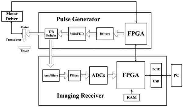
The block diagram of the real-time annular-array imaging platform for micro-ultrasound.
A. Pulse Generator
Two main functions were achieved in the designed pulse generator: the multi-channel high-voltage pulse generation and the transmit beamforming. All of the channels were controlled individually for dynamic focusing. A high-speed FPGA (Cyclone III, EP3C16F484C6N, Altera Corp., San Jose, CA) was used to control the multi-channel pulse generation and transmit beamforming. The focus of the transmitted beam can be programmed easily by the FPGA. The timing and spectrum characteristics of the pulse in different channels can also be controlled by the FPGA to match with the transducer. The pulse generator incorporated a bipolar pulse generation scheme. 8-channel MOSFET drivers (EL7158, Intersil Corp., Milpitas, CA) were employed to accomplish the voltage level shift and high current output to excite the 8 pairs of high-speed MOSFETs (TC6320, Supertex Inc., Sunnyvale, CA). The MOSFET pairs could offer more than 150 Vpp breakdown voltage and a 2 A output peak current, which made them suitable to produce the high-voltage pulse for micro-ultrasound. The T/R switch was achieved by the crossed diode bridge to block the reflected signal from the transducer. The FPGA also controlled the movement of the motor for cross-sectional scanning.
B. Imaging Receiver
The imaging receiver for the array system should have the capability of multi-channel signal amplification, acquisition, and receive beamforming. The designed imaging receiver for the annular-array platform incorporated 8-channel echo signal processing circuitry which could accomplish the real-time image processing including the signal amplification, data acquisition, digital signal processing, and fast data transfer. All of the channels were controlled individually for dynamic focusing. In detail, low-noise amplifiers (THS4509, Texas Instruments Inc., Dallas, TX) were employed for ultrasound signal amplification. High-speed ADCs (ADS58C48, Texas Instruments Inc.) were utilized for ultrasound data acquisition. Each ADC component contained a quad-channel 11-bit ADC with a sampling rate of up to 200 mega-samples per second (MSPS). After the digitization, the digital signal was transferred to FPGA through a low-voltage differential signaling (LVDS) bus. A high-performance FPGA (Stratix II EP2S60F672I4, Altera Corp., San Jose, CA) was employed for real-time image processing. It could process 8 channels of raw RF ADC data simultaneously. Programmable algorithms could be achieved, such as band-pass filter, dynamic beamformer, envelope detector, and digital scan converter for various applications. A 128-Mbit synchronous dynamic random access memory (SDRAM) (MT48LC8M16A2, Micron Technology Inc., Boise, ID) was configured to the FPGA for memory extension. Finally, the processed image data were transferred to a computer through a USB interface component (CY68013A, Cypress Semiconductor Corp., San Jose, CA) or a PCIE interface component (PEX8311, PLX Technology Inc., Sunnyvale, CA) for displaying or post-processing. Raw RF data could also be transferred to the computer.
C. Beamformer Algorithms
By controlling the signal delay of each element in an annular-array transducer, the ultrasound beam can be focused electronically at different depths. Dynamic focusing can be achieved by the digital beamformer throughout the depth. As a result, the depth-of-field is enlarged by multi-focal zone strategies. The ultrasound beamformer in the proposed annular-array imaging platform consists of the transmit beamformer and the receive beamformer, which are shown in Fig. 2.
Fig. 2.
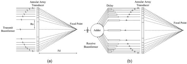
Principle of the (a) transmit beamformer and (b) receive beamformer in the proposed annular-array imaging platform.
The transmit beamformer manipulates the time delay of pulse generation in each channel to make the pulses reach the focal point simultaneously. The outer ring should be excited first, followed by the inner rings. The time delay between each channel is calculated as
| (1) |
where n is the number of rings and R(n) is the radius of the nth ring. Fd is the distance between array and the target focal point. c is the sound speed in the target tissue. The designed transmit beamformer controlled individual channels according to the time delay calculated by (1).
A combination method with coarse delay and fine delay was used for receive beamforming. The coarse delay was calculated by the integer multiplication of the sampling interval (5 ns at 200 MHz sampling frequency). Fine delay was achieved by a fractional delay filter, which could delay a fraction of the sampling interval (e.g., 0.1 × 5 ns = 0.5 ns). The fractional delay filter, usually achieved by an interpolation algorithm, provided a useful method for fine-tuning of the sampling signals to achieve better beamforming. A Lagrange interpolation algorithm was employed in this platform to achieve the fractional delay filter [35], [36]. The algorithm can be described by
| (2) |
where D is the desired total delay and N is the order of the filter. An eighth-order filter was used in this platform. Nine group delays were achieved from 0.1× to 0.9× sampling intervals, with a step of 0.1× sampling interval, as shown in Fig. 3. The delayed signal was a simulated ultrasonic echo signal with 35 MHz center frequency and 83% bandwidth. The black solid line represents the original data. It is delayed by 9 different times at steps of 0.1× the sampling interval. The waveform in the fractional sampling interval is acquired by this algorithm. To quantitatively analyze the accuracy of the fractional delay filter, the simulated ultrasonic echo signal was up-sampled to 2 GHz. The fractional delayed data and up-sampled data were then compared. The maximum difference for all of the data was 0.31% between these two methods.
Fig. 3.
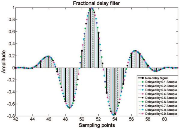
The simulated fractional delay waveform. The solid black line is the original ultrasonic echo signal with 35 MHz center frequency and 200 MHz sampling frequency. It was delayed by 9 times with steps of 0.1× the sampling interval.
D. FPGA Implementation
As a field-programmable microprocessor, the FPGA is highly programmable for various micro-ultrasound imaging applications. It can significantly improve the system flexibility and diversity by programmable and reconfigurable algorithms [20]. Fig. 4 shows the detailed structure of the implemented algorithms for real-time annular-array imaging. The band-pass filters are used to remove the noise out of spectrum of interest in each channel. The beamformer is used for dynamic beamforming of the 8-channel ultrasound signal. The 8-channel ultrasound signal was converged to a 1-channel signal after the beamformer. The signal is then sent to the envelope detector for envelope extraction. The envelope data then undergo digital scan conversion and logarithmic compression for coordination conversion and data compression, respectively. Finally, image data are sent to a personal computer through a PCIE or USB interface for display and storage. The entire algorithms in the FPGA can be changed according to the practical applications.
Fig. 4.
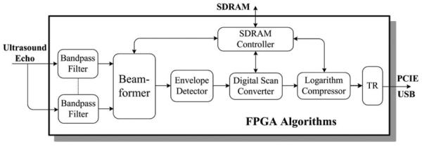
The algorithms implemented in the field-programmable gate array (FPGA) for real-time annular-array imaging.
The beamformer algorithm is achieved in the FPGA for fast field computation. Fig. 5 shows the block diagram of the digital beamformer algorithm in the FPGA. Coarse delay is applied first to the 8-channel signal. Fractional delay is then achieved using a Lagrange interpolation algorithm. The delay parameters are configured dynamically by the computer. An 8-channel adder is employed after precise delay. After the summation of the 8-channel delayed data, the 1-channel ultrasound data are buffered temporally for multi-focal zone imaging. The data are sent out for further image processing after the acquisition of multi-focal zone data.
Fig. 5.
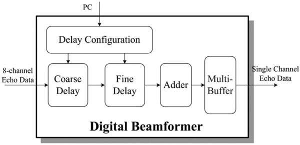
Block diagram of the digital beamformer in the field-programmable gate array (FPGA) for real-time annular-array imaging.
E. Transducer
The annular-array transducer in this platform is shown in Fig. 6. It was fixed onto a motor connector. It was designed with an interdigital bonded 1–3 composite material consisting of 8 elements [30]. The final composite had 19-μm-wide posts separated by 6-μm-wide polymer kerfs. The epoxy was used for both the matching and backing layers and a flexible circuit was used for interconnection. The flexible circuit and backing layer were placed inside a custom-machined brass housing. The average center frequency of the transducer was 33.5 MHz and the −6-dB bandwidth was 57%, as estimated from the measured pulse-echo response. The average insertion loss was 14.3 dB, and the maximum crosstalk between the nearest-neighbor elements was less than −37 dB. The aperture size was about 3.1 mm.
Fig. 6.
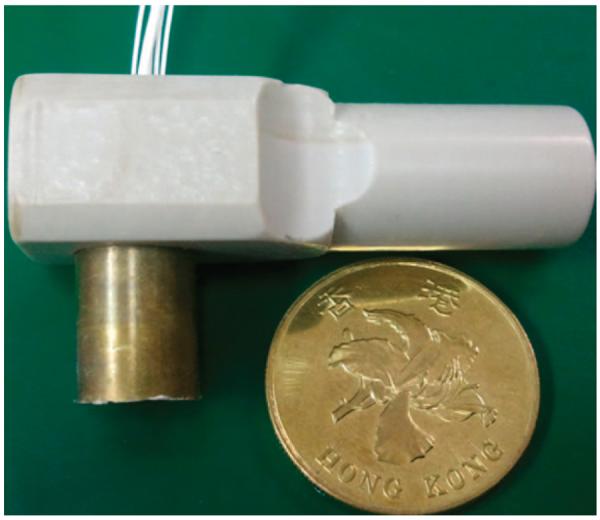
Annular-array transducer with 8 elements using an interdigital bonded 1–3 composite.
F. Test Scheme
The setup to test the annular-array-based imaging platform consisted of two 240-MHz function generators (AFG3251, Tektronix Inc., Beaverton, OR) and a 20-GS/s digital oscilloscope (LeCroy Wavepro 715Zi, LeCroy Corp., Chestnut Ridge, NY). The hardware performance was tested extensively, including the gain, the noise floor, the dynamic range, and the transmission error. The gain in the receiver was tested by the function generator and the oscilloscope. The noise floor was measured as the input known signal that just cannot be recognized in the receiver. Given the maximum input of the ADC (2 Vpp), the dynamic range could be derived from dividing the maximum input signal by the noise floor. 8-channel signal acquisition circuits might produce different transmission times. Two function generators were used to generate synchronous sinusoidal signal to different channels to test the transmission time error.
The data transfer speed between the imaging receiver and the PC was evaluated first for the frame rate test. The FPGA in the imaging receiver was programmed to send a known data sequence to the PC. The data transfer speed was calculated by dividing the amount of received data with the elapsed time. To evaluate the frame rate of the platform, a burst of sinusoidal signal with high pulse repetition frequency was generated by a function generator and sent to the platform. These signals were acquired by FPGA and sent to the PC through the PCIE or USB interface after forming images. A frame counter in the PC calculated the frame rate of the platform in terms of number of processed images per second.
A single-element focused transducer was used for imaging comparison. The transducer was a 40-MHz transducer with a focal length of 6.3 mm. The −6-dB bandwidth was 108%. One channel circuit in the proposed 8-channel annular-array platform was used for single-element imaging. The pulse generation and echo receiver scheme were same with the annular-array processing excluding the beamformer algorithm. A high-precision servo motor (TSL-2504, Techsoft Motion, Shenzhen, China) was used for sectional scan.
The resolution and depth-of-field tests were conducted to demonstrate the performance of the designed annular-array imaging platform. A wire phantom consisting of several 20-μm-diameter tungsten wires (California Fine Wire Co., Grover Beach, CA) was used to test the imaging resolution. The wire images, which were acquired at different depths, were aligned on the same axis for easy comparison. The quantitative measurements of the axial resolution and lateral resolution were acquired from the wire phantom test. Comparison of imaging resolution between single-element imaging and annular-array imaging was made to demonstrate the performance of the proposed platform. A tissue-mimicking phantom with anechoic spheres was fabricated to test the depth-of-field improvement of the annular-array imaging platform. The phantom fabrication procedure followed Madsen's method [37]. The phantom could generate tissue mimicking attenuation and backscattering. Anechoic spheres were fabricated separately and dispersed randomly in the phantom to test the platform resolution and depth-of-field. The size of the anechoic spheres was in the range of 280 to 350 μm, controlled by two dedicated sieves (Fisherbrand sieves, Fisher Scientific, Pittsburgh, PA). The contrast-to-noise ratio (CNR) of the anechoic spheres against the background, which was described in detail by Filoux et al. [38], was used to evaluate the improvement of depth-of-field by the proposed imaging platform.
III. Results
The platform prototype for the programmable, real-time annular-array imaging is shown in Fig. 7. Fig. 7(a) shows the 8-channel pulse generator in an 8-layer PCB. It includes the FPGA, MOSFETs, and MOSFET drivers. Fig. 7(b) shows the 8-channel digital imaging receiver. It is a 10-layer PCB design incorporating low-noise frontend electronics, ADCs, and high-speed FPGA. The high-speed PCIE interface and USB interface are also incorporated for compact implementation.
Fig. 7.
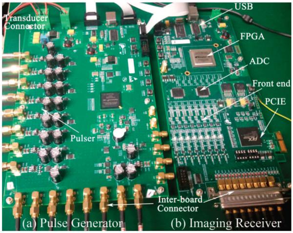
Photograph of prototype for annular-array imaging platform. (a) 8-channel pulse generator based on electronics and eight-layer printed circuit board (PCB), (b) 8-channel digital imaging receiver based on electronics and 10-layer PCB.
A. Platform Performance
The platform achieved very uniform gain among different channels. Fig. 8 shows the platform gain versus frequency in different channels. The gain of the receiver is about 47 dB and the difference of gain in different channels is lower than ±1 dB in the frequency range of 20 to 80 MHz.
Fig. 8.
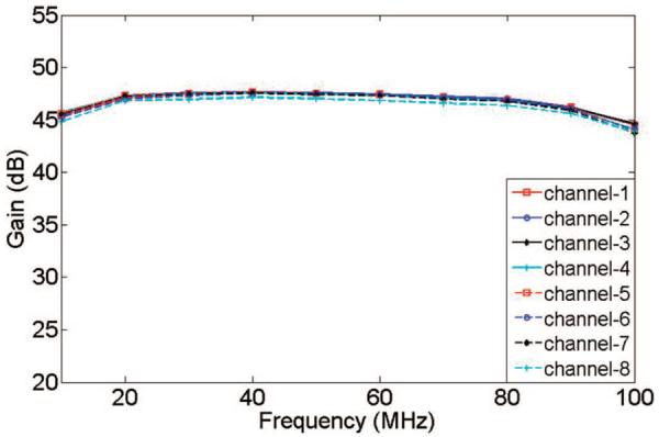
Gain measurements in the 8-channel imaging receiver.
Table I summarizes the performance of the proposed annular-array imaging platform. The amplitude of the high-voltage pulse can be higher than 120 V for the micro-ultrasound imaging. The noise floor is lower than 28 μV. Given the input range of the high-speed ADC (2 Vpp), the dynamic range of the front-end electronics in the annular-array platform is higher than 50 dB. The transmission time errors of different channels are less than ±0.5 ns. The precisions of the transmit and receive beamformers are 2.5 ns and 0.5 ns, respectively. The data transfer speeds are higher than 150 MByte/s and 20 MByte/s for the PCIE or USB interfaces, respectively. The frame rate of the platform is higher than 25 images per second for the image data size of 2048 × 400 × 16 bits using the PCIE interface.
TABLE I.
Electronics Performance of the Proposed Platform.
| Articles | Performance |
|---|---|
| Frequency range | 20–80 MHz |
| High-volt age pulse | Higher than 120 V |
| Gain | 47 dB |
| Gain flatness | Less than ±1 dB |
| Analog-to-digital converter | 11 bits, 200 MSPS |
| Front-end dynamic range | 50 dB |
| Transmission time error | Less than ±0.5 ns |
| Precision of transmit beamformer | 2.5 ns |
| Precision of receive beamformer | 0.5 ns |
| Data transferring speed | 150 MByte/s (PCIE) |
| 20 MByte/s (USB) |
Crosstalk in this platform consists of transducer crosstalk and hardware crosstalk. The maximum crosstalk between the adjacent elements in the transducer was less than −37 dB [30]. A 5-cycle sinusoidal 50-MHz signal was generated by a function generator and was fed to the different channels of the platform to test hardware crosstalk. The amplitude of the test signal is higher than 2 V after the amplifier. There is no visible sinusoidal signal coupled to the adjacent channels measured by the oscilloscope. The hardware crosstalk can be neglected.
B. Resolution Evaluation
The image resolution was evaluated by customized tungsten wire phantom. The ultrasound images of this wire phantom acquired using single-element transducer imaging and annular-array imaging are shown in Fig. 9. The wire images were acquired at different depths and were aligned on same axis for easy comparison. The annular-array imaging platform could maintain very uniform lateral resolution throughout the imaging depth. Four focal zones were used in this test.
Fig. 9.
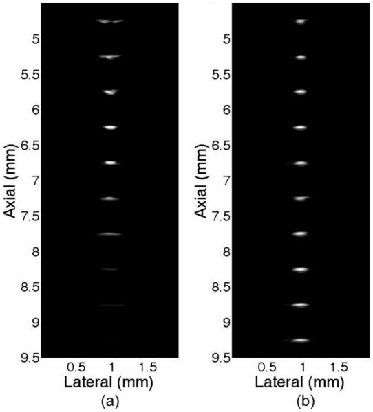
Comparison of wire phantom images using (a) single-element transducer imaging and (b) annular-array imaging.
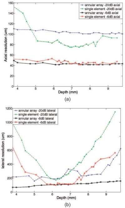
Fig. 10 shows the quantitative measurements of the axial resolution and lateral resolution by two imaging methods for the wire phantom images which were shown in Fig. 9. The −6-dB axial resolution was similar for the single-element transducer imaging and annular-array imaging. Single-element transducer imaging has better resolution than annular-array imaging for −20-dB axial resolution. The annular-array imaging has significant improvement for lateral resolution throughout the field of view. Although the −6-dB lateral resolution can be lower than 120 μm in single-element transducer imaging, it is decreased sharply outside the focal zone. Such high resolution can only be maintained about 1.7 mm around the focal point. The μ6-dB lateral resolution can be maintained more uniformly in the annular-array imaging. It can be maintained to be lower than 120 μm around 4.2 mm imaging depth, which has significant improvement (247% increases) compared with single-element transducer imaging.
Fig. 10.
Comparison of (a) axial resolution and (b) lateral resolution between single-element imaging and annular-array imaging.
C. Tissue-Mimicking Phantom Evaluation
A tissue-mimicking phantom with anechoic spheres was used to further test the imaging quality of the proposed annular-array platform. Fig. 11 shows the phantom images acquired by different ultrasound systems. The black circular dots in the images are the anechoic spheres. Fig. 11(a) shows the image which was acquired by a single-element focused transducer with 1-channel electronics in the proposed 8-channel array platform. The phantom image which is shown in Fig. 11(b) was acquired by a commercial micro-ultrasound scanner (Vevo 770, RMV-704, 40 MHz, VisualSonics Inc., Toronto, ON, Canada), The overall image quality of the two single-element systems is similar in terms of noise level, penetration depth, spatial resolution, and dynamic range. The annular-array platform can achieve dynamic focusing at different depths because it is highly programmable. Figs. 11(c) and 11(d) show the images with different focal depth in the phantom. The overall quality of images is similar to images which were acquired by the single-element transducer imaging systems. Fig. 11(e) shows the image with 4 focal zones acquired by the real-time annular-array imaging platform. The anechoic spheres can be visualized clearly in all focal zones. The calculated CNRs of the detected spheres were higher than 1.2 in the range of 3.8 to 8.7 mm imaging depth. The depth-of-field is extended by the proposed annular-array imaging platform.
Fig. 11.
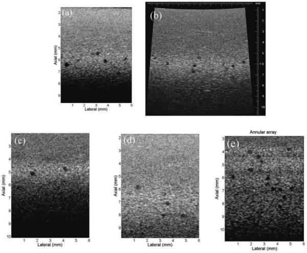
Tissue-mimicking phantom imaging using different systems. (a) Phantom image using single-element transducer and one channel electronics in the annular-array platform, (b) the same phantom image using Vevo 770 40-MHz transducer, (c) beamforming at 5-mm focal point using the annular-array platform, (d) beamforming at 7-mm focal point using the annular-array platform, and (e) phantom image with 4 focal zones using the annular-array platform.
IV. Discussion
A flexible annular-array imaging platform with programmable and real-time features for micro-ultrasound was developed and evaluated. The image quality was improved substantially with high flexibility using this platform. The depth-of-field was enlarged compared with single-element-transducer-based systems by incorporating both transmit beamforming and receive beamforming with dynamic focusing. It used fewer channels of arrays and circuits, which reduced the complexity and cost of the imaging system significantly compared with linear-array imaging systems.
The image processing algorithms were highly programmable, which supported great flexibility for various micro-ultrasound investigations; this can provide an easy implementation method for multi-modality investigation, such as combining ultrasound with photoacoustic imaging. The focus point could also be adjusted, which enables flexible operation for practical investigations. The platform supported nearly all types of annular transducers for micro-ultrasound, including flat annular-array transducers and focused annular-array transducers with flexible beamformer algorithms. Raw RF data before beamforming and after beamforming were also accessible by the proposed platform. The algorithms in the imaging receiver should be programmed for the high-speed RF data transfer mode. The imaging frame rate was about 25 images per second with post-beamforming RF data acquisition and about 3 images per second with 8-channel pre-beamforming data acquisition. The designed platform supported a flexible number of multi-channel signal acquisition and processing. Each channel could be controlled individually for pulse excitation and imaging data acquisition. This may enable dual-frequency ultrasound imaging, which could balance well with resolution and penetration, and could be useful for endoscopic or intravascular diagnostic applications.
The platform supported high-speed image processing and data transfer; however, the motor is a limitation to achieving high-speed imaging at the current stage. The servo motor in the test can only support 6 images per second. A high-speed sweep motor would be adopted later to support real-time imaging. The number of focal zone in this platform was adjustable for specific requirements. Generally, more focal zones supported higher quality imaging. However, the imaging frame rate must be sacrificed accordingly. For high-frame-rate imaging, one focal zone in transmission, and multi-focal zone in receiving is a trade-off method to balance image quality and frame rate.
Acknowledgments
Financial support from the Hong Kong Research Grant Council (RGC) General Research Fund (GRF) (PolyU 5301/09E) and the National Institutes of Health (NIH) grant P41-EB2182 is gratefully acknowledged.
Biographies
 Weibao Qiu was born in Jilin Province, China. He received his B.S. degree from the Hefei University of Technology, Hefei, China, in 2004, and his M.S. degree from the State Key Laboratory of Precision Measurement Technology and Instruments, Tianjin University, Tianjin, China, in 2007. He worked at the RFId Research Center, ZTE Corporation, China, as a hardware/FPGA research engineer for two years after receiving his master's degree. He obtained his Ph.D. degree from the Interdisciplinary Division of Biomedical Engineering, The Hong Kong Polytechnic University, in 2012. He is currently an associate professor at the Shenzhen Institutes of Advanced Technology, Chinese Academy of Sciences, China. His research interests include ultrasound imaging and electronics, high-frequency ultrasound imaging, intravascular imaging, endoscopic imaging, multi-modality imaging, and Doppler imaging.
 Yanyan Yu was born in Jilin Province, China. She received her B.S. and M.S. degrees from the Hefei University of Technology, Hefei, China, in 2006 and 2009, respectively. She worked at Hefei Meiya Optoelectronic Technology Inc., China, as an image processing software engineer for nearly one year after receiving her master's degree. She is currently working as a research assistant in the Interdisciplinary Division of Biomedical Engineering, The Hong Kong Polytechnic University, Hong Kong, China. Her research interests include digital image processing, ultrasonic imaging, and the theory and applications of the acoustic radiation force.
 Hamid Reza Chabok received his B.S. degree in mechanical engineering (manufacturing) from Tehran Polytechnic in 2000, and received three M.S. degrees: in mechanical engineering (robotics) from sharif University of Technology in 2003, and two from the University of Southern california (USC), Los Angeles, CA, in industrial and systems engineering in 2007 and in biomedical engineering in 2011. He finally obtained his Ph.D. degree in medical ultrasound imaging transducers from the NIH Resource Center for Medical Ultrasonic Transducer Technology at USC in 2011. His interests include high-frequency ultrasonic transducers and arrays, and digital methods for fabrication of piezoelectric materials and composites for medical imaging applications.
 Cheng Liu was born in Wuhan, China, in 1985. He received the B.Eng. degree in biomedical engineering in 2009 from the Southern Medical University, Guangzhou, China. He is currently a research M.Phil. student in the Interdisciplinary Division of Biomedical Engineering, The Hong Kong Polytechnic University, Hong Kong, China. His research interests include quantitative ultrasound system and tissue characterization.
 Fu Keung Tsang was born in Dongguan, China, in 1987. He received the B.S. degree in biomedical engineering from The Hong Kong Polytechnic University, Kowloon, Hong Kong, in 2010. He is currently a research assistant in the Interdisciplinary Division of Biomedical Engineering, The Hong Kong Polytechnic University. His research interests include ultrasound coded excitation imaging and small animal imaging.
 Qifa Zhou received his Ph.D degree from the Department of Electronic Materials and Engineering at Xi'an Jiaotong University, China, in 1993. He is currently a Research Professor at the NIH Resource on Medical Ultrasonic Transducer Technology and the Department of Biomedical Engineering at the University of Southern California (USC), Los Angeles, CA. Before joining USC in 2002, he worked in the Department of Physics at Zhongshan University of China, the Department of Applied Physics at Hong Kong Polytechnic University, and the Materials Research Laboratory at The Pennsylvania State University.
Dr. Zhou is a senior member of IEEE (UFFC Society) and a member of the UFFC Society's Ferroelectric Committee. He is also a member of the Technical Program Committee of the IEEE International Ultrasonics Symposium. He is an Associate Editor of the IEEE Transactions on Ultrasonics, Ferroelectrics, and Frequency Control. His current research interests include the development of ferroelectric thin films, MEMS technology, nano-composites, modeling and fabrication of high-frequency ultrasound transducers and arrays for medical imaging applications, and photoacoustic imaging. He has published more than 100 papers in these areas.
 K. Kirk Shung obtained a B.S. degree in electrical engineering from Cheng-Kung University in Taiwan in 1968; an M.S. degree in electrical engineering from the University of Missouri, Columbia, MO, in 1970; and a Ph.D. degree in electrical engineering from the University of Washington, Seattle, WA, in 1975. He taught at The Pennsylvania State University, University Park, PA, for 23 years before moving to the Department of Biomedical Engineering, University of Southern California, Los Angeles, CA, as a professor in 2002. He has been the director of the NIH Resource on Medical Ultrasonic Transducer Technology since 1997.
Dr. Shung is a Life Fellow of IEEE and a fellow of the Acoustical Society of America and the American Institute of Ultrasound in Medicine. He is a founding fellow of the American Institute of Medical and Biological Engineering. He received the IEEE Engineering in Medicine and Biology Society Early Career Award in 1985 and was the coauthor of a paper that received the best paper award for the IEEE Transactions on Ultrasonics, Ferroelectrics, and Frequency Control (UFFC) in 2000. He was elected an outstanding alumnus of Cheng-Kung University in Taiwan in 2001. He was selected as the distinguished lecturer for the IEEE UFFC society for 2002–2003. He received the Holmes Pioneer Award in Basic Science from the American Institute of Ultrasound in Medicine in 2010. He was selected to receive the academic career achievement award from the IEEE Engineering in Medicine and Biology society in 2011.
Dr. Shung has published more than 400 papers and book chapters. He is the author of the textbook Principles of Medical Imaging, published by Academic Press in 1992 and the textbook Diagnostic Ultrasound: Imaging and Blood Flow Measurements, published by CRC Press in 2005. He co-edited the book Ultrasonic Scattering by Biological Tissues, published by CRC Press in 1993. Dr. Shung's research interests are in ultrasonic transducers, high-frequency ultrasonic imaging, ultrasound microbeams, and ultrasonic scattering in tissues.
 Hairong Zheng received his B.S. degree from the Harbin Institute of Technology in 2000 and his Ph.D. degree in mechanical engineering from the University of Colorado at Boulder in 2006. He joined the University of California, Davis, first as a postdoctoral fellow, and then as project scientist in the Biomedical Engineering Department. Prof. Zheng has published more than 100 peer-reviewed journal papers and international conference proceedings. Prof. Zheng is a recipient of the American Heart Association Pre-Doctoral Fellowship (2005). Prof. Zheng is an IEEE senior member and is now director of the Paul C. Lauterbur Research Center for Biomedical Imaging, Shenzhen Institutes of Advanced Technology, Chinese Academy of Sciences. His research areas have been focused on developing ultrasonic techniques and systems for imaging, drug delivery, and therapy, and multimodality medical imaging systems.
 Lei Sun was born in Shenyang, China. He received his B.S. degree in electrical engineering from the University of Science and Technology of China, Hefei, China, in 1996, his M.S. degree in electrical engineering from the Chinese Academy of Sciences, Beijing, China, in 2000, and his Ph.D. degree in bioengineering from The Pennsylvania State University, University Park, PA, in 2004.
Currently, he is an Assistant Professor in the Interdisciplinary Division of Biomedical Engineering, Hong Kong Polytechnic University, Hong Kong, China. From 2004 to 2008, he was a Post-Doctoral Fellow and a Research Associate at the National Institutes of Health (NIH) Resource Center for Medical Ultrasonic Transducer Technology, University of Southern California, Los Angeles, CA. His research interests include ultrasonic and Doppler imaging, high-frequency ultrasound, magnetic-resonance-guided high-intensity focused ultrasound (HIFU), small animal imaging, cardiac imaging, ultrasonic tissue characterization, biomedical instrumentation, biomedical signal, and image processing.
References
- [1].Foster FS, Pavlin CJ, Harasiewicz KA, Christopher DA, Turnbull DH. Advances in ultrasound biomicroscopy. Ultrasound Med. Biol. 2000;26(no. 1):1–27. doi: 10.1016/s0301-5629(99)00096-4. [DOI] [PubMed] [Google Scholar]
- [2].Gazzard G, Friedman DS, Devereux JG, Chew P, Seah SK. A prospective ultrasound biomicroscopy evaluation of changes in anterior segment morphology after laser iridotomy in Asian eyes. Ophthalmology. 2003;110(no. 3):630–638. doi: 10.1016/S0161-6420(02)01893-6. [DOI] [PubMed] [Google Scholar]
- [3].Huang Y, Zheng Y, Leung SF, Choi AP. High frequency ultrasound assessment of skin fibrosis: Clinical results. Ultrasound Med. Biol. 2007;33(no. 8):1191–1198. doi: 10.1016/j.ultrasmedbio.2007.02.009. [DOI] [PubMed] [Google Scholar]
- [4].Vogt M, Ermert H. In vivo ultrasound biomicroscopy of skin: Spectral system characteristics and inverse filtering optimization. IEEE Trans. Ultrason. Ferroelectr. Freq. Control. 2007;54(no. 8):1551–1559. doi: 10.1109/tuffc.2007.425. [DOI] [PubMed] [Google Scholar]
- [5].de Korte CL, van der Steen AFW, Cespedes EI, Pasterkamp G, Carlier SG, Mastik F, Schoneveld AH, Serruys PW, Bom N. Characterization of plaque components and vulnerability with intravascular ultrasound elastography. Phys. Med. Biol. 2000;45(no. 6):1465–1475. doi: 10.1088/0031-9155/45/6/305. [DOI] [PubMed] [Google Scholar]
- [6].Qiu W, Chen Y, Li X, Yu Y, Cheng WF, Tsang FK, Zhou Q, Shung KK, Dai J, Sun L. An open system for intravascular ultrasound imaging. IEEE Trans. Ultrason. Ferroelectr. Freq. Control. 2012;59(no. 10):2201–2209. doi: 10.1109/TUFFC.2012.2446. [DOI] [PMC free article] [PubMed] [Google Scholar]
- [7].Silverman RH, Ketterling JA, Coleman DJ. High-frequency ultrasonic imaging of the anterior segment using an annular array transducer. Ophthalmology. 2007;114(no. 4):816–822. doi: 10.1016/j.ophtha.2006.07.050. [DOI] [PMC free article] [PubMed] [Google Scholar]
- [8].Hartmann M, Huisman J, Bose D, Jensen LO, Schoenhagen P, Mintz GS, Erbel R, von Birgelen C. Serial intravascular ultrasound assessment of changes in coronary atherosclerotic plaque dimensions and composition: An update. Eur. J. Echocardiogr. 2011;12(no. 4):313–321. doi: 10.1093/ejechocard/jer017. [DOI] [PubMed] [Google Scholar]
- [9].Cheung AM, Brown AS, Hastie LA, Cucevic V, Roy M, Lacefield JC, Fenster A, Foster FS. Three-dimensional ultrasound biomicroscopy for xenograft growth analysis. Ultrasound Med. Biol. 2005;31(no. 6):865–870. doi: 10.1016/j.ultrasmedbio.2005.03.003. [DOI] [PubMed] [Google Scholar]
- [10].Goessling W, North TE, Zon LI. Ultrasound biomicroscopy permits in vivo characterization of zebrafish liver tumors. Nat. Methods. 2007;4(no. 7):551–553. doi: 10.1038/nmeth1059. [DOI] [PubMed] [Google Scholar]
- [11].Zhou YQ, Foster FS, Nieman BJ, Davidson L, Chen XJ, Henkelman RM. Comprehensive transthoracic cardiac imaging in mice using ultrasound biomicroscopy with anatomical confirmation by magnetic resonance imaging. Physiol. Genomics. 2004;18(no. 2):232–244. doi: 10.1152/physiolgenomics.00026.2004. [DOI] [PubMed] [Google Scholar]
- [12].Du J, Zhang C, Liu J, Sidky C, Huang XP. A point mutation (R192H) in the C-terminus of human cardiac troponin I causes diastolic dysfunction in transgenic mice. Arch. Biochem. Biophys. 2006;456(no. 2):143–150. doi: 10.1016/j.abb.2006.08.018. [DOI] [PubMed] [Google Scholar]
- [13].Sun L, Lien C, Xu X, Shung KK. In vivo cardiac imaging of adult zebrafish using high frequency ultrasound (45–75 MHz) Ultrasound Med. Biol. 2008;34(no. 1):31–39. doi: 10.1016/j.ultrasmedbio.2007.07.002. [DOI] [PMC free article] [PubMed] [Google Scholar]
- [14].Zhou YQ, Foster FS, Qu DW, Zhang M, Harasiewicz KA, Adamson SL. Applications for multifrequency ultrasound biomicroscopy in mice from implantation to adulthood. Physiol. Genomics. 2002;10(no. 2):113–126. doi: 10.1152/physiolgenomics.00119.2001. [DOI] [PubMed] [Google Scholar]
- [15].Kulandavelu S, Qu D, Sunn N, Mu J, Rennie MY, Whiteley KJ, Walls JR, Bock NA, Sun JC, Covelli A, Sled JG, Adamson SL. Embryonic and neonatal phenotyping of genetically engineered mice. ILAR J. 2006;47(no. 2):103–117. doi: 10.1093/ilar.47.2.103. [DOI] [PubMed] [Google Scholar]
- [16].Foster FS, Zhang MY, Zhou YQ, Liu G, Mehi J, Cherin E, Harasiewicz KA, Starkoski BG, Zan L, Knapik DA, Adamson SL. A new ultrasound instrument for in vivo microimaging of mice. Ultrasound Med. Biol. 2002;28(no. 9):1165–1172. doi: 10.1016/s0301-5629(02)00567-7. [DOI] [PubMed] [Google Scholar]
- [17].Sun L, Richard WD, Cannata JM, Feng CC, Johnson JA, Yen JT, Shung KK. A high-frame rate high-frequency ultrasonic system for cardiac imaging in mice. IEEE Trans. Ultrason. Ferroelectr. Freq. Control. 2007;54(no. 8):1648–1655. doi: 10.1109/tuffc.2007.436. [DOI] [PubMed] [Google Scholar]
- [18].Sun L, Xu X, Richard WD, Feng C, Johnson JA, Shung KK. A high-frame rate duplex ultrasound biomicroscopy for small animal imaging In vivo. IEEE Trans. Biomed. Eng. 2008;55(no. 8):2039–2049. doi: 10.1109/TBME.2008.919110. [DOI] [PubMed] [Google Scholar]
- [19].Qiu W, Yu Y, Tsang FK, Sun L. A multi-functional, reconfigurable pulse generator for high frequency ultrasound imaging. IEEE Trans. Ultrason. Ferroelectr. Freq. Control. 2012;59(no. 7):1558–1567. doi: 10.1109/TUFFC.2012.2355. [DOI] [PubMed] [Google Scholar]
- [20].Qiu W, Yu Y, Tsang FK, Sun L. An FPGA based open platform for ultrasound biomicroscopy. IEEE Trans. Ultrason. Ferroelectr. Freq. Control. 2012;59(no. 7):1432–1442. doi: 10.1109/TUFFC.2012.2344. [DOI] [PubMed] [Google Scholar]
- [21].Hu C, Xu X, Cannata JM, Yen JT, Shung KK. Development of a real-time, high-frequency ultrasound digital beamformer for high-frequency linear array transducers. IEEE Trans. Ultrason. Ferroelectr. Freq. Control. 2006;53(no. 2):317–323. doi: 10.1109/tuffc.2006.1593370. [DOI] [PubMed] [Google Scholar]
- [22].Xu X, Sun L, Cannata JM, Yen JT, Shung KK. High-frequency ultrasound Doppler system for biomedical applications with a 30-MHz linear array. Ultrasound Med. Biol. 2008;34(no. 4):638–646. doi: 10.1016/j.ultrasmedbio.2007.09.012. [DOI] [PMC free article] [PubMed] [Google Scholar]
- [23].Zhang L, Xu X, Hu C, Sun L, Yen JT, Cannata JM, Shung KK. A high-frequency, high frame rate duplex ultrasound linear array imaging system for small animal imaging. IEEE Trans. Ultrason. Ferroelectr. Freq. Control. 2010;57(no. 7):1548–1557. doi: 10.1109/TUFFC.2010.1585. [DOI] [PMC free article] [PubMed] [Google Scholar]
- [24].Foster FS, Mehi J, Lukacs M, Hirson D, White C, Chaggares C, Needles A. A new 15–50 MHz array-based micro-ultrasound scanner for preclinical imaging. Ultrasound Med. Biol. 2009;35(no. 10):1700–1708. doi: 10.1016/j.ultrasmedbio.2009.04.012. [DOI] [PubMed] [Google Scholar]
- [25].Shung KK. Diagnostic Ultrasound: Imaging and Blood Flow Measurements. CRC Press; Boca Raton, FL: 2005. [Google Scholar]
- [26].Brown JA, Demore CEM, Lockwood GR. Design and fabrication of annular arrays for high frequency ultrasound. IEEE Trans. Ultrason. Ferroelectr. Freq. Control. 2004;51(no. 8):1010–1017. doi: 10.1109/tuffc.2004.1324405. [DOI] [PubMed] [Google Scholar]
- [27].Ketterling JA, Aristizabal O, Turnbull DH, Lizzi FL. Design and fabrication of a 40-MHz annular array transducer. IEEE Trans. Ultrason. Ferroelectr. Freq. Control. 2005;52(no. 4):672–681. doi: 10.1109/tuffc.2005.1428050. [DOI] [PMC free article] [PubMed] [Google Scholar]
- [28].Snook KA, Hu C, Shrout TR, Shung KK. High-frequency ultrasound annular array imaging, Part I: Array design and fabrication. IEEE Trans. Ultrason. Ferroelectr. Freq. Control. 2006;53(no. 2):300–308. doi: 10.1109/tuffc.2006.1593368. [DOI] [PubMed] [Google Scholar]
- [29].Gottlieb EJ, Cannata JM, Hu C, Shung KK. Development of a high-frequency (>50 MHz) copolymer annular-array, ultrasound transducer. IEEE Trans. Ultrason. Ferroelectr. Freq. Control. 2006;53(no. 5):1037–1045. doi: 10.1109/tuffc.2006.1632693. [DOI] [PubMed] [Google Scholar]
- [30].Chabok HR, Cannata JM, Kim HH, Williams JA, Park J, Shung KK. A high-frequency annular-array transducer using an interdigital bonded 1–3 composite. IEEE Trans. Ultrason. Ferroelectr. Freq. Control. 2011;58(no. 1):206–214. doi: 10.1109/TUFFC.2011.1787. [DOI] [PMC free article] [PubMed] [Google Scholar]
- [31].Liu C, Djutha F, Li X, Chen R, Zhou Q, Shung KK. Micromachined high frequency PMN-PT/epoxy 1–3 composite ultrasonic annular array. Ultrasonics. 2012;52(no. 4):497–502. doi: 10.1016/j.ultras.2011.11.001. [DOI] [PMC free article] [PubMed] [Google Scholar]
- [32].Brown JA, Lockwood GR. A digital beamformer for high-frequency annular arrays. IEEE Trans. Ultrason. Ferroelectr. Freq. Control. 2005;52(no. 8):1262–1269. doi: 10.1109/tuffc.2005.1509785. [DOI] [PubMed] [Google Scholar]
- [33].Hu CH, Snook KA, Cao PJ, Shung KK. High-frequency ultrasound annular array imaging, Part II: Digital beamformer design and imaging. IEEE Trans. Ultrason. Ferroelectr. Freq. Control. 2006;53(no. 2):309–316. doi: 10.1109/tuffc.2006.1593369. [DOI] [PubMed] [Google Scholar]
- [34].Ketterling JA, Ramachandran S, Aristizabal O. Operational verification of a 40-MHz annular array transducer. IEEE Trans. Ultrason. Ferroelectr. Freq. Control. 2006;53(no. 3):623–630. doi: 10.1109/tuffc.2006.1610571. [DOI] [PMC free article] [PubMed] [Google Scholar]
- [35].Laakso TI, Välimäki V, Karjalainen M, Laine UK. Splitting the unit delay—Tools for fractional delay filter design. IEEE Signal Process. Mag. 1996;13(no. 1):30–60. [Google Scholar]
- [36].Välimäki V, Laakso TI. Principles of fractional delay filters. Int. Acoustics, Speech, and Signal Processing Conf. 2000;6:3870–3873. [Google Scholar]
- [37].Madsen EL, Frank GR, McCormick MM, Deaner ME, Stiles TA. Anechoic sphere phantoms for estimating 3-D resolution of very-high-frequency ultrasound scanners. IEEE Trans. Ultrason. Ferroelectr. Freq. Control. 2010;57(no. 10):2284–2292. doi: 10.1109/TUFFC.2010.1689. [DOI] [PMC free article] [PubMed] [Google Scholar]
- [38].Filoux E, Mamou J, Aristizábal O, Ketterling JA. Characterization of the spatial resolution of different high-frequency imaging systems using a novel anechoic-sphere phantom. IEEE Trans. Ultrason. Ferroelectr. Freq. Control. 2011;58(no. 5):994–1005. doi: 10.1109/TUFFC.2011.1990. [DOI] [PMC free article] [PubMed] [Google Scholar]


