Abstract
3D biomaterial scaffolds with aligned architecture are of vital importance in tissue regeneration to mimic native tissue hierarchy and hence function. We demonstrate a generic method to produce aligned biomaterial scaffolds using the physics of directional ice freezing. Homogeneously aligned 3D silk scaffold with high porosity and alignment was demonstrated. The method can be adapted to a wide range of polymers and is devoid of any chemical reactions, thus avoiding potential complications associated with by-products and purification procedures. Subsequently, the 3D aligned system was tested for mechanical properties and cellular responses with chondrocytes and bone marrow derived human mesenchymal stem cells, assessing survival, proliferation and differentiation. In vivo tests suggested biocompatibility of the matrices for future tissue engineering applications, specifically in areas where high cellular alignment is needed.
Keywords: Silk, laminar scaffolds, alignment, freeze drying
Introduction
Since first proposed by Langer and Vacanti, scientific advances in biomaterials, stem cells, and understanding of biomimetic environments have created unique opportunities to fabricate tissues in vitro by combining engineered 3D matrices or “scaffolds”, cells, and biologically active molecules.1 However, for complex human tissues, traditional scaffolds fail to capture the multi-scale structural hierarchy inherent in biological tissues.2 As a result in vitro engineered tissues have yet to reach their functional equivalence (mechanical, biological, integration) with their native counterparts.
Tissue structure is critical to tissue function.3 Thus, recapitulation of native tissue structure and anatomic forms using biocompatible materials remains a key challenge.2,3 Particularly for load-bearing tissues, recapitulation of the complex architecture is critical to avoid long term graft failure due to lack of integration and to attain native mechanical functions.3 As a result, materials with aligned microstructures having micrometer range pores and high interconnectivity are desired in tissue regeneration to be subsequently modified with biological cells to attain organized cellular alignment.
This type of organized cellular alignment is critical to controlling tissue microarchitecture and to attain native biological functions.3 Although a multitude of techniques have been described to control cellular alignment in 2D, recapitulating the cellular alignment of highly organized native tissues in 3D engineered tissues remains a challenge. In traditional cellular engineering, 3D matrices or scaffolds play a vital role providing the base substratum for growing cells to adhere and proliferate.4 Thus, a useful scaffold should have desired mechanical properties, be non-toxic to cells and adjoining tissues, biocompatible, and the biodegradation rate should match the rate of new tissue formation.5–10 Further to provide adequate space for growing cells, 3D scaffolds should have high porosity and optimal interconnectivity for cells to migrate and grow while maintaining good mass transfer.4, 11, 12 Numerous methods have been reported to attain such 3D scaffold features and properties for tissue regeneration including gas-foaming, three-dimensional printing, thermal induced phase separation, electrospinning and freeze drying.13–18 Mostly these methods generate random porous structures, while electrospinning offers alignment but lacks significant 3D structural features with high porosity and alignment.19, 20
Scaffold fabrication using water as a porogenic template is a benign and versatile route towards the preparation of porous aligned matrices.21–24 Scaffolds of multiscale porosity and pore size have been reported by controlling the freezing temperature of water.4 This method has been further adapted to produce directional freezing for sol-gel synthesis to produce aligned silica fibers, silica microhoneycombs and other aligned ceramics.21–24 Similarly using directional freeze-drying, various aligned porous materials have been fabricated, including organic, inorganic and composite materials, of which Al2O3, SiO2 and TiO2 are the most reported.25–32
In the present study, Bombyx mori silk is used due to its desirable properties including biocompatibility with low inflammatory and immunogenic responses.6, 33–35 The unique β-sheet (crystalline)-rich structure of silk imparts high stiffness and toughness to fabricated biomaterials, making it a suitable choice for load bearing applications.33 Additionally, due to the amphiphilic features, post processing of silk into various material formats including 3D scaffolds is feasible with tunable degradation properties.6, 36 Further, silk has achieved FDA approval for some medical devices.
In the present study, the goal was to improve the current directional freezing technique to achieve 3D silk scaffolds with homogenous laminar pores and high porosity. Towards this goal, a simple prototype device for polymer freezing was developed to fabricate scaffolds, aligned horizontally as compared to conventional vertical freezing, thus avoiding heterogeneity in alignment and pores. The effects of silk protein content on porosity and pore size, along with alignment, on compressive properties were investigated. Subsequent studies focused on the compatibility of these laminar systems for human chondrocyte survival and bone marrow stem cell differentiation, including in vivo testing towards tissue engineering applications.
Materials and Methods
Silk processing
Silk solution was prepared using Bombyx mori silkworm cocoons supplied by Tajima Shoji Co (Yokohama, Japan) according to protocols described in our previous studies.37, 38 Briefly, cut pieces of cocoons were degummed in boiling 0.02M sodium carbonate solution for 20 min followed by thorough washing in deionized water and air drying. After air drying, the degummed silk fibers was dissolved in 9.3 M LiBr solution (Sigma, St. Louis, MO, USA) at 60°C yielding a 20% w/v solution. This solution was subsequently dialyzed against water using Slide a-Lyzer dialysis cassettes (Pierce, MWCO 3,500) for three days with frequent change of water. The final concentration of the aqueous silk fibroin solution was 8 wt%. Silk concentrate lower than 8 wt% was made by diluting with deionized water.
Preparation of polydimethylsiloxane (PDMS) freezing chamber
To prepare laminar silk scaffolds, a special shallow chamber was casted out of PDMS. The base polymer, PDMS (GE Plastics, Pittsfield, MA), was mixed with curing agent in the ratio of 9:1. The mixture was degassed and poured into a cast and allowed to dry. The design consisted of a hollow chamber (8 × 4 × 2 cm) divided into two parts by a thin (1 mm) copper metal plate (Figure 1). This metal plate acts as the ignition point for freezing of silk in one chamber when liquid nitrogen is poured into the other chamber.
Figure 1.
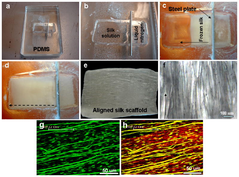
(a–d) Images show fabricated polydimethylsiloxane (PDMS) directional freezing prototype chamber and freezing steps; (e–f) fabricated aligned scaffold with aligned pores; (g–h) hMSC alignment on scaffolds showing nuclei (green dots) and actin fibers (red). Scale bar 50 microns.
Laminar silk scaffold fabrication
To fabricate laminar scaffolds, silk solution (8 wt %) was poured into one chamber of the PDMS mold. Liquid nitrogen was slowly filled in the other chamber. Liquid nitrogen quickly cooled the metal plate which in turn cools the silk solution leading to directional freezing (inside to outside) (Figure 1). Liquid nitrogen was replenished periodically (up to the top level) until all of the silk solution was frozen. The PDMS chamber was then transferred to a lyophilizer for silk drying. Dried silk scaffold was then removed from the PDMS mold and immersed in 80% methanol overnight. The top and bottom thin skins were removed using a surgical blade to open up pores. The scaffolds were either stored in methanol 70% (v/v) or directly used for cell culture after sectioning into desired sizes.
Scanning electron microscopy (SEM)
Fractured sections of laminar silk scaffolds were obtained in liquid nitrogen using a razor blade. The fracture surfaces were sputter coated with Pt/Pd and morphology was examined with a Field Emission Scanning Electron Microscope (FESEM) Zeiss Ultra55 (Carl Zeiss AG, Germany). Pore size and wall thickness of silk scaffolds were analyzed with ImageJ 1.40 (Wayne Rasband).
Porosity measurement by liquid displacement
Porosity of silk laminar scaffolds fabricated using different wt% silk was determined via liquid displacement with hexane, as previously reported.4 After fabrication, the scaffolds were lyophilized and then immersed in a graduated cylinder of known volume of hexane (V1). A series of quick evacuation–depressurization cycles were performed to completely evacuate entrapped air and to impregnate the scaffold with hexane; thereafter, the volume in the cylinder was recorded (V2). The hexane impregnated scaffold was removed and the volume was recorded again (V3). Any change of volume due to evaporation during the evacuation cycles was checked using another cylinder without the scaffold. The porosity of the scaffold is expressed as: Porosity = [(V1 − V3)/(V2 − V3)] × 100%
Mechanical properties
Unconfined compressive mechanical testing of hydrated laminar silk scaffolds was performed on an Instron 3366 (Norwood, MA, USA) testing frame equipped with a 0.1 kN load cell. Tests for all scaffold types (4, 6 and 8 wt% silk) were carried out in 0.1 (M) PBS bath (Biopuls, Instron Corp.) at 37°C under hydrated conditions. For compressive testing, silk cylindrical scaffold were punched out in two different directions i.e. one parallel to the pore direction/orientation and second perpendicular to pore orientation with overall dimensions of 4 mm diameter and 6 mm height. All tests were accessed with a conventional open-sided (nonconfined) configuration and were performed using a displacement control mode at a rate of 5 mm/min following ASTM standard D1621-04a (Standard Test Method for Compressive Properties of Rigid Cellular Plastics). After the compression tests, the compressive stress and strain were graphed based on the measured cross-sectional area and sample height (nominal ~4–5 mm, measured automatically at 0.02N tare load), respectively. The elastic modulus was calculated based on a linear regression fitting of the small strain section that preceded an identifiable plateau region.
Isolation of human mesenchymal stem cells (hMSC)
Human bone marrow-derived mesenchymal stem cell (hMSC) isolation and expansion was carried out following our previously published protocols.37 A 25 ml bone marrow aspirate (Lonza, Walkersville, MD) was obtained from a 27 year old male donor and was diluted in 75 ml of PBS. Cells were separated by density gradient centrifugation and 20 ml aliquots of the bone marrow suspension were overlaid onto a poly-sucrose gradient (1.077 g/cm3, Histopaque, Sigma) and centrifuged at 800 g for 30 min at room temperature. The cell pellet was resuspended in Eagle’s Minimum Essential Medium (α-MEM: Gibco BRL, Grand Island, NY) supplemented with 10% fetal bovine serum (FBS, Gibco BRL), 100 U/mL penicillin G (Gibco BRL), and 100 μg/mL streptomycin (Gibco BRL). Cell number and viability were determined using a trypan blue exclusion test. The resuspended cells were plated at a density of 1.5 × 10⁵ cells/cm2 and placed in a 5% CO2 incubator at 37°C. The culture medium was changed every other day and cells were passaged three times (P3) before use in experiments.
Cell proliferation, differentiation and matrix alignment on laminar silk scaffolds
To evaluate cellular proliferation, extracellular matrix (ECM) alignment and differentiation potential within laminar silk scaffolds (chondrogenic and adipogenic), approximately, 106 hMSCs were seeded onto individual silk laminar scaffold of dimension 5 × 5 × 1 mm per group. After seeding, growth medium was added (DMEM + 10% FBS + antibiotics) and samples were cultured for 3 days at 37°C, 5% CO2 before transferring into respective differentiation media. Control experiment contained scaffolds with equal hMSCs cultured in growth medium. Separately, primary human chondrocytes (hCH) (Lonza, Walkersville, MD) were seeded on laminar scaffolds (106 cells/scaffold). hMSC and hCH proliferation on 3D laminar silk-scaffolds were monitored by Alamar blue dye reduction assay (Invitrogen, USA) after 1, 2, 3 and 4 weeks following manufacturers’ protocol.
Chondrogenesis
hMSCs and hCH were cultured (individually) in a chemically defined medium (DMEM + 10% FBS, 0.1 μM dexamethasone, 50 μg/ml ascorbate 2-phosphate, 40 μg/ml L-proline, 100 μg/ml sodium pyruvate, 1x ITS (6.25 μg/ml insulin, 6.25 μg/ml transferrin, 6.25 ng/ml selenous acid) (Sigma, St. Louis, MO, USA), 1.25 mg/ml bovine serum albumin and 5.35 μg/ml linoleic acid with 10 ng/ml TGF-β3 (R&D systems, Minneapolis, MN) in non-tissue culture treated 12-well plates). Half of the medium was changed every two days.
Adipogenesis
hMSC seeded scaffolds were cultured in adipogenic media consisting of DMEM supplemented with 0.5 mM isobutylmethylxanthine (IBMX), 1 μM dexamethazone, 10 μM insulin and 200 μM indomethacin (Sigma–Aldrich, St. Louis, MO, USA) and Pen-Streptomycin. Fresh medium was replenished every two days.
In vivo subcutaneous implantation in mice
All procedures were conducted under animal care protocols approved by Tufts Institutional Animal Care and Use Committee. All animals used in this study were five to seven weeks old balb/c female mice (Charles River breeding labs). The mice were distributed into two time points: 1 and 4 weeks. The mice were randomly assigned to each time point and acellular laminar silk scaffold samples of dimensions 5 × 5 × 1 mm were subcutaneously implanted in lateral subcutaneous pockets of each mouse under general anesthesia using a mixture of oxygen (0.6 l/min) and 1.5–3 vol% of Isofluran. The healing process at the incision region was coarse monitored during all study period and no deaths were registered during the experiment. To check for inflammatory responses, mice were euthanized after 1 and 4 weeks post-implantation and samples collected along with the overlying tissue for histological examination.
Histology and staining
Individual harvested scaffolds were washed in PBS followed by fixation in 10% neutral buffered formalin for 24 h before histological analysis. Samples were dehydrated through a series of graded ethanol, embedded in paraffin, and sectioned at 5 μm thickness. For histological evaluation, sections were deparaffinized, rehydrated through a series of graded ethanol, and stained. For scaffolds cultured with cells (hMSC and hCH), serial sections were stained with Alcian blue (Sigma–Aldrich, St. Louis, MO, USA) for detection of sulfated proteoglycans in the matrix and Oil Red-O (Sigma–Aldrich, St. Louis, MO, USA) to assess presence of neutral lipids. For in vivo scaffold samples, following staining with hematoxylin and eosin (H&E), histological sections were examined to assess the extent of degradation and for local inflammatory responses at the implant-host interface, such as for neovascularisation, fibrosis and the presence of inflammatory cells.
Imaging
hMSC, hCH survival, attachment and alignment on individual laminar silk scaffold was assessed using confocal microscopy. For imaging, each scaffold was seeded with 106 cells (hMSCs and hCH seeded separately), and cultured for 7 days at 37°C, 5% CO2 in basal growth medium as mentioned above to allow cells to adhere and align on the matrices. On imaging day, scaffolds were washed once with PBS (pH 7.4) followed by staining with Live-Dead dye (Invitrogen, USA) following manufacturer’s protocol. To visualize actin and nuclei, scaffolds were fixed in 3.7% formaldehyde in PBS for 10 min. The samples were further washed with PBS and preincubated with 1% BSA for 30 min. The constructs were then permeabilized using 0.1% Triton X-100 for 5 min. Incubated with Rhodamine-phalloidin (Invitrogen, USA) for 20 min at room temperature followed by PBS washing and counterstaining with Hoechst 33342 (Invitrogen, USA) for 30 min. Images from stained constructs were obtained using a confocal laser scanning microscope (Leica SP2 inverted microscope) equipped with argon (488 nm) and HeNe (534 nm) lasers.
Statistical analysis
All quantitative experiments were run at least in triplicate (unless specified), and results are expressed as mean ± standard deviation. Statistical analysis of data was performed by one-way analysis of variance (ANOVA). Differences between groups of #p ≤ 0.05 were considered statistically significant and ##p ≤ 0.01 as highly significant.
Results and Discussion
Special chamber for directional freezing
Linearly aligned porous silk scaffolds were fabricated by unidirectional freezing of aqueous silk followed by lyophilization (Figure 1, 2). For the process, a special chamber was designed and fabricated using PDMS. The system consisted of a shallow chamber divided in two by a copper plate (Figure 1b, 2). This plate quickly cools when liquid nitrogen (−196°C) is poured into one chamber, which in turn cools the liquid silk on the other chamber to initiate the process of laminar, directional pore formation (Figure 1c). PDMS was chosen for the chamber material due to its relative non-thermal conductivity, thereby allowing directional pore formation. The PDMS also facilities relatively easy processing into molds of various shapes and sizes, as well as removal of the silk scaffolds once the process is completed. Metal chambers cannot be used in this context as this would initiate silk freezing in all directions, leading to non-aligned heterogeneous pores.
Figure 2.
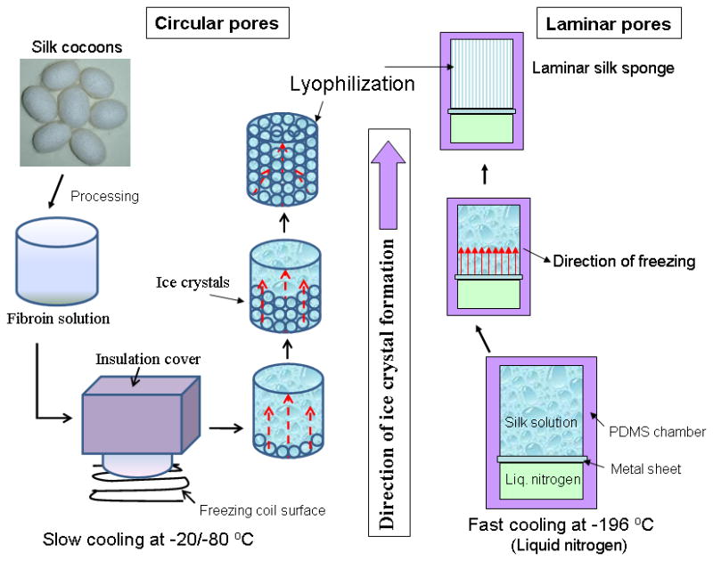
Schematic showing the affect of temperature on pore shape and alignment within 3D silk scaffolds using directional freezing.
This new method of horizontally freezing polymers in the specially designed PDMS chamber has advantages compared to conventional methods of freezing vertically from bottom using tubes/cylinders, due to the linearly arranged channels/pores throughout the length.24, 28, 29, 39 Achieving homogeneity is important in tissue engineering as heterogeneity in pores/direction within scaffold structures may affect tissue mechanics, regeneration and cellular responses such as migration. Further, there is no limitation to the length and height of scaffolds that can be fabricated using this method, while there is limitation to the maximum width of scaffolds that can be fabricated (~4 cm) due to the freezing front where the temperature drops rapidly and effective laminar ice crystal channels are lost beyond this distance.
Scaffold morphology and porosity
Directional freezing has been reported in studies with sol-gel synthesis to produce aligned fibers, silica micro-honeycombs and other aligned ceramics.21–23, 32 In the present study silk in aqueous was used to form aligned 3D structures. As observed from SEM and confocal images, linearly arranged pore channels formed (Figure 1g, h, 3, 4). These laminar channels are negative replicas of the ice crystals formed during the freezing process due to phase separation and can be explained similar to previous silica systems.21, 22, 32 Freezing of silk causes constitutional super cooling at the interphase, forming ice crystals due to Mullins-Sekerka instability, where the silk biopolymer is concentrated between the freezing water crystals resulting in thin wall formation (Figure 4b, d).24, 40, 41 Upon freeze drying, ice sublimes leaving behind laminar walls within the porous silk scaffold. Further, the laminar architecture was devoid of heterogeneity and is continuous without separated porous zones (random pores, laminar pores) (Figure 4, 5). Rapid freezing is an important factor in forming laminar channels as slow cooling at temperatures of −20/−80°C will allow more time for maximum ice growth, resulting in spherical crystals leading to circular pores as opposed to aligned pores (Figure 2).4
Figure 3.
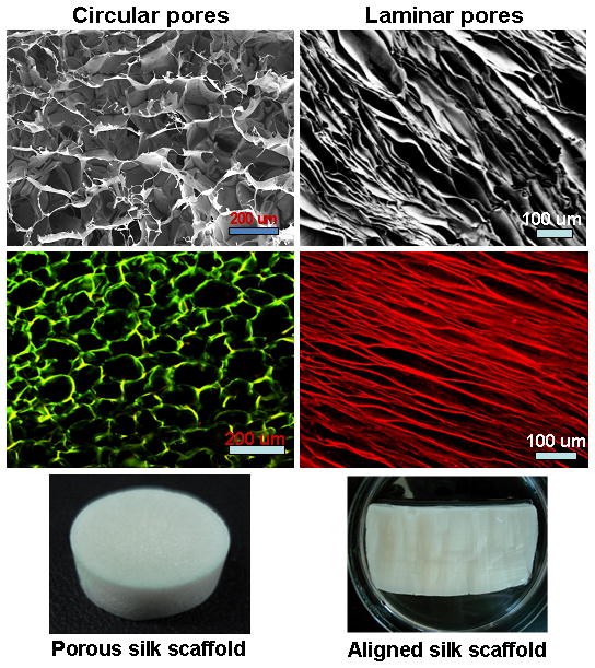
Scanning electron microscopic and confocal images showing 3D scaffolds with circular and laminar pores. Circular and laminar pores were fabricated at −20°C and −196°C, respectively, using directional freezing.
Figure 4.
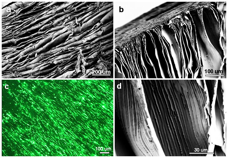
(a–b) Scanning electron microscopy images show aligned laminar channels within 3D silk scaffolds; (c) hMSC alignment and survival on silk scaffolds (Live-Dead staining); and (d) magnified image of thin scaffold wall with linear inner patterns.
Figure 5.
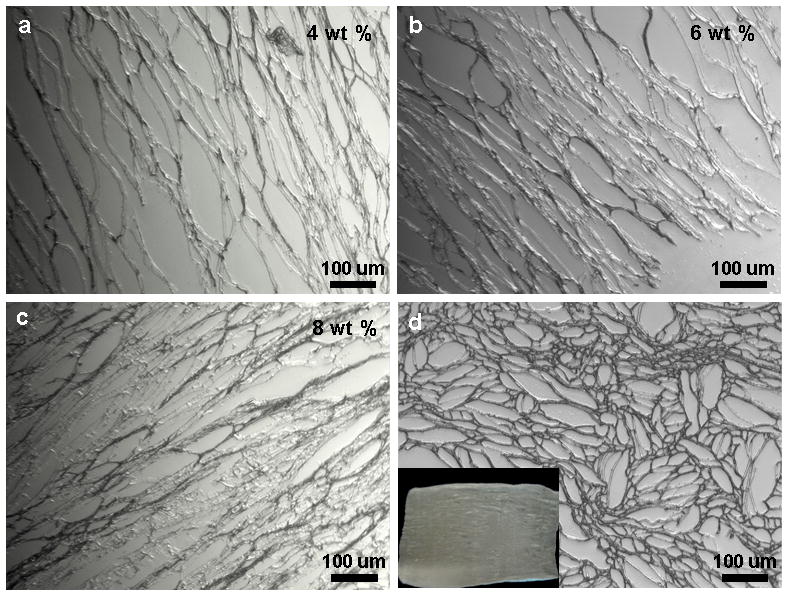
Histological sections show laminar scaffolds of (a–c) various wt% silk concentrations having different pore widths; and (d) scaffold transverse section with open ended pore channels of different sizes. Scale bar 100 microns.
The spacing between lamina (laminar channel/pore sizes) can be adjusted by changing protein concentration. Pore size/silk lamina distance (width) increased with a decrease in polymer concentration (Figure 5). Larger channels in the range of 50–120 μm were observed for 4 wt% silk, compared to 30–50 μm and 10–30 μm for 6 and 8 wt% silk, respectively. Further, pores/lamina were highly interconnected. Similarly, using silk protein of 4, 6 and 8 wt%, porosity in the range of 91 ± 04, 86 ± 07 and 79 ± 09 % was obtained, respectively (Figure 6b). It is also possible to vary pore lamina distance to obtain larger pores by varying the freezing rate.28 This is important for potential applications such as filtration or selective infiltration of cells, where the pore size needs to be controlled. Transverse sections of the scaffolds show circular openings of varied sizes in the range of 20–100 μm, due to presence of longitudinal cylindrical channels formed as a result of freezing (Figure 5d). In previous studies using 3D scaffolds, the importance of higher porosity and interconnectivity over unconnected/closed larger pores effected cellular migration and proliferation.4
Figure 6.
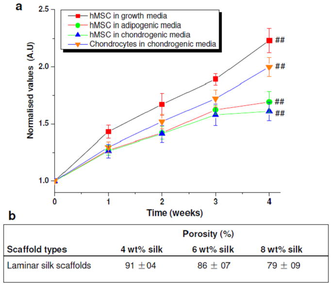
(a) Cell proliferation showing normalized values of cell growth within laminar silk scaffolds over 4 weeks; (b) Porosity % for different wt % laminar silk scaffolds. Data represents mean ± standard deviation (n=4), where ##p ≤ 0.01.
Mechanical properties
A 3D scaffold intended for biological/tissue engineering needs to undergo various physiological stresses and shear forces. Silk scaffolds fabricated using directional freezing showed varied compressive modulus and strength directly proportional to the content of silk (Figure 7). Interestingly, based on silk scaffold alignment, compressive forces needed to deform scaffold varied, demonstrating the anisotropic morphological features reflected in the mechanical properties (Figure 7). Scaffolds with lamina/channels parallel (0°) to the compressive force showed higher mechanical values when compared to scaffolds with lamina/channels perpendicular (90°). Compressive modulus in the range of ~50, ~88, ~ 250 kPa were observed for laminar scaffolds prepared from 4, 6 and 8 wt% silk, respectively, oriented parallel to the applied compressive force (##p ≤ 0.01). Lower compressive modulus values of ~5.5, ~23, ~36 kPa for laminar scaffolds prepared from 4, 6 and 8 wt% silk respectively were observed when the samples were placed perpendicular to the applied force (##p ≤ 0.01).
Figure 7.
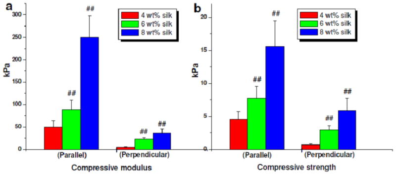
Mechanical properties of laminar silk scaffolds of different silk wt % concentrations. Data represents mean ± standard deviation (n=6), where ##p ≤ 0.01.
Similarly, for assessments of compressive strength, scaffolds prepared from 4, 6 and 8 wt% silk and oriented parallel had values of ~5, ~8, and ~16 kPa, respectively (##p ≤ 0.01). These values decreased to ~1, ~3, and ~6 kPa, respectively, when placed perpendicular (##p ≤ 0.01). Higher compressive modulus values for scaffolds with lamina/channels parallel to the applied force can be attributed to the resistance offered by virtue of the parallel structures.
Cell survival, alignment and differentiation
Cellular compatibility and survival in a construct is vital for its use as a graft material in biomedical applications. Silk by virtue of its inherent advantages, including aqueous and ambient processing, high strength, biocompatibility, biodegradability with low inflammatory and immunogenic responses was the choice in the present study.4, 6, 33, 34, 36, 42 hMSCs and hCHs were seeded on the lamellar scaffold systems and cultured for 4 weeks (Figure 6a). hMSCs proliferated ~120% to their initial seeding in normal growth medium within 4 weeks (##p ≤ 0.01) and primary hCHs showed ~80% increase when cultured in chondrogenic medium (##p ≤ 0.01). In differentiation medium hMSCs proliferated both in adipogenic and chondrogenic medium with an increase of 50% cell numbers after 4 weeks (##p ≤ 0.01), a lower response as expected upon differentiation. Cells aligned within the laminar channels as observed after actin and nuclei staining (Figure 1g, h).
Differentiation of hMSCs was further confirmed by staining harvested samples after 4 weeks of culture (Figure 8). Adipogenic differentiation was marked by deposition of oil droplets stained by Oil-Red O.43 Similarly, deep blue staining was observed following Alcian blue staining, suggesting sGAG deposition.37, 38 The results suggest supportive scaffolds towards various lineages in the presence of differentiation media. Further, from the stained images for sGAG and oil droplets, an orientation response pattern was evident (Figure 8). This is important in tissue engineering, where cells align the deposited ECM akin to the native architecture and related to specific tissue grafting needs.
Figure 8.
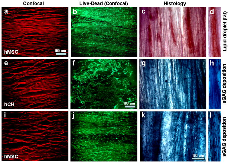
Confocal and histology sections showing cell and extracellular matrix (ECM) alignment and deposition within laminar silk scaffolds. Where, (a–d) hMSCs differentiated towards adipogenesis with deposition of oil droplets; (e–h) hCH growth and proliferation in chondrogenic media with deposition of sGAG; and (i–l) hMSCs differentiated towards chondrogenesis with deposition of sGAG. (d, h, l) represent transverse section of scaffold with ECM deposition. Scale bar 100 microns.
Primary hCHs were used as they are difficult to align and maintain polygonal shape. Moreover, it is undesirable for hCHs to attained spindle shaped morphology similar to fibroblasts, a possible sign of dedifferentiation. The hCHs attained a degree of alignment within laminar scaffolds and also maintained their native polygonal architecture (Figure 8f). As a result, the deposited sGAG was aligned as well (Figure 8g). This may help to generate mature cartilage-like tissue in areas where some alignment is required, such as at tissue interfaces.
In vivo response to laminar scaffolds
To evaluate and understand material immune response and implant integration, laminar scaffolds were implanted subcutaneously in the back of mice and were retrieved after 1 and 4 weeks (Figure 9). Following retrieval and H&E staining after 1 week, intermittent numbers of immune cells were observed surrounding the implants.34, 44 Cell sheets, 9–12 layers, consisting of macrophages and fibroblasts were observed and macrophages were restricted to the immediate host-implant interface (Figure 9d). The interface layer was superimposed by oriented fibroblasts, fewer lymphocytes, and devoid of giant cells. Silk degradation was not visible over the time frame of study. These results are in agreement with previous published reports showing intermittent adhesion of immuno-competent cells to de-gummed pure silk fibroin in vitro.44 At the end of 4 weeks, retrieved scaffold samples showed fewer inflammatory cells surrounding the implants (Figure 9e). Similar results of immune compatibility of pure silk has already been demonstrated in vivo, showing lower inflammatory response over time when compared to collagen and polylactic acid (PLA).34 Further studies with silk non-woven mats implanted subcutaneously in rats induced only a weak foreign body response and no subsequent fibrosis with little upregulation of inflammatory pathways at the implantation site and further no invasion by lymphocytes after six months in vivo.35 Close integration of the implanted scaffolds and mice tissue in the present study was observed. Further, during harvest after 4 weeks, dense tissue ingrowths with high vascularization with the implants were observed (Figure 9c).
Figure 9.
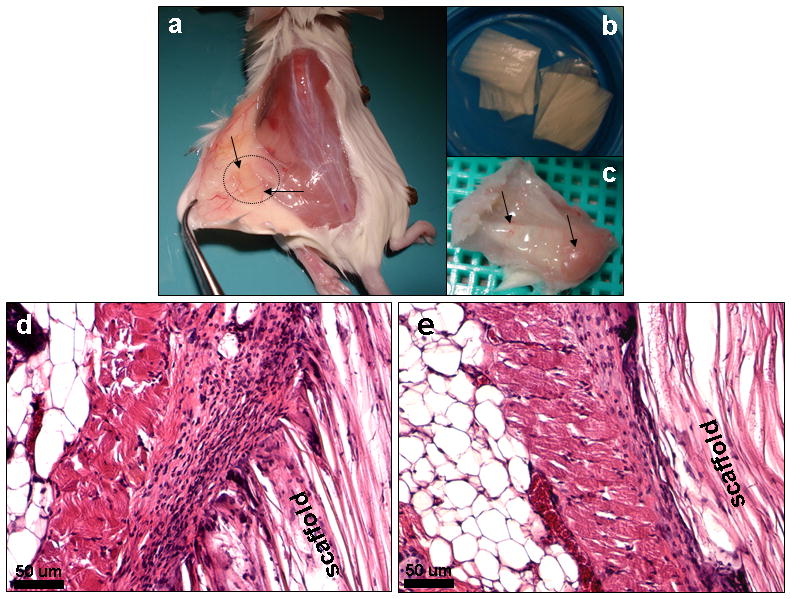
Histological images showing in vivo immunological response of fabricated laminar silk scaffolds in mice (a) after 1 week (d) and 4 weeks (e). Stained with H and E. Microscopic images (b) show laminar scaffolds implanted subcutaneously in mice and vascularization of implants (c) after 4 weeks. Scale bar 50 microns.
Conclusions
A relatively simple method to generate homogeneously aligned silk 3D matrices with control of porosity and compressive strength using a direction ice freezing method was demonstrated. The proposed method can further be applied to a wide range of water soluble/dispersed polymers and has the potential to produce complex, multicomponent aligned structures for various biomaterial and tissue engineering applications. These morphological features are specifically important in tissue regeneration, where 3D porous matrices capable of aligning biological cells are useful to mimic native tissue hierarchy and function. The developed 3D aligned scaffold systems provide insight on the role of alignment on mechanical properties. A combination of matrix alignment and surface porosity favored hCH and hMSC proliferation and differentiation.
Acknowledgments
We thank the NIH (EY020856 P41 EB002520-05) and the AFOSR (FA9550-10-1-01720 for support of these studies.
References
- 1.Langer R, Vacanti JP. Tissue engineering. Science. 1993;260:920. doi: 10.1126/science.8493529. [DOI] [PubMed] [Google Scholar]
- 2.Place ES, Evans ND, Stevens MM. Complexity in biomaterials for tissue engineering. Nature Mater. 2009;8:457. doi: 10.1038/nmat2441. [DOI] [PubMed] [Google Scholar]
- 3.Nerurkar NL, Baker BM, Sen S, Wible EE, Elliott DM, Mauck RL. Nanofibrous biologic laminates replicate the form and function of the annulus fibrosus. Nat Mater. 2009;8:986. doi: 10.1038/nmat2558. [DOI] [PMC free article] [PubMed] [Google Scholar]
- 4.Mandal BB, Kundu SC. Cell proliferation and migration in 3D silk fibroin scaffolds. Biomaterials. 2009;30:2956. doi: 10.1016/j.biomaterials.2009.02.006. [DOI] [PubMed] [Google Scholar]
- 5.Wang Y, Blasioli DJ, Kim HJ, Kim HS, Kaplan DL. Cartilage tissue engineering with silk scaffolds and human articular chondrocytes. Biomaterials. 2006;27:4434. doi: 10.1016/j.biomaterials.2006.03.050. [DOI] [PubMed] [Google Scholar]
- 6.Wang Y, Kim HJ, Vunjak-Novakovic G, Kaplan DL. Stem cell-based tissue engineering with silk biomaterials. Biomaterials. 2006;27:6064. doi: 10.1016/j.biomaterials.2006.07.008. [DOI] [PubMed] [Google Scholar]
- 7.Vepari C, Kaplan DL. Silk as a biomaterial. Prog Polym Sci. 2007;32:991. doi: 10.1016/j.progpolymsci.2007.05.013. [DOI] [PMC free article] [PubMed] [Google Scholar]
- 8.Meinel L, Hofmann S, Karageorgiou V, Zichner L, Langer R, Vunjak-Novakovic G, Kaplan DL. Engineering cartilage-like tissue using human mesenchymal stem cells and silk protein scaffolds. Biotechnol Bioeng. 2004;88:379. doi: 10.1002/bit.20252. [DOI] [PubMed] [Google Scholar]
- 9.Altman GH, Diaz F, Jakuba C, Calabro T, Horan RL, Chen J, Lu H, Richmond J, Kaplan DL. Silk based biomaterials. Biomaterials. 2003;24:401. doi: 10.1016/s0142-9612(02)00353-8. [DOI] [PubMed] [Google Scholar]
- 10.Mikos AG, Temenoff JS. Formation of highly porous biodegradable scaffolds for tissue engineering. Electron J Biotechnol. 2000;3:114. [Google Scholar]
- 11.Lutolf MP, Weber FE, Schmoekel HG, Schense JC, Kohler T, Muller R, Hubbell JA. Repair of bone defects using synthetic mimetics of collagenous extracellular matrices. Nat Biotechnol. 2003;21:513. doi: 10.1038/nbt818. [DOI] [PubMed] [Google Scholar]
- 12.Li WJ, Laurencin CT, Caterson EJ, Tuan RS, Ko FK. Electrospun nanofibrous structure: A novel scaffold for tissue engineering. J Biomed Mater Res. 2002;60:613. doi: 10.1002/jbm.10167. [DOI] [PubMed] [Google Scholar]
- 13.Mooney DJ, Baldwin DF, Suh NP, Vacanti JP, Langer R. Novel approach to fabricate porous sponges of poly (D, L-lactic-coglycolic acid) without the use of organic solvents. Biomaterials. 1996;17:1417. doi: 10.1016/0142-9612(96)87284-x. [DOI] [PubMed] [Google Scholar]
- 14.Sherwood JK, Riley SL, Palazzolo R, Brown SC, Monkhouse DC, Coates M, Griffith LG, Landeen LK, Ratcliffe A. A three dimensional osteochondral composite scaffold for articular cartilage repair. Biomaterials. 2002;23:4739. doi: 10.1016/s0142-9612(02)00223-5. [DOI] [PubMed] [Google Scholar]
- 15.Ma PX, Zhang RY. Microtubular architecture of biodegradable polymer scaffolds. J Biomed Mater Res. 2001;56:469. doi: 10.1002/1097-4636(20010915)56:4<469::aid-jbm1118>3.0.co;2-h. [DOI] [PubMed] [Google Scholar]
- 16.Patist CM, Mulder MB, Gautier SE, Maquet V, Jeorome R, Oudega M. Freeze dried poly (D, L-lactic acid) macroporous guidance scaffolds impregnated with brain-derived neurotrophic factor in the transected adult rat thoracic spinal cord. Biomaterials. 2004;25:1569. doi: 10.1016/s0142-9612(03)00503-9. [DOI] [PubMed] [Google Scholar]
- 17.McCann JT, Marquez M, Xia Y. Highly porous fibers by electrospinning into a cryogenic liquid. J Am Chem Soc. 2006;128:1436. doi: 10.1021/ja056810y. [DOI] [PubMed] [Google Scholar]
- 18.Li M, Wu C, Lu S, Yan H, Huang D, Ye H. Study on porous silk fibroin materials. II. Preparation and characteristics of spongy porous silk fibroin materials. J Appl Polym Sci. 2001;79:2192. [Google Scholar]
- 19.Kenar H, Kose GT, Toner M, Kaplan DL, Hasirci V. A 3D aligned microfibrous myocardial tissue construct cultured under transient perfusion. Biomaterials. 2011;32:5320. doi: 10.1016/j.biomaterials.2011.04.025. [DOI] [PMC free article] [PubMed] [Google Scholar]
- 20.Bhardwaj N, Kundu SC. Electrospinning: a fascinating fiber fabrication technique. Biotechnol Adv. 2010;28:325. doi: 10.1016/j.biotechadv.2010.01.004. [DOI] [PubMed] [Google Scholar]
- 21.Mahler W, Bechtold MF. Freeze-formed silica fibres. Nature. 1980;285:27. [Google Scholar]
- 22.Mukai SR, Nishihara H, Tamon H. Formation of monolithic silica gel microhoneycombs (SMHs) using pseudosteady state growth of microstructural ice crystals. Chem Commun. 2004;7:874. doi: 10.1039/b316597c. [DOI] [PubMed] [Google Scholar]
- 23.Fukasawa T, Ando M, Ohji T, Kanzaki S. Synthesis of porous ceramics with complex pore structure by freeze-dry processing. J Am Ceram Soc. 2001;84:230. [Google Scholar]
- 24.Zhang H, Hussain I, Brust M, Butler MF, Rannard SP, Cooper AI. Aligned two-and three-dimensional structures by directional freezing of polymers and nanoparticles. Nat Mater. 2005;4:787. doi: 10.1038/nmat1487. [DOI] [PubMed] [Google Scholar]
- 25.Ferrer ML, Esquembre R, Ortega I, Mateo CR, del Monte F. Freezing of binary colloidal systems for the formation of hierarchy assemblies. Chem Mater. 2006;18:554. [Google Scholar]
- 26.Zhang H, Cooper AI. Aligned porous structures by directional freezing. Adv Mater. 2007;19:1529. [Google Scholar]
- 27.Yang F, Qu X, Cui W, Bei J, Yu F, Lu S, Wang S. Manufacturing and morphology structure of polylactide-type microtubules orientation-structured scaffolds. Biomaterials. 2006;27:4923. doi: 10.1016/j.biomaterials.2006.05.028. [DOI] [PubMed] [Google Scholar]
- 28.Deville S, Saiz E, Tomsia AP. Freeze casting of hydroxyapatite scaffolds for bone tissue engineering. Biomaterials. 2006;27:5480. doi: 10.1016/j.biomaterials.2006.06.028. [DOI] [PubMed] [Google Scholar]
- 29.Deville S, Saiz E, Nalla RK, Tomsia AP. Freezing as a Path to Build Complex Composites. Science. 2006;311:515. doi: 10.1126/science.1120937. [DOI] [PubMed] [Google Scholar]
- 30.Deville S, Saiz E, Tomsia AP. Ice-templated porous alumina structures. Acta Mater. 2007;55:1965. [Google Scholar]
- 31.Gutierrez MC, Jobbagy M, Rapun N, Ferrer ML, del Monte F. A biocompatible bottom-up route for the preparation of hierarchical biohybrid materials. Adv Mater. 2006;18:1137. [Google Scholar]
- 32.Mukai SR, Nishihara H, Shichi S, Tamon H. Preparation of porous TiO2 cryogel fibers through unidirectional freezing of hydrogel followed by freeze-drying. Chem Mater. 2004;16:4987. [Google Scholar]
- 33.Altman GH, Horan RL, Lu HH, Moreau J, Martin I, Richmond JC, Kaplan DL. Silk matrix for tissue engineered anterior cruciate ligaments. Biomaterials. 2002;23:4131. doi: 10.1016/s0142-9612(02)00156-4. [DOI] [PubMed] [Google Scholar]
- 34.Meinel L, Hofmann S, Karageorgiou V, Kirker-Head C, McCool J, Gronowicz G, Zichner L, Langer R, Vunjak-Novakovic G, Kaplan DL. The inflammatory responses to silk films in vitro and in vivo. Biomaterials. 2005;26:147. doi: 10.1016/j.biomaterials.2004.02.047. [DOI] [PubMed] [Google Scholar]
- 35.Dal-Pra I, Freddi G, Minic J, Chiarini A, Armato U. De novo engineering of reticular connective tissue in vivo by silk fibroin nonwoven materials. Biomaterials. 2005;26:1987. doi: 10.1016/j.biomaterials.2004.06.036. [DOI] [PubMed] [Google Scholar]
- 36.Wang Y, Rudym DD, Walsh A, Abrahamsen L, Kim HJ, Kim HS, Kirker-Head C, Kaplan DL. In vivo degradation of three-dimensional silk fibroin scaffolds. Biomaterials. 2008;29:3415. doi: 10.1016/j.biomaterials.2008.05.002. [DOI] [PMC free article] [PubMed] [Google Scholar]
- 37.Mandal BB, Park SH, Gil ES, Kaplan DL. Stem cell based meniscus tissue engineering. Tissue Eng A. 2011;17:2749. doi: 10.1089/ten.tea.2011.0031. [DOI] [PMC free article] [PubMed] [Google Scholar]
- 38.Mandal BB, Park SH, Gil ES, Kaplan DL. Multilayered silk scaffolds for meniscus tissue engineering. Biomaterials. 2011;32:639. doi: 10.1016/j.biomaterials.2010.08.115. [DOI] [PMC free article] [PubMed] [Google Scholar]
- 39.Wu X, Liu Y, Li X, Wen P, Zhang Y, Long Y, Wang X, Guo Y, Xing F, Gao J. Preparation of aligned porous gelatin scaffolds by unidirectional freeze-drying method. Acta Biomater. 2010;6:1167. doi: 10.1016/j.actbio.2009.08.041. [DOI] [PubMed] [Google Scholar]
- 40.Butler MF. Instability formation and directional dendritic growth of ice studied by optical interferometry. Cryst Growth Des. 2001;1:213. [Google Scholar]
- 41.Butler MF. Freeze concentration of solutes at the ice/solution interface studied by optical interferometry. Cryst Growth Des. 2002;2:541. [Google Scholar]
- 42.Omenetto FG, Kaplan DL. New opportunities for an ancient material. Science. 2010;329:528. doi: 10.1126/science.1188936. [DOI] [PMC free article] [PubMed] [Google Scholar]
- 43.Mandal BB, Kundu SC. Osteogenic and adipogenic differentiation of rat bone marrow cells on mulberry and non-mulberry silk gland fibroin 3D scaffolds. Biomaterials. 2009;30:5019. doi: 10.1016/j.biomaterials.2009.05.064. [DOI] [PubMed] [Google Scholar]
- 44.Santin M, Motta A, Freddi G, Cannas M. In vitro evaluation of the inflammatory potential of the silk fibroin. J Biomed Mater Res. 1999;46:382. doi: 10.1002/(sici)1097-4636(19990905)46:3<382::aid-jbm11>3.0.co;2-r. [DOI] [PubMed] [Google Scholar]


