

Abstract
Histone posttranslational modifications (PTMs) play a pivotal role in regulating the dynamics and function of chromatin. Supported by an increasing body of literature, histone PTMs such as methylation and acetylation function together in the context of a “histone code,” which is read, or interpreted, by effector proteins that then drive a functional output in chromatin (e.g., gene transcription). A growing number of domains that interact with histones and/or their PTMs have been identified. While significant advances have been made in our understanding of how these domains interact with histones, a wide number of putative histone-binding motifs have yet to be characterized, and undoubtedly, novel domains will continue to be discovered. In this chapter, we provide a detailed method for the construction of combinatorially modified histone peptides, microarray fabrication using these peptides, and methods to characterize the interaction of effector proteins, antibodies, and the substrate specificity of histone-modifying enzymes. We discuss these methods in the context of other available technologies and provide a user-friendly approach to enable the exploration of histone–protein–enzyme interactions and function.
1. INTRODUCTION
More than 15 years ago, Allis and Schreiber independently identified the molecular link between histone posttranslational modifications (PTMs) and transcriptional regulation (Brownell et al., 1996; Taunton, Hassig, & Schreiber, 1996). Since then, a significant effort has been placed on the identification and biological characterization of histone PTMs, which function in DNA-templated processes such as transcription, recombination, and DNA repair (Kouzarides, 2007). The N- and C-terminal “tails” of the four core histone proteins are rich in amino acids that are known sites of PTM (Fig. 6.1). These PTMs include, but are not limited to, methylation, acetylation, and ubiquitination of lysine, and phosphorylation of serine and threonine. How the myriad of known histone PTMs function has remained a fundamental question in modern biology.
Figure 6.1.

A representation of select posttranslational modifications (PTMs) on human histones. Depicted are the PTMs that are most amenable for peptide synthesis, such as acetylation (ac), methylation (me), and phosphorylation (P). *Histone lysine methylation occurs in three forms (mono-, di-, and trimethylation), as does arginine methylation (monomethylation, symmetric, and asymmetric dimethylation).
It is thought that histone PTMs function to regulate the diverse activities associated with chromatin (Gardner, Allis, & Strahl, 2011; Kornberg & Lorch, 1999; Kouzarides, 2007). The “histone code” hypothesis, formally introduced just over a decade ago, suggests that histone PTMs function in a combinatorial fashion to regulate chromatin structure and function (Jenuwein & Allis, 2001; Strahl & Allis, 2000). We now know that histone PTMs such as lysine acetylation can directly alter the physical structure of chromatin by charge neutralization (Shogren-Knaak et al., 2006), and PTMs can also serve as binding sites for effector proteins that contain one or more well-characterized protein folds (Taverna, Li, Ruthenburg, Allis, & Patel, 2007). For example, methyllysine can be recognized by motifs like chromodomains and plant homeodomains (PHD), while acetyllysine can be recognized by bromodomains. Increasing evidence is emerging to support the “histone code” hypothesis, in the context of both effector protein binding and antibody recognition (Bock et al., 2011; Fuchs & Strahl, 2011; Garske et al., 2010), and more recently on the multivalent engagement of effector proteins with chromatin through linked recognition domains (Allis & Muir, 2011; Ruthenburg, Li, Patel, & Allis, 2007). A notable example of the latter is the recent finding that the paired bromodomain and PHD finger of the BPTF subunit of the NURF chromatin-remodeling complex simultaneously engage nucleosomes bearing H4 lysine 16 acetylation (H4K16ac) and H3 lysine 4 trimethylation (H3K4me3), respectively (Ruthenburg et al., 2011).
In the past few years, a number of successful strategies have been used to discover and characterize proteins (and their domains) that recognize histones and histone PTMs. These range from high-throughput batch screening of purified proteins using large peptide libraries on beads (Garske et al., 2010), discovery-based approaches utilizing stable isotope labeling with amino acids in culture (SILAC) combined with peptide and/or nucleosomal pull-downs (Vermeulen et al., 2011), and a number of peptide microarray-based approaches utilizing purified recombinant proteins (Bock et al., 2011; Bua et al., 2009; Nady, Min, Kareta, Chedin, & Arrowsmith, 2008). Bead-based approaches have significant advantages in the large library size that can be created but require labor-intensive screening to identify “hits.” SILAC-based approaches offer tremendous potential to identify novel histone-interacting proteins and protein complexes. However, they do not report on the domain, or protein from within a complex, that binds to the peptide or nucleosome used in the pull-down. Peptide microarrays provide an extremely rapid and robust method for measuring binding to a large number of peptide substrates, although the development of the peptide library itself may be time intensive. While each of the different approaches to identify and characterize histone-interacting proteins have their advantages and disadvantages, it is clear that these approaches are valuable ways to characterize histone interactions and are fundamental to advancing the chromatin field.
Here, we describe a microarray approach using high-purity biotinylated peptides spotted onto streptavidin-coated glass slides. We describe the peptide synthesis and the microarray fabrication as well as the methodology for using these microarrays to probe the binding of not only histone-binding proteins but also PTM-specific antibodies and histone-modifying enzymes.
2. HISTONE PEPTIDE LIBRARY
The generation of any peptide microarray begins at the number and type of peptides one needs for a given project. For example, a large number of biotinylated histone peptides bearing one to several histone PTMs are now commercially available; thus production of high-density peptide microarrays is feasible without the need for peptide synthesis. For some projects, however, certain histone PTMs (or combinations thereof) may not be available. While custom-made peptides can be purchased from a variety of commercial vendors, commercial synthesis of peptides can be very expensive and the quality of such peptides is often variable. We recommend that the quality of any purchased peptide be verified independently by mass spectrometry and analytical reversed-phase high-performance liquid chromatography (RP-HPLC) (see Section 2.3). Alternatively, performing peptide synthesis de novo, using easily obtainable peptide synthesis equipment and reagents, can be a cost-saving measure to produce significant quantities of high-quality peptides when the needed peptides are not readily available or very expensive. Moreover, the synthesized peptides can be used for biophysical approaches like isothermal titration calorimetry (ITC) or surface plasmon resonance (SPR). Below, we summarize our recent experience creating a focused library of biotinylated histone peptides containing multiple PTMs (Fuchs, Krajewski, Baker, Miller, & Strahl, 2011). In this study, a 110-peptide library was generated within a few months using a PS3 peptide synthesizer (Protein Technologies, Inc.), which requires little training and is easy to use. Subsequently, this library was considerably expanded using the more sophisticated Symphony multiple peptide synthesizer (Protein Technologies, Inc.).
A variety of books and publications on the general procedures of fluorenylmethyloxycarbonyl (Fmoc)-based solid phase peptide synthesis (SPPS) have already been published (Abelson, Simon, & Fields, 1997; Amblard, Fehrentz, Martinez, & Subra, 2006; Chan & White, 2000; Coin, Beyermann, & Bienert, 2007; Howl, 2005). Therefore, this chapter focuses primarily on the synthesis of biotinylated histone peptides containing one or more PTMs. The design strategies are highlighted further below.
2.1. Peptide library design
The biological question one is trying to answer dictates the design of the peptide library. For example, in order to identify a region of a histone or a histone PTM that is important for the association of a poorly characterized effector protein, one would likely want to generate a simple histone peptide library containing only unmodified peptides and histone peptides carrying one PTM. However, if an associated PTM for an effector protein is already known, one would want to develop an expanded peptide library that includes additional modifications surrounding the site of modification the effector protein binds to (in order to determine how neighboring PTMs influence the binding of the effector protein that is under investigation). Below we expand upon some of the important factors that should be considered when designing a histone peptide library for binding or enzymatic studies.
2.1.1 Position of the biotin tag
Adding D-biotin at either the N- or C-terminus of the peptide is required for immobilization onto streptavidin-coated slides. For peptides representing the N-terminus of a histone tail, a biotin tag is incorporated at the C-terminus of the sequence. For peptides representing the C-terminus of a histone tail, the biotin tag is incorporated at N-terminus of the sequence. This placement is important, as it mimics the manner in which the histone “tails” are displayed from the nucleosome core. For peptides representing regions within the core histone fold, we typically incorporate the biotin tag at the C-terminus of the sequence and acetylate the N-terminal amine group (to mimic a more natural N-terminal amide bond). If a functionally important region of a histone in the peptide sequence is in close proximity to the biotinylated terminus of the peptide, a short polyethylene glycol (PEG) linker (~20 Å long, see Fig. 6.2A) is added to separate the histone peptide sequence away from the D-biotin tag and the streptavidin surface.
Figure 6.2.

Chemical derivatives used for the synthesis of modified histone tails suitable for arraying. (A) N- and C-terminal biotin tags with PEG linkers. (B) Derivatives used for PTM incorporation.
2.1.2 Length of the peptide sequence
Peptide synthesis on a PS3 (or similar peptide synthesizer) followed by RP-HPLC purification and analysis of each peptide (MS and analytical RP-HPLC) comfortably allows for the synthesis of peptides surpassing 20 amino acids in length. This is considerably longer than what is achievable by other peptide synthesis technologies, such as synthetic peptide microarrays on membrane support (SPOT synthesis), typically between 10 and 15 amino acids in length (Hilpert, Winkler & Hancock, 2007; Nady et al., 2008). We find that histone peptides containing 20–25 residues can be easily synthesized and purified with ≥90% purity by RP-HPLC. Synthesis of longer sequences (30–40 residues) is also possible but is more time consuming and usually complicates peptide purification. In general, histone tail sequences are usually water soluble, so longer peptides are easier to generate and purify. However, for peptides representing internal sequences, such as the histone fold region, synthesizing shorter peptides is recommended due to potential problems with peptide solubility.
We prefer to synthesize the longest histone tail peptides possible for several reasons. (1) Longer histone peptides allow us to experimentally test the importance of a greater number of PTM combinations. (2) There is experimental evidence that long-range interactions are biologically meaningful for the binding of certain histone-modifying enzymes and/or effector proteins. For example, the histone demethylase JMJD2A binds H3K4me3 and demethylates lysines 9 and 36 on histone H3 (Huang, Fang, Bedford, Zhang, & Xu, 2006; Klose et al., 2006; Whetstine et al., 2006). (3) Having peptide-based libraries with longer sequences carries a considerable advantage in downstream projects and applications. For several effector proteins, we have now observed much higher affinities by ITC and fluorescence polarization (FP) using longer peptides than the values published using shorter peptide sequences carrying the same PTMs (Rothbart et al., unpublished data).
2.1.3 Scale of peptide synthesis
A synthetic scale of between 10 and 25 μmol for each peptide is sufficient to yield at least 5 mg of purified peptide, even if the synthesis and/or purification is difficult. This amount is sufficient to print hundreds of microarrays and have enough peptide remaining to perform downstream biophysical experiments to further characterize binding interactions.
2.2. Peptide synthesis
Equipment and materials
Peptide synthesizer (Symphony or PS-3 synthesizers from Protein Technologies, Inc. or equivalent)
Freeze-dryer with condenser temperature < −70 °C (VirTis BTK2-XL, BTK4-ZL or equivalent) and several 600 mL vacuum flasks
Explosion-proof centrifuge that can accommodate 50 mL tubes
2.5 mL polypropylene syringes with frit (Torviq)
50 mL polypropylene centrifuge tubes
Resins: Biotin-PEG NovaTag™ resin (EMD), Rink amide NovaPeg resin (EMD), H-Rink amide ChemMatrix® resin (PCAS BioMatrix), 2-Chlorotrityl chloride resin (EMD)
Standard Fmoc derivatives of the 20 coded L-amino acids: Fmoc-Ala-OH, Fmoc-Arg(Pbf)-OH, Fmoc-Asn(Trt)-OH, Fmoc-Asp (OtBu)-OH, Fmoc-Cys(Trt)-OH, Fmoc-Gln(Trt)-OH, Fmoc-Glu (OtBu)-OH, Fmoc-Gly-OH, Fmoc-His(Trt)-OH, Fmoc-Ile-OH, Fmoc-Leu-OH, Fmoc-Lys(Boc)-OH, Fmoc-Met-OH, Fmoc-Phe-OH, Fmoc-Pro-OH, Fmoc-Ser(tBu)-OH, Fmoc-Thr(tBu)-OH, Fmoc-Trp(Boc)-OH, Fmoc-Val-OH, Fmoc-Tyr(tBu)-OH can be purchased prepacked in vials from a synthesizer vendor or numerous commercial suppliers.
Fmoc derivatives of PTM-modified amino acids and other nonstandard derivatives: Fmoc-Asp(Mpe)-OH, Fmoc-Arg(Me,Pbf)-OH, Fmoc-Arg(Me2a,Pbf)-OH, Fmoc-Arg(Me2s,Boc2)-OH, 1 Fmoc-Cit(Pbf)-OH, Fmoc-Lys(biotin)-OH, Fmoc-Lys(Me,Boc)-OH, Fmoc-Lys(Me2)-OH·HCl, Fmoc-Lys(Me3Cl)-OH, Fmoc-Ser(PHO3Bzl)-OH, Fmoc-Thr(PHO3Bzl)-OH), and coupling reagents (N,N′-diisopropylcarbodiimide (DIC), O-(7-azabenzotriazol-1-yl)-N,N,N′, N′-tetramethyluronium hexafluorophosphate (HATU), and 1-hydroxy-7-azabenzotriazole (HOAt)) can be purchased from a number of commercial vendors.
Solvents and reagents: N,N-dimethylformamide (DMF), N-methyl-2-pyrollidone (NMP), dichloromethane (DCM), diethyl ether (anhydrous), piperidine, N,N-diisopropylethylamine (DIEA), 4-methylmorpholine, trifluorocaetic acid (TFA) can be purchased from numerous commercial suppliers.
-
A ninhydrin test kit can be purchased from AnaSpec. Note: Ninhydrin test reagents are toxic and corrosive and must be handled with care.
All canonical Fmoc-amino acids and Fmoc-Lys(Ac)-OH were coupled using automated Fmoc SPPS. All other modified amino acid derivatives were coupled manually as described below.
The peptide PTMs represented in our peptide library and Fmoc derivatives used to introduce PTMs are listed in Table 6.1 and Fig. 6.2B.
Table 6.1.
PTM derivatives and coupling methods for histone peptide synthesis
| Modified amino acid | Fmoc-protected derivative | Coupling method |
|---|---|---|
| Lys(Ac) | Fmoc-Lys(Ac)-OH | Standard (protocol A2 with double coupling) |
| Lys(Me) | Fmoc-Lys(Me,Boc)-OH | Manual (protocol B) |
| Lys(Me2) | Fmoc-Lys(Me2)-OH·HCl | Manual (protocol B)a |
| Lys(Me3) | Fmoc-Lys(Me3Cl)-OH | Manual (protocol B)a |
| Arg(Me) | Fmoc-Arg(Me,Pbf)-OH | Manual (protocol B) |
| Arg(Me2a)b | Fmoc-Arg(Me2a,Pbf)-OH (Fmoc-ADMA(Pbf)-OH) | Manual (protocol B) |
| Arg(Me2s)b | Fmoc-Arg(Me2s,Boc2)-OH (Fmoc-SDMA(Boc)2-OH) | Manual (protocol B) |
| Citc | Fmoc-Cit(Pbf)-OH | Standard (protocol A1 or A2) |
| pSer | Fmoc-Ser(PHO3Bzl)-OH | Manual (protocol C)a |
| pThr | Fmoc-Thr(PHO3Bzl)-OH | Manual (protocol C)a |
See special considerations in Section 2.2.
Use of orthogonally protected forms of mono- and dimethyl arginine is crucial for the success of synthesis of peptides containing methylated Arg residues. All derivatives in this table are commercially available as is, with the exception of the free acid form of the symmetric dimethyl arginine derivative, which has been replaced with a sodium salt due to stability problems.
Cit refers to L-citrulline.
Special considerations for the introduction of modified amino acids:
Lys(Me2): Partial removal of the Fmoc-protecting group is observed from fully protected Fmoc-peptide-resins containing this residue after a few hours at room temperature. The presence of this residue, especially near the C-terminal end of the peptide sequence, has a negative influence on the overall quality of peptide synthesis.
Lys(Me3): Coupling is difficult, and in most cases, a second coupling is required. Presence of this residue has a negative influence on the overall quality of peptide synthesis, especially if the peptide is prone to aspartimide formation.
pSer and pThr: Four equivalents of base (DIEA or 4-methylmorpholine) should be used. If used on an automated synthesizer, longer coupling times (1–2 h) or double coupling is required.
Resin preparation
In a reaction vessel, 25–100 μmol of resin is washed with DCM and DMF (3×10 min with each solvent) and the reaction vessel is then connected to a peptide synthesizer. If the resin is Fmoc-protected, the Fmoc group is removed by treatment with 20% piperidine in DMF (2×15 min) and the resin is washed with DMF (5×1 min).
PEG linker incorporation (25 μmol scale)
0.1 mmol (4 equiv) of PEG linker (N-(Fmoc-8-amino-3,6-dioxa-octyl)-succinamic acid) and HATU is mixed with 1.5 mL NMP and 0.3 mmol DIEA. The solution is added to the Fmoc-deprotected on resin (25 μmol). The resin is mixed for 2 h (slow nitrogen flow) and washed with DMF (3×0.5 min). If a ninhydrin test is positive (incomplete coupling, blue color), the coupling procedure is repeated. The Fmoc group is removed as described in the resin preparation procedure above.
D-biotin incorporation
N-terminal D-biotin (25 μmol scale) is incorporated as follows: 0.1 mmol (4 equiv) of D-biotin, HATU, and HOAt is mixed with 2 mL NMP and 0.3 mmol DIEA. The solution is added to the Fmoc-deprotected peptide on resin (25 μmol). The resin is gently mixed for 2 h (slow nitrogen flow) and washed with DMF (3×0.5 min). If a ninhydrin test is positive (incomplete coupling, blue color), the coupling procedure is repeated. Note: Histone peptides for N-terminal tag incorporation were synthesized on 2-chlorotrityl resin (in C-terminal peptide acid form).
The C-terminal D-biotin tag (a preparation of Fmoc-Lys(biotin)-Rink amide resin, 1 mmol scale) is incorporated as follows: 2 mmol (2 equiv) of Fmoc-Lys(biotin)-OH, DIC, and HOAt is mixed with 15 mL NMP and 4 mmol DIEA (if needed, more NMP is added to dissolve reagents). The solution is added to the Fmoc-deprotected peptide on resin (25 μmol). The resin is mixed for 2 h (slow nitrogen flow) and washed with DMF (3×0.5 min). If a ninhydrin test is positive (incomplete coupling, blue color), the coupling procedure is repeated. The Fmoc group is removed as described in the resin preparation procedure above.
Note: For synthesis of C-terminally biotinylated peptides with PEG linker, Biotin-PEG NovaTag™ resin is used.
Coupling/deprotection cycles
Protocol A (automated peptide synthesis)
If present, the Fmoc-protecting group is first removed by treatment with 20% piperidine in DMF (2×15 min) and the resin is washed with DMF (3×1 min), using a synthesizer manual control mode.
A1 (PS-3 synthesizer, 25–100 μmol scale)
Each synthesis cycle contains the following steps: washing (DMF, 3×0.5 min), coupling (0.4 mmol amino acid, 0.4 mmol HATU, 1.2 mmol 4-methylmorpholine in DMF, 50 min), washing (DMF, 3×0.5 min), deprotecting (20% piperidine in DMF, 2×7 min), and washing (DMF, 3×0.5 min).
A2 (Symphony synthesizer, 25 μmol scale)
Each synthesis cycle contains the following steps: washing (DMF, 3×0.5 min), coupling (0.125 mmol amino acid, 0.125 mmol HATU, 0.375 mmol 4-methylmorpholine in DMF, 50 min or 2×20 min for double coupling), washing (DMF, 4×0.5 min), deprotecting (20% piperidine in DMF, 2×7 min), and washing (DMF, 3×0.5 min).
Protocol B (manual coupling, 25 μmol synthesis scale)
Fmoc-deprotected resin is washed with DMF (4×0.5 min). 0.1 mmol (4 equiv) of PTM-modified Fmoc-amino acid, HATU, and HOAt is mixed with 1 mL NMP and 0.3 mmol DIEA is added. If needed, additional NMP (<1 mL) is added to obtain a clear solution (Note: use a sonic bath to speed up this operation). This solution is added to 25 μmol resin.
After 2 h of gentle mixing (slow nitrogen flow), the resin is washed with DMF (3×0.5 min) and a ninhydrin test is performed. If the test is positive (incomplete coupling, blue color), the coupling procedure is repeated.
Protocol C (manual coupling, 25 μmol synthesis scale)
Similar to Protocol B, but DMF is used as a solvent and 0.4 mmol DIEA is added.
Cleavage from resin (25 μmol scale)
After synthesis and final Fmoc deprotection (in some cases, followed by N-terminus acetylation or biotinylation), the resin is transferred to a 2.5-mL polypropylene syringe with frit, washed with DMF (3×0.5 min), DCM (3×0.5 min), and methanol (or diethyl ether for ChemMatrix resin, 2×0.5 min). The resin is then air-dried by application of vacuum for 5 min2 and dried by lyophilization overnight.
A cleavage cocktail is prepared by mixing water, EDT,3 TIS, and TFA (2.5:2.5:1:94 volume ratio), and 1 mL is added to the resin (2 mL to ChemMatrix resin) in a 2.5-mL syringe and gently agitated for 3 h. The mixture is filtered directly into 20 mL cold diethyl ether in a 50-mL conical tube, and the resin is washed 2×0.5 mL TFA. The precipitated peptide is separated by centrifugation and washed 3×3 mL with diethyl ether by mixing, centrifugation, and decantation. The crude peptide is air-dried for 5 min,4 dissolved in a water/acetonitrile mixture (the sonic bath is very effective for dissolving peptides), frozen at − 80 °C, and lyophilized.
2.3. Peptide purification, analysis, and preparation for printing
Equipment and chemicals
Semipreparative HPLC system with UV detector and optional fraction collector
C18 RP-HPLC semipreparative column (diameter: 10–22 mm, length: 150–250 mm). We tested several C18 columns, and for peptides representing histone tail sequences, the best separations are achieved using a Waters SymmetryShield RP-18 5 μm column (19×150 mm column).
Analytical RP-HPLC column
Acetonitrile, HPLC grade (~1 L/peptide). Note: Toxic.
Water, HPLC grade
TFA, HPLC grade. Note: Toxic and corrosive.
Purification of lyophilized peptides is carried out by RP-HPLC according to the following protocol:
Lyophilized crude peptide (10–20 mg) is dissolved in 1 mL of water (if the peptide is insoluble in water, 25–50% acetonitrile in water is used).
100 μL of this solution is used for the first injection to determine general gradient parameters. For the peptides representing histone tail sequences, the initial gradient conditions are linear water (0.1% TFA)—acetonitrile (0.1% TFA) gradient from 5% to 30% acetonitrile over 25 min. Histone peptides derived from internal sequences are separated using an initial gradient from 5% to 60% acetonitrile over 25 min. The subsequent injections are larger (300–500 μL injection volumes for ~20 mg/mL peptide concentration). The fractions containing peptide (usually one major peak and 2–5 minor peaks) are collected using UV signal-guided fraction collection (wavelength 220 nm).
Fractions are checked for the presence of the correct product using MALDI-TOF MS. Fractions containing the desired peptide are combined and lyophilized.
-
The peptide purity is determined using analytical RP-HPLC.
Generally, our experience is that the use of PEG-based SPPS resins (ChemMatrix or NovaPeg resins), HATU as a coupling reagent, and optimized protocols (described above) warrants high success rates in the synthesis of high-quality histone peptides. Nevertheless, impurities and byproducts are present in crude peptides and, in some cases (especially for long sequences with multiple PTMs), difficult to remove by preparative RP-HPLC.
The most common impurities observed on MS spectra are biotin tag oxidation (M+16 Da) and a Rink amide MBHA resin linker “miscleavage” (M +163 Da). Similar Rink resin “miscleavage” has been reported elsewhere (Stathopoulos, Papas, & Tsikaris, 2006). Both impurities are usually at low levels and have no negative effect on microarrays, as oxidized biotin still binds to streptavidin, and the additional C-terminal 4-(2-amino-2-oxoethoxy)benzyl group has no effect on peptide presentation. However, the 4-(2-amino-2-oxoethoxy)benzyl group may affect the peptide purification and analysis process, as peptides containing this group have strong UV absorption at 270 nm. Biotin oxidation can be minimized by using a thiol scavenger during peptide cleavage and by minimizing peptide air exposure. The Rink linker adducts can be avoided by using related amide resins, such as those with Pal or Ramage linkers (PCAS BioMatrix, Inc.). Other common impurities present are the products of incomplete couplings (sequence deletions), especially at modified amino acid positions and the next coupled residue. After RP-HPLC purification, these by-products are present at low levels (total impurities are usually at <10%). We have had to repeat synthesis only for a few peptides due to incomplete couplings or side reactions. Of interest, we experienced a severe problem with the synthesis of H3K79me3 in a peptide containing H3 residues 74–84 due to extensive aspartimide/piperidide formation at the aspartic acid residues in the sequence (Subirós-Funosas, El-Faham, & Albericio, 2011). We were able to suppress aspartimide formation by using Fmoc-Asp(Mpe)-OH (EMD) to introduce Asp residues and the addition of HOBt (0.1 M) to 20% piperidine in DMF.
Peptides storage and preparation for printing
Lyophilized peptides can be stored at −80 °C for several years without detectable deterioration. Peptides containing Met, Cys, Asp, Asn, and Trp residues are less stable and should be reanalyzed for deterioration before usage after more than 1 year of storage. Peptide stock solutions (1 mg/mL in water), are stable for ~12 months at −80 °C and should be periodically analyzed for deterioration. Note: Frequent freeze/thaw cycles reduce the shelf life of peptide solutions and should be avoided.
3. MICROARRAY PRINTING
The printing of peptide microarrays is ultimately a compromise between the number of features to be printed, the maximal number of spots of a given diameter that will fit on a slide, the number of pins used for printing, and the time required to print. Likewise, the ultimate quality of the data is affected by a number of factors such as the quality of the printed spot, the variability of data that can be collected across a given slide, and the reproducibility of printing across multiple slides. Here, we provide basic protocols to prepare peptides for arraying. We also outline a methodology for printing and processing the slides, and we discuss strategies to optimize a number of variables in the printing process.
3.1. Slide layout
Peptide microarrays provide a rapid, reproducible way to simultaneously assess how protein factors interact with thousands of different peptide substrates. Unlike DNA microarrays, which traditionally are internally controlled by hybridization in two channels (experimental and control), it is difficult to internally control binding to peptide microarrays (Nahtman et al., 2007). Fortunately, as the number of peptide substrates is only a small fraction of the total number of unique features that can be printed on a slide, peptides can be spotted numerous times and in numerous locations to build in a method of evaluating the quality of a measurement. While we often vary the number of spots per peptide printed on a given slide, we have three basic criteria that we use when designing a slide layout, such as the one depicted in Fig. 6.3A. (1) All peptides should be printed by at least two different pins—to account for variability in spotting between individual pins. (2) Each peptide should be printed by a given pin as a grouping of at least two spots—to account for inconsistencies in the printing of individual spots. (3) The set of peptides used should be printed in at least two different locations on each slide following points 1 and 2 mentioned above to account for local hybridization differences across a given slide. Using this basic set of criteria, each individual peptide should be printed no fewer than eight times (2×2×2=8) on every individual slide.
Figure 6.3.
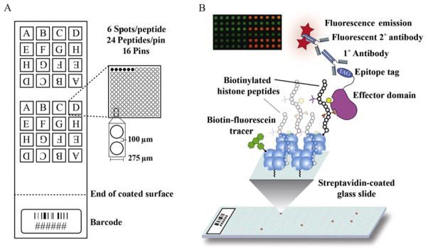
Slide design and workflow for peptide arraying. (A) A suggested layout of peptides for printing, as detailed in Chapter 3. (B) Depiction of the stepwise procedure for peptide arraying of an effector protein from peptide immobilization to antibody hybridization and visualization. Positive interactions are visualized as red fluorescence. All printed spots show green fluorescence from the biotinylated fluorescein printing control.
3.2. Biotinylated controls
In order to better control the quality of the data collected using peptide microarrays, a number of biotinylated control molecules are included. First, a fluorescent tracer (biotinylated fluorescein) is added to the microarray printing buffer (see Section 3.4), which can be used as a positive control for printing. This control allows for the distinction between an unprinted spot and a negative binding event. Similarly, we often recombinantly express proteins as fusions to glutathione-S-transferase (GST). Therefore, we include both biotinylated GST and a biotinylated IgG as positive controls for antibody binding in our hybridization assay (see Section 4). Biotinylation of protein controls is carried out using EZ-Link® Sulfo-NHS-Biotin (Thermo/Pierce Prod. No. 20217), according to the manufacturer’s instructions. Briefly, protein in phosphate-buffered saline (PBS), pH 7.6, was incubated with a 20-fold molar excess of EZ-Link® Sulfo-NHS-Biotin at room temperature for 1 h. Unreacted EZ-Link® Sulfo-NHS-Biotin was removed by extensive dialysis against PBS, pH 7.6.
3.3. Reducing sample carryover
One of the most difficult obstacles when printing peptide microarrays is cross-contamination of samples during printing. This is particularly an issue when arraying histone peptides that, in many cases, vary by only a single PTM. Furthermore, cationic peptides, such as histone peptides, have been reported to nonspecifically adsorb onto surfaces such as printing pins (Chico, Given, & Miller, 2003; Fuchs & Raines, 2005). Therefore, we employed several strategies to be able to both identify and reduce sample carryover. First, because our histone peptide library is made up of peptides from all four core histones, we arrange our sample printing plate such that two peptides derived from the same tail are never printed sequentially by one pin (Fig. 6.3A). This enables us to identify potential sample carryover, which would manifest as a large number of unexpected positive interactions on the microarray. Second, we observed that histone peptides become strongly adsorbed onto the surface of stainless steel pins. Note: we use a channeled Stealth 3 pin from Arrayit for printing. Carryover can also be decreased using a solid pin; however, channeled pins are able to print more spots per sample dipping and, thus, greatly decrease printing time. We find that adding an excess of bovine serum albumin (BSA) (1% w/v final concentration) effectively reduces nonspecific binding of histone peptides. Perhaps the most successful way to minimize sample carryover is to develop an effective washing protocol. Depending on the arrayer, you may have access to a flowing water bath and a sonicating bath. We found multiple rounds of alternating sonication and washing was most effective. Last, the addition of a single porous nylon slide (such as SuperNylon from Arrayit) as the last slide printed promotes absorption of any peptide remaining on the pin tip prior to washing.
3.4. Preparing the sample plate
Reagents
384 v-bottomed microplate
Powdered BSA
Fluorescein-labeled biotin
2× protein printing buffer (Arrayit)
Filtered distilled water (ddH2O)
Procedure
Prepare 100 μM stock solutions of each biotinylated histone peptide in 0.2 μm filtered ddH2O.
Add 3 μL of peptide stock to an appropriate well in a 384-well plate.
Assemble the microarray printing buffer (1× protein printing buffer, 1% BSA w/v, and 5 μg/mL fluorescein-labeled biotin), and add 7 μL to each well containing peptide.
Cover the plate with a plate seal to prevent evaporation and store refrigerated, if necessary, for no more than a few hours.
Immediately prior to printing, spin the plate in a centrifuge equipped with a microplate adaptor at 500×g for 2 min to collect samples and remove air bubbles.
3.5. Printing protocol
Equipment and reagents
Arrayer (such as Omnigrid 100 from Genomic Solutions/Digilab) equipped with HEPA air filtration
Vacuum source
Peristaltic pump with two 10 L wash reservoirs
Sonicating bath
Printing pin(s) (we used SMP6 Stealth pins from Arrayit)
Glass blotting pad (such as JMGR000U04)
Streptavidin-coated slides (such as SuperStreptavidin slides from Arrayit)
Nylon-coated slide (such as SuperNylon slide from Arrayit)
Humidifier
Filter paper
PBS, pH 7.6
Prior to printing
Prepare the arrayer by turning on the HEPA filtration unit and adjusting humidity, if necessary, to between 50% and 60%. Note: The proper level of humidity is crucial to a number of microarray printing aspects including spot morphology and pin drying.
Clean pins and printhead according to the manufacturer’s instructions. Regular cleaning of the printhead is essential to remove oxidation and prevent pin sticking. Likewise, pins should be cleaned between every printing.
Insert a test pin(s) and adjust the pin depth in the sonicating, washing, and drying stations according to the arrayer manufacturer’s instructions. Similarly, adjust the pin depth on the microscope slide microarray, the glass blot pad (if used), and the sample plate.
Setting printing parameters
Set printing parameters in the Z-direction. We used a velocity of 13.75 cm/s and acceleration and deceleration of 256 and 128 cm/s2, respectively, for both sample dipping and printing.
Set the wash program to direct pin washing between samples as follows: sonication 5 s/water wash 5 s (repeated 7×) followed by water wash 2 s/vacuum dry 2 s (repeated 5×) followed by vacuum dry for 5 s. Careful and complete washing is necessary to minimize carryover. Complete pin drying between samples is also critical to assure sample can be loaded onto pins.
Set sample loading parameters with pins dipping into sample 2×1 s and then being blotted 5× for 200 ms onto a glass blot pad.
Set pins to redip (2×1 s) into sample (without washing) once every 10–15 slides.
Printing
Carefully remove test pins from printhead.
Wipe the collars of the printing pins with a lint-free cloth and load into the printhead. Be cautious not to touch the pin tips and minimize inadvertent contact of the pin tip with the printhead.
Align blank streptavidin-coated microarray slides onto slide holders. We typically print a series (10–15 slides—see Step 7 above) of blank, uncoated microscope slides before the coated slides to remove any residual peptide that might have carried over from the previous sample. The last slide printed should be a SuperNylon slide (Arrayit), which aids in removal of excess sample prior to washing (see above).
Load the sample microplate and remove the plate cover.
Set program to start printing. Note: Exercise extreme care when the arrayer is in use as it is a large piece of equipment with moving parts. Observe the printing of at least one sample to ensure there are no errors or obstructions and make sure your equipment is accompanied with an emergency shut-off switch.
Postprinting processing
Typically, the printed spots will dry during the printing run. The relative success of the printing can be assessed by breathing on the underside of one of the blank slides, allowing the spots to appear. It is not uncommon to have occasional pin sticks throughout the run leading to blank areas. However, these are usually minimized by adhering to the instructions above (Steps 2, 3, and 9).
Place the printed slides, spots up, on a wet piece of filter paper in a humidified environment and place at 4 °C overnight. We do this by placing wet filter paper on large glass plates set at the bottom of a shallow cardboard box. We place a beaker of water in the box and cover the box with plastic wrap. This serves to rehydrate the spots, allowing greater interaction between the biotinylated peptides and the streptavidin-coated surface.
Place 200 μL of a biotin-containing blocking buffer, such as Super-Streptavidin blocking buffer (Arrayit), on each printed slide and carefully cover with a 25×60 mm coverslip. Incubate for 1 h at 4 °C to block the remaining microarray surface.
Wash the slides with PBS, pH 7.6, two times for 10 min each.
Dry slides quickly either by placing the slide in a 50-mL conical tube and centrifuging for 2 min at 800×g or by blowing dry with a stream of filtered air (laboratory forced air may contain oils and autofluorescent particulate matter).
Printed slides can be stored at 4 °C in the dark for at least 60 days. While longer-term storage, or storage at −20 °C or −80 °F, is theoretically possible, we have not yet performed studies to evaluate the length of time (and subsequent quality) of these arrays over time and after freezing.
4. ANALYSIS OF ANTIBODIES, EFFECTOR PROTEINS, AND ENZYMES
4.1. General hybridization protocol
Biotinylated histone peptide microarrays are a well-suited platform for semi-quantitative high-throughput interrogation of the binding specificity of antibodies and effector proteins. They have also proven useful for examining the influence that combinatorial PTMs have on the recognition of an effector protein. Additionally, the hybridization procedure outlined below can be modified to determine the substrate specificity of a histone-modifying enzyme (see Section 4.5). A typical workflow for effector protein analysis is depicted in Fig. 6.3B and detailed in the following section. All steps are performed at 4 °C with gentle rotation unless otherwise noted. Modifications to this protocol and general considerations are discussed in subsequent sections. Note: If necessary, the use of nitrile gloves is preferred, as the powder from some latex gloves emits fluorescence and should therefore be avoided when handling slide-based microarrays.
Equipment and reagents
Cold PBS, pH 7.6
Powdered BSA
Tween-20
Nontreated four-well dish (such Thermo #267061)
25×60 mm coverslips
Plastic container with lid
Whatman filter paper
Fluorescent-labeled secondary antibody (such as Invitrogen Alexafluor647-conjugated antirabbit (#A21244) or mouse (#A21235))
Microarray scanner capable of scanning at <25 μm resolution, equipped with analysis software (such as Typhoon Trio+ equipped with ImageQuant TL—GE Healthcare)
Procedure
Prepare the hybridization buffer (PBS, pH 7.6, 5% BSA w/v, 0.1% Tween-20).
Incubate the microarray slide with hybridization buffer in a nontreated four-well dish for 1 h to block nonspecific binding.
Prepare 200 μL of a 1 μM solution of your protein of interest in hybridization buffer.
Following the blocking step, place the microarray slide in a humidified chamber to prevent the slide from drying. Several options that work well in our hands are sealable Tupperware with a strip of damp Whatman paper or an elevated microscope slide incubation chamber with a well that can be filled with water.
Pipet drop-wise 200 μL of the protein solution directly over the region of the slide spotted with peptides. Carefully lay a coverslip over the slide, trying to minimize the presence of air bubbles.
Incubate at 4 °C overnight in the dark without rotation.
Remove the coverslip (should easily slide off as long as the microarray has not dried out) and wash the slide 3× for 5 min with PBS, pH 7.6.
Bound protein is detected by a series of antibody incubation steps. Prepare primary antibody dilution (specific to protein affinity tag) in hybridization buffer and incubate on the microarray for several hours with gentle rotation. The incubation time will vary depending on the antibody chosen, and this step may need optimization. Generally, 2–3 h is used as a starting point. It is helpful to print (along with the peptide library) a biotinylated primary antibody epitope or protein (in the case of GST) on the microarray as a positive control for this step.
Wash the slide 3× for 5 min with PBS, pH 7.6.
Prepare a fluorescent secondary antibody dilution (1:5000–1:10,000 for Alexafluor-647) in hybridization buffer and incubate slide for 30 min in the dark with gentle rotation. To optimize and control for secondary antibody binding, spot a biotinylated host-specific IgG on the microarray.
Wash the slide 3× for 5 min with PBS, pH 7.6, in the dark.
Dip the microarray several times in 0.1× PBS, pH 7.6, to remove excess salt.
Dry the slide by either filtered air or centrifugation in a 50-mL conical tube at 800×g for 2 min.
Proceed to the detection step. Fluorescent antibody signals may remain for 24 h or longer. However, for best results, it is recommended to scan the microarray slide within a few hours of incubation.
4.2. Hybridization considerations
4.2.1 Antibodies
Probing a microarray with a histone antibody is straightforward and can typically be completed within several hours. Blocking the microarray prior to antibody incubation is generally not necessary. The concentration of antibody hybridized to the microarray may need optimization. A recommended starting dilution should be within the range of detection by western blot that is empirically determined for the antibody (e.g., between 1:1000 and 1:50,000). The procedure described in Section 4.1 should be followed beginning at Step 8. The use of a coverslip for incubation is optional if reagent is limiting.
4.2.2 Effector proteins
The concentration of protein hybridized to the microarray is an important variable in the procedure detailed in Section 4.1. In our hands, a final concentration of 1–2 μM in hybridization buffer is sufficient for detection of binding interactions with low μM affinity. Incubation with higher concentrations of protein typically increases background, making detection and reproducibility more challenging. While most storage buffers are compatible with this microarray platform, it is best to dilute the protein as much as possible into hybridization buffer prior to arraying. Barring stability issues, we prefer to dialyze and store our proteins for arraying in PBS, pH 7.6, with up to 20% glycerol.
The labeling approach described in Section 4.1 relies on the recognition of an effector protein by an antibody specific to an epitope tag. We typically use either 6×-HIS or GST for both purification and detection. These tagging methods are our preferred choice due to the broad commercial availability of purification reagents and antibodies to recognize these epitopes, but other tagging methods should also work as long as an antibody is designed to recognize the native epitope. (Note: Others and we have observed that recombinantly expressed effector domains exhibit relatively low stability (data not shown). Therefore, we recommend arraying purified protein as soon as possible as storage at 4 °C or even at −80 °C leads to inconsistent results).
4.3. Alternative visualization techniques
The labeling approach described in Section 4.1 is advantageous due to the amplification of signal by layering 1° and 2° antibodies. However, alternative labeling approaches that minimize washing steps may be desired when working with low-affinity interactions or to minimize processing time. The microarray detection limit of the procedure described in Section 4.1 is roughly 20–30 μM. For antibodies, this is typically not an issue. However, many effector proteins bind weakly to histone tails, and more direct labeling methods such as the use of Alexafluor-conjugated primary antibodies or direct protein conjugation to a fluorescent probe or quantum dot may be desirable.
4.4. Microarray detection
Detection of microarray signals is performed using a flatbed fluorescent scanner. For simplicity, use of the Typhoon TRIO+ imager (GE Healthcare) is discussed in this section. However, this general procedure can be adapted for any scanner with similar capabilities.
Procedure
Place the microarray slide face down in a microarray slide holder. We use the GE #00-3759-30 AA. The slide holder allows for scanning of up to two microarrays and places the microarray at a uniform height (+3 mm) above the glass for accurate data collection. Position the slide holder in the lower left corner of the scanner. It is not advisable to place the slide directly on the scanner glass.
Set the scanner acquisition mode to fluorescence and select the 526 nm and 670 nm emission filter sets for the biotinylated fluorescein and secondary antibody, respectively.
Set the focal plane to +3 mm, check the Press Sample box, and set the orientation.
The scanning resolution should be set at 10 μm. It takes roughly 15 min/microarray to scan at this resolution.
4.5. Enzyme assays
In addition to scrutinizing the binding of antibodies and effector proteins, microarrays can also be used to probe the substrate specificity of histone-modifying enzymes. Unlike the binding of effector proteins and antibodies, which is primarily measured through indirect fluorescence hybridization, the activity of histone-modifying enzymes such as kinases and methyltransferases can be measured directly using radioisotopes. Kinases can be readily assayed on the microarrays we have described here using [γ-33P] ATP by quantifying transfer of the gamma phosphate group. The lower energy beta emissions of [γ-33P] ATP give better resolution of the spots; thus it is preferred over [γ-32P] ATP (Ptacek et al., 2005). After performing a kinase assay on the slide (similar to the hybridization protocol outlined in Section 4.1, but with the addition of a radiolabeled cofactor), phosphotransfer is most easily detected by exposing to film. The film can then be scanned and quantified. Detection of other enzymatic activities (such as methylation and acetylation) using these microarrays is possible but difficult because of the combination of the relatively low concentrations of peptide contained within each spot and the low emission energies of 3H or 14C. However, adjusting the size of the printed spot or printing onto different microarray surfaces (such as PVDF or nitrocellulose) can greatly increase the concentration of printed material.
5. DATA ANALYSIS
5.1. Statistical analysis and normalization
Signal intensities for each spot on a scanned microarray are determined by densitometry using a microarray analysis program such as ImageQuant TL (GE Healthcare) and autocorrecting for background by subtracting the local fluorescence spot edge average. We subsequently apply several statistical measures to the raw microarray results using a spreadsheet application such as Microsoft Excel. An initial filter is applied to remove individual spots whose biotinylated fluorescein intensity is less than 5% of the average intensity for all spots on the microarray. This removes peptides that were not efficiently spotted from further analysis. Peptides are printed (and subsequently quantified) as four independent subarrays (labeled A–H in Fig. 6.3A), which accounts for subtle differences in intensity across the slide. If set up according to Fig. 6.3A, each subarray contains all peptides—spotted six times each. Red channel intensities (corresponding to positive interactions) are then normalized for all spots by dividing the intensity value by the sum of all intensities within a subarray. The six spots for each peptide are then averaged, outliers are removed using a Grubbs test, and this average is then treated as a single value for each subarray. The four normalized values for each subarray (totaled from the four subarrays on the slide) are then used to calculate a mean, standard deviation, and standard error of the mean.
5.2. Data presentation
Presentation of peptide microarray data can take several forms, as depicted in Fig. 6.4. Scatter plots are informative for determining reproducibility across microarrays and for estimating the level of background signal for a given microarray. Figure 6.4A shows an XY scatter of two independent microarray experiments with a polyclonal antibody raised to recognize trimethylation at lysine 4 of histone H3 (H3K4) (Fig. 6.4A). Typically, the R2 value for antibodies is ≥0.9 and ≥0.8 for effector proteins (Fuchs et al., 2011). Importantly, the large number of features spotted allows for the statistical analysis of microarray results. Figure 6.4B depicts statistically significant differences in binding between different H3K4 methyl-containing peptides and the PHD domain of a V(D)J recombination factor, Rag2. Likewise, data can be visualized as a heatmap to show relative differences in binding for a larger number of peptides (Fig. 6.4C). We commonly normalize the mean calculated values to either the most intense value across all peptides or the peptide for which a given antibody or effector protein is known to interact, and data are plotted on a relative scale from 0 to 1 or −1 to 1, respectively.
Figure 6.4.

Typical data presentation for peptide array results. (A) Scatter plot showing the reproducibility of two arrays probed with an H3K4me3 antibody (Millipore #07-473, Lot #DAM1623866). Analysis of H3K4 methylation states shows no binding to H3K4me1-containing peptides (green), weak affinity for most H3K4me2-containing peptides (blue), and strong affinity for most H3K4me3-containing peptides (red) with the exception of several combinatorial PTMs that perturb binding to H3K4me3. All other peptides, including H3 peptides with no H3K4 methylation, are shown in black. (B) Array analysis of the PHD finger of the Rag2 V(D)J recombination factor identifies specificity for H3K4me3 as previously described (Ramon-Maiques et al., 2007). Peptide interactions were normalized to the average intensity of H3K4me3. Intensities were compared by two-way analysis of variance with 99% confidence intervals (**). (C) Heatmap depicting the effects of combinatorial PTMs on the binding of the Rag2 PHD finger to H3K4me3-containing peptides. Binding intensities are represented relative to H3K4me3 (0, white). Enhanced (1, red) and occluded (−1, blue) interactions are depicted. The heatmap was generated using JavaTreeView (Saldanha, 2004).
6. SUMMARY AND PERSPECTIVES
Peptide microarray methodologies have proven valuable for advancing our understanding of how histone PTMs (1) coordinate the binding of effector proteins, (2) alter the substrate specificity of histone-modifying enzymes, and (3) alter the specificity of the modification-specific antibodies we rely so heavily on for various techniques in chromatin biology (Bock et al., 2011; Fuchs et al., 2011; Fuchs & Strahl, 2011). The methods detailed in this chapter should serve as comprehensive guidelines for the various aspects of histone peptide synthesis, microarray fabrication and hybridization, and data analysis such that these approaches are accessible to any laboratory. While various microarray approaches have previously been described to assess the binding interactions with histone PTMs (Bock et al., 2011; Bua et al., 2009; Fuchs et al., 2011; Garske et al., 2010; Nady et al., 2008), we feel our approach offers several distinct advantages. Specifically, by synthesizing peptides individually, we have the ability to evaluate the purity of all peptides prior to printing. The inclusion of a biotin tracer is an important control for monitoring printing efficiency, which allows the user to filter potential false negatives that result from printing errors. Also, the redundancy of printed peptides (four groups of six spots printed by two different pins) allows for robust statistical analysis of binding interactions.
The ability to rapidly scrutinize the binding of proteins to thousands of peptides in a single experiment has its clear advantages, but as with any high-throughput proteomics screening method, there are several limitations to this technology. The generation of a high-quality biotinylated peptide library is at the root of the success of this methodology. Histone peptide synthesis is not trivial, even for the most experienced of peptide chemists. While many of the potential pitfalls of peptide synthesis are described herein, the seemingly endless variability in peptide design will inevitably pose a challenge. Furthermore, the threshold of detection following protein hybridization is undoubtedly the limiting factor for peptide arraying. We have difficulty detecting binding interactions with affinities weaker than 20–30 μM. For antibodies, this is not an issue. However, the dynamic interaction of effector proteins with histone PTMs often translates to weak binding affinities. A classic example is the binding of bromodomains to single acetyllysine residues, which is often measured with affinities >100 μM, and has been difficult for us to characterize on the microarrays.
Currently our microarray approach can only semiquantitatively assess the binding of effector proteins. Therefore, we feel our microarrays are suitable for determining whether a binding interaction is strong, weak, or undetectable. Importantly, these trends are reproducible with more quantitative biophysical approaches like ITC, surface plasmon resonance, or fluorescence polarization.
A number of enzymes and effector proteins have been identified to prefer nucleosomal substrates to peptides, therefore limiting the utility of peptide microarrays for these circumstances. This is currently a limitation for all histone peptide-based approaches. Recombinant nucleosomes carrying specific PTMs can be reconstituted in vitro, but these processes are labor intensive and not high-throughput. However, it is conceivable that a future high-density nucleosome array approach will also be developed to study how proteins and protein complexes interact with these larger structures.
Similar principles of PTM recognition by effector proteins govern biology beyond the chromatin landscape. Combinatorial PTMs have been shown to dictate the interactions of many biologically important proteins including RNA polymerase II and p53 (Fuchs, Laribee, & Strahl, 2009; Phatnani & Greenleaf, 2006; Sims & Reinberg, 2008). The adaptability of this microarray methodology for the design of nonhistone posttranslationally modified peptides is straightforward and will inevitably advance the progress toward deciphering both histone and more general protein PTM codes.
Acknowledgments
This work was supported by grants from the NIH (GM085394) and the North Carolina Biotechnology Center (NCBC) Institutional Development Grant (2010-IDG-I003) to BDS. SBR and SMF were supported by NIH postdoctoral grants T32CA09156 and F32GM80896, respectively. We thank the NCBC and the UNC School of Medicine for support in the establishment of the High Throughput Peptide Synthesis and Array Core Facility at UNC Chapel Hill.
Footnotes
Currently, commercially available only as a sodium salt: Fmoc-SDMA(Boc)2-ONa.
Note: Long air exposure may result in biotin tag and Met residue oxidation.
We replaced EDT with the almost odorless 3,6-dioxa-1,8-octanedithiol (TCI America).
Long air exposure of resin or crude peptide may result in oxidation of Cys and Met residues and biotin.
References
- Abelson JN, Simon MI, Fields GB. A practical guide. Oxford, UK: Elsevier; 1997. Solid phase peptide synthesis. [Google Scholar]
- Allis CD, Muir TW. Spreading chromatin into chemical biology. Chembiochem. 2011;12:264–279. doi: 10.1002/cbic.201000761. [DOI] [PubMed] [Google Scholar]
- Amblard M, Fehrentz JA, Martinez J, Subra G. Methods and protocols of modern solid phase Peptide synthesis. Molecular Biotechnology. 2006;33:239–254. doi: 10.1385/MB:33:3:239. [DOI] [PubMed] [Google Scholar]
- Bock I, Kudithipudi S, Tamas R, Kungulovski G, Dhayalan A, Jeltsch A. Application of Celluspots peptide arrays for the analysis of the binding specificity of epigenetic reading domains to modified histone tails. BMC Biochemistry. 2011;12:48. doi: 10.1186/1471-2091-12-48. [DOI] [PMC free article] [PubMed] [Google Scholar]
- Brownell JE, Zhou J, Ranalli T, Kobayashi R, Edmondson DG, Roth SY, et al. Tetrahymena histone acetyltransferase A: A homolog to yeast Gcn5p linking histone acetylation to gene activation. Cell. 1996;84:843–851. doi: 10.1016/s0092-8674(00)81063-6. [DOI] [PubMed] [Google Scholar]
- Bua DJ, Kuo AJ, Cheung P, Liu CL, Migliori V, Espejo A, et al. Epigenome microarray platform for proteome-wide dissection of chromatin-signaling networks. PloS One. 2009;4:e6789. doi: 10.1371/journal.pone.0006789. [DOI] [PMC free article] [PubMed] [Google Scholar]
- Chan WC, White PD. A practical approach. Oxford University Press; Oxford: 2000. Fmoc solid phase peptide synthesis. [Google Scholar]
- Chico DE, Given RL, Miller BT. Binding of cationic cell-permeable peptides to plastic and glass. Peptides. 2003;24:3–9. doi: 10.1016/s0196-9781(02)00270-x. [DOI] [PubMed] [Google Scholar]
- Coin I, Beyermann M, Bienert M. Solid-phase peptide synthesis: From standard procedures to the synthesis of difficult sequences. Nature Protocols. 2007;2:3247–3256. doi: 10.1038/nprot.2007.454. [DOI] [PubMed] [Google Scholar]
- Fuchs SM, Krajewski K, Baker RW, Miller VL, Strahl BD. Influence of combinatorial histone modifications on antibody and effector protein recognition. Current Biology. 2011;21:53–58. doi: 10.1016/j.cub.2010.11.058. [DOI] [PMC free article] [PubMed] [Google Scholar]
- Fuchs SM, Laribee RN, Strahl BD. Protein modifications in transcription elongation. Biochimica et Biophysica Acta. 2009;1789:26–36. doi: 10.1016/j.bbagrm.2008.07.008. [DOI] [PMC free article] [PubMed] [Google Scholar]
- Fuchs SM, Raines RT. Polyarginine as a multifunctional fusion tag. Protein Science: A publication of the Protein Society. 2005;14:1538–1544. doi: 10.1110/ps.051393805. [DOI] [PMC free article] [PubMed] [Google Scholar]
- Fuchs SM, Strahl BD. Antibody recognition of histone post-translational modifications: Emerging issues and future prospects. Epigenomics. 2011;3:247–249. doi: 10.2217/epi.11.23. [DOI] [PubMed] [Google Scholar]
- Gardner KE, Allis CD, Strahl BD. Operating on chromatin, a colorful language where context matters. Journal of Molecular Biology. 2011;409:36–46. doi: 10.1016/j.jmb.2011.01.040. [DOI] [PMC free article] [PubMed] [Google Scholar]
- Garske AL, Oliver SS, Wagner EK, Musselman CA, LeRoy G, Garcia BA, et al. Combinatorial profiling of chromatin binding modules reveals multisite discrimination. Nature Chemical Biology. 2010;6:283–290. doi: 10.1038/nchembio.319. [DOI] [PMC free article] [PubMed] [Google Scholar]
- Hilpert K, Winkler DF, Hancock RE. Peptide arrays on cellulose support: SPOT synthesis, a time and cost efficient method for synthesis of large numbers of peptides in a parallel and addressable fashion. Nature Protocols. 2007;2:1333–1349. doi: 10.1038/nprot.2007.160. [DOI] [PubMed] [Google Scholar]
- Howl J. Peptide synthesis and applications. Humana Press; Totowa, NJ: 2005. [Google Scholar]
- Huang Y, Fang J, Bedford MT, Zhang Y, Xu RM. Recognition of histone H3 lysine-4 methylation by the double tudor domain of JMJD2A. Science. 2006;312:748–751. doi: 10.1126/science.1125162. [DOI] [PubMed] [Google Scholar]
- Jenuwein T, Allis CD. Translating the histone code. Science. 2001;293:1074–1080. doi: 10.1126/science.1063127. [DOI] [PubMed] [Google Scholar]
- Klose RJ, Yamane K, Bae Y, Zhang D, Erdjument-Bromage H, Tempst P, et al. The transcriptional repressor JHDM3A demethylates trimethyl histone H3 lysine 9 and lysine 36. Nature. 2006;442:312–316. doi: 10.1038/nature04853. [DOI] [PubMed] [Google Scholar]
- Kornberg RD, Lorch Y. Twenty-five years of the nucleosome, fundamental particle of the eukaryote chromosome. Cell. 1999;98:285–294. doi: 10.1016/s0092-8674(00)81958-3. [DOI] [PubMed] [Google Scholar]
- Kouzarides T. Chromatin modifications and their function. Cell. 2007;128:693–705. doi: 10.1016/j.cell.2007.02.005. [DOI] [PubMed] [Google Scholar]
- Nady N, Min J, Kareta MS, Chedin F, Arrowsmith CH. A SPOT on the chromatin landscape? Histone peptide arrays as a tool for epigenetic research. Trends in Biochemical Sciences. 2008;33:305–313. doi: 10.1016/j.tibs.2008.04.014. [DOI] [PubMed] [Google Scholar]
- Nahtman T, Jernberg A, Mahdavifar S, Zerweck J, Schutkowski M, Maeurer M, et al. Validation of peptide epitope microarray experiments and extraction of quality data. Journal of Immunological Methods. 2007;328:1–13. doi: 10.1016/j.jim.2007.07.015. [DOI] [PubMed] [Google Scholar]
- Phatnani HP, Greenleaf AL. Phosphorylation and functions of the RNA polymerase II CTD. Genes & Development. 2006;20:2922–2936. doi: 10.1101/gad.1477006. [DOI] [PubMed] [Google Scholar]
- Ptacek J, Devgan G, Michaud G, Zhu H, Zhu X, Fasolo J, et al. Global analysis of protein phosphorylation in yeast. Nature. 2005;438:679–684. doi: 10.1038/nature04187. [DOI] [PubMed] [Google Scholar]
- Ramon-Maiques S, Kuo AJ, Carney D, Matthews AG, Oettinger MA, Gozani O, et al. The plant homeodomain finger of RAG2 recognizes histone H3 methylated at both lysine-4 and arginine-2. Proceedings of the National Academy of Sciences of the United States of America. 2007;104:18993–18998. doi: 10.1073/pnas.0709170104. [DOI] [PMC free article] [PubMed] [Google Scholar]
- Rothbart SM, Krajewski K, Nady N, Tempel W, Xue S, Badeaux AI, et al. Association of UHRF1 with H3K9 methylation directs the maintenance of DNA methylation. (Submitted) (Submitted to Nature 6/20/12) [Google Scholar]
- Ruthenburg AJ, Li H, Milne TA, Dewell S, McGinty RK, Yuen M, et al. Recognition of a mononucleosomal histone modification pattern by BPTF via multivalent interactions. Cell. 2011;145:692–706. doi: 10.1016/j.cell.2011.03.053. [DOI] [PMC free article] [PubMed] [Google Scholar]
- Ruthenburg AJ, Li H, Patel DJ, Allis CD. Multivalent engagement of chromatin modifications by linked binding modules. Nature Reviews. Molecular Cell Biology. 2007;8:983–994. doi: 10.1038/nrm2298. [DOI] [PMC free article] [PubMed] [Google Scholar]
- Saldanha AJ. Java Treeview—Extensible visualization of microarray data. Bioinformatics. 2004;20:3246–3248. doi: 10.1093/bioinformatics/bth349. [DOI] [PubMed] [Google Scholar]
- Shogren-Knaak M, Ishii H, Sun JM, Pazin MJ, Davie JR, Peterson CL. Histone H4-K16 acetylation controls chromatin structure and protein interactions. Science. 2006;311:844–847. doi: 10.1126/science.1124000. [DOI] [PubMed] [Google Scholar]
- Sims RJ, 3rd, Reinberg D. Is there a code embedded in proteins that is based on post-translational modifications? Nature Reviews. Molecular Cell Biology. 2008;9:815–820. doi: 10.1038/nrm2502. [DOI] [PubMed] [Google Scholar]
- Stathopoulos P, Papas S, Tsikaris V. C-terminal N-alkylated peptide amides resulting from the linker decomposition of the Rink amide resin: A new cleavage mixture prevents their formation. Journal of Peptide Science. 2006;12:227–232. doi: 10.1002/psc.706. [DOI] [PubMed] [Google Scholar]
- Strahl BD, Allis CD. The language of covalent histone modifications. Nature. 2000;403:41–45. doi: 10.1038/47412. [DOI] [PubMed] [Google Scholar]
- Subirós-Funosas R, El-Faham A, Albericio F. Aspartimide formation in peptide chemistry: Occurrence, prevention strategies and the role of N-hydroxylamines. Tetrahedron. 2011;67:8595–8606. [Google Scholar]
- Taunton J, Hassig CA, Schreiber SL. A mammalian histone deacetylase related to the yeast transcriptional regulator Rpd3p. Science. 1996;272:408–411. doi: 10.1126/science.272.5260.408. [DOI] [PubMed] [Google Scholar]
- Taverna SD, Li H, Ruthenburg AJ, Allis CD, Patel DJ. How chromatin-binding modules interpret histone modifications: Lessons from professional pocket pickers. Nature Structural & Molecular Biology. 2007;14:1025–1040. doi: 10.1038/nsmb1338. [DOI] [PMC free article] [PubMed] [Google Scholar]
- Vermeulen M, Eberl HC, Matarese F, Marks H, Denissov S, Butter F, et al. Quantitative interaction proteomics and genome-wide profiling of epigenetic histone marks and their readers. Cell. 2011;142:967–980. doi: 10.1016/j.cell.2010.08.020. [DOI] [PubMed] [Google Scholar]
- Whetstine JR, Nottke A, Lan F, Huarte M, Smolikov S, Chen Z, et al. Reversal of histone lysine trimethylation by the JMJD2 family of histone demethylases. Cell. 2006;125:467–481. doi: 10.1016/j.cell.2006.03.028. [DOI] [PubMed] [Google Scholar]