

Abstract
A hybrid neuroprosthesis (HNP) combines lower extremity bracing with functional neuromuscular stimulation (FNS) to restore walking function and enhance the efficiency of ambulation. This report details the development of a novel HNP containing a variable impedance knee mechanism (VIKM) capable of supporting the knee against collapse while allowing controlled stance phase knee flexion. The design of a closed loop, finite state controller for coordination of VIKM activity with FNS-driven gait is presented. The controller is verified in testing during able bodied gait. The improved functionality provided by this system has the potential to delay the onset of fatigue and to expand FNS driven gait to allow walking over uneven terrains and down stairs.
I. Introduction
FUNCTIONAL neuromuscular stimulation (FNS) is a technique used to restore function to muscles paralyzed after a spinal cord injury (SCI). Significant research has been conducted on the use of FNS to restore functional walking to individuals with paraplegia from SCI [1], [2]. Such systems stimulate the paralyzed muscles to restore forward propulsion during swing and to support body weight during stance. Most of these systems utilize an open-loop control system with a reduced number of stimulation channels compared to lower extremity degrees of freedom. This often results in gait composed of unnatural trajectories during swing and a stiff leg during stance. The lack of a closed loop feedback system requires higher levels of stimulation than are necessary resulting in rapid fatigue of lower extremity muscles due to high stimulation duty cycle.
The field of hybrid neuroprostheses (HNP) was developed to address these problems [1]. HNPs combine FNS and controllable lower extremity bracing to create a system which combines the advantages and minimizes the shortcomings of each independent approach. In the past, the HNP strategy has split walking into two main functional stages: limb propulsion (accomplished by FNS) and body weight support (accomplished by bracing). The first HNP systems combined FNS with conventional trunk-hip-knee-ankle-foot orthoses to provide reciprocal gait to individuals with paraplegia. The resulting systems allowed users to walk further than with either FNS-only or brace-only systems [3]. Integrating controllable mechanisms to lock lower extremity joints provides the opportunity to support body weight while reducing stimulation duty cycle. Significant effort has been dedicated toward the development of a controllable knee mechanism which can support the knee during stance and allow unencumbered movement during swing [4]. Other devices have focused on improving the coordination of leg function during gait [5]-[7].
Much of the effort to date has been on locking the knee joint during stance phase to support body weight, yet considerable evidence suggests that it may be advantageous to allow some degree of knee motion during stance. Intelligent prosthetics which incorporate this capability are shown to offer some benefit over prosthetic knees which simply lock the knee during stance [8], [9].
We hypothesize that integration of a mechanism capable of regulating stance phase knee flexion in a HNP can significantly expand the functionality of gait in individuals with SCI. Potential benefits of stance knee flexion include reduced force and prevention of knee hyperextension at impact, maintenance of forward progression throughout stance, and reduction of hip power required during pre-swing for toe clearance. During normal walking, stance knee flexion is produced by eccentric actions of knee extensor muscles. Stance knee flexion is difficult or impossible to attain with current FNS systems because the eccentric contractions required can not be adequately controlled with conventional electrical stimulation. Incorporation of a mechanism which can permit and regulate knee flexion during stance phase will enable more natural and efficient gait while reducing stimulation duty cycle and delaying muscle fatigue. Unlike FNS-only or knee locking HNP systems, an HNP which provides this function can expand the ability of the user to walk over varied terrains and descend stairs in a forward manner.
We have previously reported the design and testing of a variable impedance knee mechanism (VIKM) capable of regulating knee flexion through the use of a magnetorheological damper [10]. In this report, we detail the design and testing of a closed loop controller which can regulate knee flexion during walking. The ability of the controller to accurately synchronize behavior of the VIKM with the gait cycle is examined during able bodied walking.
II. Methods
A. Controller Development
The objective of this research is to combine an implanted FNS system with a controllable orthosis containing a trunk corset, leg uprights, and a variable impedance knee mechanism (VIKM) to create a hybrid neuroprosthesis (HNP) (Fig. 1). The objective of this hybridization is to utilize the VIKM to support the knee during stance phase to (1) reduce the stimulation duty cycle of knee extensors by eliminating the need for muscles to support body weight and (2) restore stance phase knee flexion during loading response and pre-swing. The reduced duty cycle has the potential to delay the onset of fatigue of the stimulated muscles; the restored stance phase knee flexion has the potential to enhance gait efficiency by reducing hyperextension and force on the leg at impact as well as reducing the hip flexion power required at toe-off.
Fig. 1.
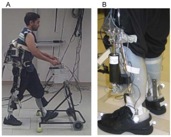
(a) Able bodied subject walking with a trunk-hip-knee-ankle-foot orthosis containing the VIKM. (b) The prototype VIKM.
Traditionally, FNS systems restore walking function using an open-loop control system that appropriately coordinates muscle actions via a preprogrammed stimulation pattern (the baseline pattern). A closed-loop feedback controller was developed to modulate stimulation and activity of the VIKM during gait. There are two objectives of the controller. The first is to synchronize the VIKM operation with the FNS activity dictated by the baseline pattern. The second is to modulate the baseline FNS pattern in real-time such that stimulation of target muscles is turned off when the VIKM is active. Specifically, the goal is to activate the VIKM during loading response, terminal stance, and pre-swing phases. The active VIKM will support body weight and regulate stance knee flexion thereby allowing the stimulation of knee extensor muscles to be turned off at these times. The mechanical advantage of a flexed knee during pre-swing may also enable a reduction in hip flexor stimulus intensity during that phase. The VIKM is inactive during mid-stance and swing, allowing FNS to produce the joint dynamics necessary for ambulation.
The distinct behavior of the knee during the six phases of gait suggests that a finite state machine can be implemented to control the VIKM during walking. Previous studies have indicated that a sensor set which monitors lower extremity joint angles and foot contact is capable of reliably identifying gait phase during FNS-driven gait [11]; finite state machines have also been employed to control lower extremity prosthetics [12].
For the purposes of this system, the gait cycle has been divided into 5 states which are identified by comparing six feedback signals to thresholds (Table 1). The thresholds for knee angle and angular velocity are shown in Table 2. The finite state machine also utilizes the baseline pattern to assist in classification of the gait phase. The FNS feedback control signal is derived from the activity of the knee flexors; the FNS pre-swing feedback signal is high (1) at a pre-defined time (approximately 10% of the gait cycle) before the onset of knee flexor stimulation and then is returned to low (0) at the onset of flexor stimulation. This feedback signal is possible because of the consistent coordination between muscle group activation during gait. The real time modulation of the FNS turns off stimulation to target muscle groups (knee extensors), but the relative timing of muscle activation in not altered from the baseline pattern.
TABLE I.
Finite State Controller for Variable Impedance Orthosis
| Condition → | Ipsilateral Heel Contact |
Contralateral Foot Contact |
Knee Angle > Threshold 1 |
Knee Angle < Threshold 2 |
Knee Angular Velocity < Threshold 3 |
FNS Pre-Swing Feedback |
|---|---|---|---|---|---|---|
| State ↓ | ||||||
| Loading Response | 1 | 1 | 0 | 0 | 0 | 0 |
| Mid-Stance | 1 | 0 | 0 | 0 | 1 | 0 |
| Terminal Stance | 1 | 0 | 0 | 1 | 0 | 0 |
| Pre-Swing | 0 | 1 | 0 | 1 | 0 | 1 |
| Swing | 0 | 1 | 1 | 0 | 0 | 0 |
The finite state machine classifies gait into five states based on evaluation of the conditions shown; a value of 1 indicates that the condition has been met, while a value of zero indicates it has not. Thresholds are given in Table 2 The term foot contact refers to either heel or forefoot contact.
TABLE II.
Finite State Controller Thresholds
| Threshold 1 | 15° |
| Threshold 2 | 3° |
| Threshold 3 | −6°/sec |
The knee angle and angular velocity thresholds used by the finite state controller. Positive angles indicate flexion, negative extension (0° is full extension).
Because the VIKM is only active during stance phase, swing was combined into a single gait phase. The controller breaks stance into four phases: loading response, mid-stance, terminal stance, and pre-swing. The VIKM is active and regulates knee flexion during loading response and pre-swing. The VIKM is inactive during mid-stance to allow FNS to extend the stance limb to assist in forward progression and ensure the contralateral leg is able to clear the floor during swing. The VIKM actively supports body weight during terminal stance without allowing knee flexion.
During states when the VIKM damper regulates knee flexion, a proportional controller is employed to adjust the VIKM resistance to knee motion based on angular velocity. The VIKM uses a magnetorheological fluid damper to provide variable resistance which is proportional to the supplied current. A pulse width modulation scheme is utilized to control the average current supplied to the damper. The dampers are connected to a boosted 12 V power supply through a MOSFET with its gate driven by an 800 Hz signal. An onboard microcontroller sets the duty cycle of the gate signal based on the output from the proportional controller through the use of digital signals - three for each damper – providing eight different levels of damping resistance. Details on the resistive torque provided by the VIKM can be found in [10]. When active, the VIKM is subjected to supervisory thresholds based on knee angle. If the knee flexes beyond a preset threshold the damper automatically increases to maximal resistance, providing up to 64.5 N-m of torque at the knee to prevent user collapse.
B. Sensors for Feedback Signals
The finite state controller uses signals collected from sensors mounted on the VIKM orthosis to determine gait phase. Because a linkage is employed at the knee joint, linear potentiometers (ALPS Electric, Campbell, California USA) measured the linear displacement of the damper within the VIKM which was then mapped to knee angle. Knee angle measurements were differentiated to determine angular velocity. Force sensitive resistors (FSRs) (B&L Engineering, Tustin, CA USA) were used to measure foot-ground contact by placing one at the first phalange, first and fifth metatarsals, and the heel. The signals from the three forefoot FSRs were summed to a single signal representing the forefoot. Because the finite state controller required only foot contact information the outputs of the forefoot and heel FSRs were normalized by their value during stance. Foot contact was then sensed when the output of either forefoot or heel was above 90% of this value.
All sensor signals were sampled at a frequency of 200 Hz. The signals were low-pass filtered using 5th-order Butterworth filters with cutoff frequencies of 10 Hz for the potentiometers and 20 Hz for the FSRs. The VIKM finite state controller and data acquisition software was developed and implemented in the Matlab Simulink® xPC Target real time environment (The Mathworks, Inc., Natick, MA USA). Isolated, multi-conductor cables are used to connect the orthosis to the control computers.
C. Testing in Able Body Walking
The finite state controller and VIKM activity were evaluated during level ground walking with one able bodied individual over two sessions. The purpose of the able bodied testing was to verify that the controller could accurately determine gait phase and synchronize VIKM behavior during normal walking. The individual recruited in this study signed a consent form approved by an institutional review board prior to participation.
No FNS system was utilized during the able bodied experiments, so the FNS pre-swing feedback control signal was not present. Two VIKM orthoses were installed on uprights connected to a trunk corset with hip joints that restricted motion of the user to the sagittal plane. The ankle joints of the orthosis remained locked in the sagittal plane to accurately recreate the walking constraints experienced by individuals with SCI. The subject utilized a standard walker for additional stability. The walker was fitted with two six axis load cells (AMTI, Watertown, MA USA) to monitor the upper extremity forces during gait. The subject was instructed to walk at a self-selected pace along a ten meter walkway while wearing the VIKM orthoses. Approximately 46 strides of data were collected and analyzed.
A Vicon® MX40 motion capture system (Vicon Motion Systems, Oxford, UK) tracked the kinematics during walking. These data were used to verify the joint angles and gait events observed and computed by the control system sensor set and controller.
III. Results
The finite state machine was able to accurately synchronize the behavior of the VIKM with able bodied gait (Fig. 2). The subject walked with an average cadence of 41.2 ± 3.1 steps/min, average step length of 0.55 ± 0.142 m, and average speed of 0.38 ± 0.02 m/sec.
Fig. 2.
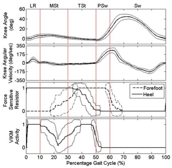
Knee behavior, foot contact, and VIKM damper activity during able bodied walking averaged over the gait cycle ± one std. dev. A value of 1 indicates the VIKM damper is active, while 0 indicates it is inactive. Gait events are indicated as defined in [13].
At the start of the gait cycle – immediately following heel contact – the damper is active (Fig. 2), allowing stance phase knee flexion to approximately 10°, which is less than threshold 1 (15°). As the cycle progresses, the knee extends and reaches an extension velocity greater than threshold 3 (−6°/sec), resulting in damper deactivation at the beginning of mid-stance. Knee extension continues until the knee reaches near full extension by passing threshold 2 (3°). At this point, the damper activates to support the knee during terminal stance. As the heel comes off the ground, the VIKM deactivates to allow knee flexion during pre-swing. The damper remains inactive for the duration of swing phase.
No significant changes in upper extremity force or spatiotemporal gait parameters (cadence, stride length, and gait speed) were seen between walking trials with the finite state controller activating the VIKM and walking trials during which the VIKM remained inactive through the entire gait cycle. These data reflect the controller’s capability to accurately synchronize VIKM activation with the user’s gait.
IV. Discussion
The finite state controller was designed to synchronize the behavior of the VIKM orthosis with FNS driven limb motion during walking. Able bodied gait therefore provides an accurate test bed to evaluate its performance. The activation pattern of the VIKM is similar to that of eccentric knee extensor muscle activity during the early parts of stance (Fig. 2); knee flexion is regulated by an active VIKM at impact and throughout loading response. The VIKM is inactivated during mid-stance phase to allow knee extension. The objective of the VIKM during late mid-stance and terminal stance phases is to support the limb to allow FNS of knee extensor muscles to be turned off. When the knee reaches full extension after loading response (20-30% of the gait cycle) the VIKM is activated. This support is unnecessary for able bodied gait, but is critical during FNS driven gait to allow stimulation to be turned off without knee collapse.
Unlike impact absorbance, flexion during pre-swing is not actively regulated by muscle excitation, but instead is primarily an indirect result of actions at the hip and ankle to drive the body forward. Activation of knee extensors only occurs during pre-swing if knee flexion becomes excessive [13]; likewise the VIKM is not activated during pre-swing unless knee flexion passes a physiologic threshold (20°) prior to toe-off; this was not observed in able bodied gait.
The data presented in Fig. 2 show VIKM activation as an on-off event (0 or 1). The damper within the VIKM is capable of eight different levels of resistance [10]. The resistance provided is proportional to knee angular velocity and is increased only when it exceeds a pre-set threshold (180°/sec). During the able body testing, the damper was never active above the minimum resistance because the stance phase flexion velocity never crossed this threshold.
The knee angle during walking with the VIKM orthosis is slightly diminished from that of normal gait. The reduced gait speed and constricted step length are likely due to the leg braces as well as the passive resistance of the VIKM mechanism, which is approximately 2 Nm [10]. However, this value is well below the FNS torque generation capability of the paralyzed knee flexors [2].
The data presented here indicate the controller is able to activate the VIKM appropriately during walking. When combined with an implanted FNS system, VIKM activation should allow stimulation of knee extensor muscles to be reduced during stance phase. In addition to reducing stimulation duty cycle, the VIKM could improve the functionality of FNS restored gait by regulating knee flexion during stance. Restoring this capability has potential to reduce loading on the limb during impact absorbance, decrease hip power required at toe-off, and allow FNS-restored walking over uneven terrains and down stairs.
Acknowledgments
This work was supported in part by the Department of Veterans Affairs under Grant A6404R and in part by the Department of Defense under Grant PR043074. T.C. Bulea was also supported in part by NIH/NIAMS under Grant T32 AR007505.
Contributor Information
Thomas C. Bulea, Department of Biomedical Engineering, Case Western Reserve University, Cleveland, OH 44106 USA (tcb9@case.edu)..
Rudi Kobetic, Motion Study Laboratory, Louis Stokes Cleveland Department of Veterans Affairs Medical Center, Cleveland, OH 44106 USA (rkobetic@fescenter.org)..
Ronald. J. Triolo, Department of Orthopaedics, Case Western Reserve University, Cleveland, OH 44106 USA, and also with the Louis Stokes Cleveland Department of Veterans Affairs Medical Center, Cleveland, OH 44106 USA (ronald.triolo@case.edu)..
References
- [1].Nene AV, Hermens HJ, Zilvold G. Paraplegic locomotion: A review. Spinal Cord. 1996;vol. 34(no. 9):507–524. doi: 10.1038/sc.1996.94. [DOI] [PubMed] [Google Scholar]
- [2].Kobetic R, Marsolais EB. Synthesis of paraplegic gait with multichannel functional neuromuscular stimulation. IEEE Trans. Rehab. Eng. 1994;vol. 2(no. 2):66–79. [Google Scholar]
- [3].Solomonow M, Aguilar E, Reisin E, Baratta RV, Best R, Coetzee T, D’Ambrosia R. Reciprocating gait orthosis powered with electrical stimulation (RGO II). Part I: Performance evaluation of 70 paraplegic patients. Orthopedics. 1997;vol. 20(no.4):315–324. doi: 10.3928/0147-7447-19970401-08. [DOI] [PubMed] [Google Scholar]
- [4].Yakimovich T, Lemaire ED, Kofman J. Engineering design review of stance-control knee-ankle-foot orthoses. J. Rehabil Res Dev. 2009;vol. 46(no. 2):257–267. [PubMed] [Google Scholar]
- [5].Gharooni S, Heller B, Tokhi MO. A new hybrid spring brake orthosis for controlling hip and knee flexion in the swing phase. IEEE Trans. Neur. Sys. Rehab. Eng. 2001;vol. 9(no.1):106–107. doi: 10.1109/7333.918283. [DOI] [PubMed] [Google Scholar]
- [6].Greene PJ, Granat MH. A knee and ankle flexing hybrid orthosis for paraplegic ambulation. Med. Eng. Phys. 2003;vol. 25:539–545. doi: 10.1016/s1350-4533(03)00072-9. [DOI] [PubMed] [Google Scholar]
- [7].Farris RJ, Quintero HA, Withrow TJ, Goldfarb M. Design of a joint-coupled orthosis for FES-aided gait. Proc. 11th IEEE Int. Conf. on Rehab. Robotics.2009. pp. 246–252. [Google Scholar]
- [8].Buckley JG, Spence WD, Solomonidis SE. Energy cost of walking: comparison of “intelligent prosthesis” with conventional mechanism. Arch. Phys. Med. Rehab. 1997;vol. 78:330–333. doi: 10.1016/s0003-9993(97)90044-7. [DOI] [PubMed] [Google Scholar]
- [9].Johansson JL, Sherrill DM, Riley PO, Bonato P, Herr H. A clinical comparison of variable-damping and mechanically passive prosthetic knee devices. Am. J. Phys. Med. Rehab. 2005;vol. 84:563–575. doi: 10.1097/01.phm.0000174665.74933.0b. [DOI] [PubMed] [Google Scholar]
- [10].Bulea TC, Kobetic R, To CS, Audu M, Schnellenberger J, Triolo RJ. A variable impedance knee mechanism for controlled stance flexion during pathological gait. IEEE/ASME Trans Mechatron. in press. [Google Scholar]
- [11].Skelly MM, Chizeck HJ. Real-time gait event detection for paraplegic FES walking. IEEE Trans. Neur Sys Rehab Eng. 2001;vol. 9(no. 1):59–68. doi: 10.1109/7333.918277. [DOI] [PubMed] [Google Scholar]
- [12].Sup F, Bohara A, Goldfarb M. Design and control of a powered transfemoral prosthesis. Int. J. Robot. Res. 2008;vol. 27(no. 2):263–273. doi: 10.1177/0278364907084588. [DOI] [PMC free article] [PubMed] [Google Scholar]
- [13].Perry J. Gait analysis: normal and pathological function. McGraw-Hill, Inc.; New York, NY: 1992. [Google Scholar]