

Abstract
Many biological processes rely on membrane fusion, therefore assays to study its mechanisms are necessary. Here we report an assay with sensitivity to single-vesicle, even to single-molecule events using fluorescently labeled vesicle-associated v-SNARE liposomes and target-membrane-associated t-SNARE-reconstituted planar, supported bilayers (SBLs). Docking and fusion events can be detected using conventional far-field epifluorescence or total internal reflection fluorsecence microscopy. Unlike most previous attempts, fusion here is dependent on SNAP25, one of the t-SNARE subunits that is required for fusion in vivo. The success of the assay is due to the use of (i) bilayers covered with a thin layer of poly(ethylene glycol) to control bilayer-bilayer and bilayer-substrate interactions, (ii) microfluidic flow channels which presents many advantages such as the removal of non-specifically bound liposomes by flow. The protocol takes 6–8 days to complete. Analysis can take up to two weeks.
Keywords: Cell biology, imaging, membrane dynamics, biophysics, microfluidics, membrane fusion, supported bilayer, SNARE proteins, total internal reflection fluorescence microscopy
INTRODUCTION
Membrane fusion is required for fundamental processes such as fertilization, infection by enveloped viruses, intracellular trafficking, and secretion of neurotransmitters and hormones. The first direct evidence that SNAREs (soluble N-ethylmaleimide-sensitive factor attachment protein receptors) mediate membrane fusion came from a bulk in vitro fluorescence dequenching assay used to monitor fusion between proteoliposomes reconstituted with cognate vesicular- (v) and target- (t) SNAREs 1. The bulk liposome fusion assay and its various derivatives have provided much of our mechanistic understanding of SNARE-mediated fusion and its regulation by lipids and auxiliary proteins 2. It is easy to implement and analysis is straightforward. However, the assay suffers from a number of limitations such as low sensitivity and time resolution, and that it detects the cumulative effects of vesicle docking and fusion. In addition, a key intermediate state named hemifusion (in which the proximal leaflets of two bilayers have fused but not the distal ones) cannot be readily detected. To overcome these limitations, intense efforts have focused on developing new assays that can detect single-vesicle docking and fusion events.
Two assays have emerged that have been shown to be capable of reproducing physiological observations and providing new mechanistic insights. The first assay was developed in the laboratory of T. Ha, and monitors fusion between surface-tethered v-SNARE reconstituted vesicles and t-SNARE reconstituted vesicles in the bulk in a flow cell (“tethered-vesicle fusion assay”) 3–6). Single-vesicle docking and fusion events are monitored using fluorescence resonant energy transfer (FRET) between acceptor and donor lipid labels in the tethered and bulk vesicles, respectively. The tethered-vesicle fusion assay is described in detail in a protocol by Diao et al. 7.
The second assay is the subject of this protocol. It was developed by our group, and is used to study mechanisms of fusion by the exocytic/neuronal v-SNARE VAMP-2/Synaptobrevin and t-SNAREs Syntaxin-1 and SNAP25 8,9. This assay monitors single-vesicle docking and fusion events between t-SNARE reconstituted planar, supported bilayers (t-SBLs) and v-SNARE reconstituted bulk small unilamellar vesicles (v-SUVs) in microfluidic flow channels (“SUV-SBL fusion assay”). Inclusion of a fluorescent lipid (lissamine-rhodamine derivatised phosphatidyl ethanolamine, LR-PE) enables the v-SUVs to be detected as they dock and fuse with the supported bilayer either using conventional far-field epifluorescence microscopy or total internal reflection fluorescence microscopy (TIRFM). Both detection approaches are sensitive to single docking and fusion events 8,9; however TIRFM provides enough sensitiviy that release of single lipid-linked fluorophores from the v-SUV into the t-SBL upon fusion can be monitored with ~15 ms time resolution 8,9.
Experimental design
The planar supported bilayer
Planar bilayers supported on a substrate was first pioneered by McConnell 10,11. Advantages of a fusion assay in which SUVs dock and fuse with planar, supported bilayers was recognized about a decade ago and was first applied to neuronal/exocytic SNARE mediated fusion by the Rothman laboratory who visualized docking and fusion of single v-SUVs with t-SBLs for the first time 12. That study was rapidly followed by similar approaches developed by the Chu and Brunger 13, and Weisshaar and Chapman 14 groups. However, the methods used in these studies have failed to faithfully reconstitute some crucial aspects of fusion as it occurs in vivo. Most notably, fusion was found to be independent of SNAP25, an absolutely required subunit of the t-SNARE in vivo. In addition, conflicting results regarding the efficiency, calcium-dependence, and rates of fusion were reported. It is very likely these difficulties arise from a lack of control of supported bilayer-substrate interactions, a problem that has traditionally been a limitation in supported bilayer research, especially when trans-membrane domain (TMD) proteins are included.
To remedy this problem, we have taken two approaches. First, by including a fraction of lipids that are covalently linked to a poly-(ethylene glycol) (PEG) chain, inter-bilayer and bilayer-substrate interactions can be controlled by varying the density and length of the PEG chains. The second approach is the use of microfluidic flow channels for controlled deposition of SBLs. Under these conditions, fusion of v-SUVs with t-SBLs containing both subunits of the t-SNARE (syntaxin-1 and SNAP25) is more than ten times faster than with SBLs containing only the syntaxin-1 subunit 8.
Polymer brushes to control bilayer-substrate and inter-bilayer interactions
PEG chains grafted onto a bilayer behave similarly to polymers present at interfaces 15–17. At low densities, the grafted PEG chains do not interact laterally on the surface, and form “mushrooms” whose configurations are only slightly different to those of free chains in solution 15–17. At densities above the overlap threshold (when the chains just touch laterally), polymer brushes are formed, wherein lateral interactions squeeze the chains in the plane of the grafted surface and force them to extend them in the direction normal to it 15–17. These considerations apply when – apart from the graft point– the chains interact with the bilayer in a repulsive manner. When two surfaces with grafted chains are brought into close proximity, a second critical density −0.25 times the overlap threshold– arises beyond which interpenetration of chains from the two surfaces is sterically hindered 16. PEG is a polymer with some peculiar properties which are at least partly due to solvent-mediated structuring 18–20. Consequently scaling 15 or mean-field 17 theories which ignore such detailed interactions can only be taken as a rough starting point. Nonetheless, x-ray 16 and neutron reflectometry 21 measurements of PEGyleated bilayers are at least qualitatively consistent with expectations from idealized polymer theories.
When polymers are grafted onto soft surfaces such as lipid bilayers, additional phenomena may arise. When grafting density is low, or when polymers cover only one of the two surfaces of a bilayer, the grafted chains will tend to bend the membrane to increase the configurations available to them 22. Bending effects are not important in our assay because brushes cover both sides of a bilayer at the same density and the bending forces balance. Finally, at very high PEG coverage (>15–20 mole % for PEG2K) segregation might occur into PEGylated-lipid-rich and - poor phases 23.
Properties of PEGylated liposome bilayers have been extensively studied due to their use for drug delivery applications 24. The biocompatible, well-hydrated PEG layer is very efficient in sterically inhibiting non-specific adhesion onto bilayer surfaces. Crucial to the success of the fusion assay, use of PEGylated lipids introduces a fully hydrated, soft cushion between the planar, supported bilayer and the glass coverslip substrate. The thickness and density of the cushion can be varied to tune its properties.
Inclusion of a soft cushion between the SBL and the substrate critically improves functional reconstitution of transmembrane proteins, therefore many strategies have been developed to achieve cushioned, or tethered SBLs 21,25–33, some of which have been commercialized (SDx Tethered Membranes Pty Ltd, Sydney). However, many strategies involve sophisticated surface chemistry, rapid exchange from oil to aqueous phase, or use of Langmuir-Blodgett deposition techniques which are complicated, may influence fusion properties, or are incompatible with microfluidics. In contrast, use of PEGylated liposomes for forming SBLs is simple, oil-free, and compatible with microfluidics. PEGylated liposomes adsorb onto very clean, hydrophilic glass (or quartz) surfaces, where the favorable PEG-substrate adsorption energy drives the spread of the bilayers to the point of rupture of the liposomes, followed by healing of the defects by fusion. The group of P. Cremer has pioneered use of PEGylated SBLs with the aim of developing biosensors 34. Such SBLs can withstand cycles of drying and rehydration without any apparent degradation, presumably because the PEG brush prevents complete dehydration of the bilayers 25. In addition, transmembrane proteins have high mobilities and activities in PEGylated SBLs35. Lin et al. measured the electrical resistance of PEGylated SBLs as a function of PEG-lipid tether density and found that the highest resistance (lowest defect density) occurs near the overlap threshold, at 5–6 mole % for PEG2000-PE28.
Use of PEGylated bilayers in membrane fusion requires a further consideration, namely that the brushes should not significantly hinder the proteins located in apposed membranes from interacting in trans. This is achieved by choosing the brush height to be smaller than the size of the proteins. The cytosolic domain of the v-SNARE Vamp-2/Synaptobrevin-2 is mostly unstructured when free36,37, thus to a first approximation it can be modeled as a random coil, with a persistence length lp ≈ 5 residues × 0.38 nm/residue ≈1.9 nm38. Using the wormlike chain model with a contour length L = 35.7 nm (94 residues), an unperturbed radius of gyration Rg ≈ 4.4 nm and a root mean squared end-to-end distance RN ≈ 11nm are predicted38. The t-SNARE acceptor complex composed of Syntaxin-1 and SNAP25 is structured, with the SNARE domain being roughly a cylinder of 12 nm length.
Given all the considerations and constraints above, we chose to have brushes that are ~4–5 nm thick and have PEGs that are at the vicinity of the overlap threshold, by using 5 mole % PEG2000-PE (PEG MW=2000, corresponding to ~45 monomer units). Small variations in PEG density around this value (~3–7 mole %) do not seem to affect SBL formation or fusion, but we have not undertaken a systematic study of the effects of PEG chain length and density on the experimental results. Because VAMP-2/Synaptobrevin-2 is surrounded by a PEG brush, it is likely to be extended slightly further than its unperturbed dimension estimated above and should be somewhat protruding from the PEG brush (Figure 1).
Figure 1.

The experimental setup. (A) Schematic of a v-SUV and a t-SBL. (B) Schematic drawing of the microfluidic flow system. (C) Photograph of the assembled microfluidic device on the microscope stage. Various components are labeled. (D) Close-up view of the assembly.
A very important aspect of the use of PEGylated bilayers is that it provides a realistic mimic of biological membranes in which every square micron is occupied by 30,000–40,000 integral membrane proteins39. This dense repulsive layer of protein must be cleared from the fusion site to allow interbilayer contact. The 5 mole % PEG2000-PE used here corresponds to ~70,000 PEGs/μm2, each chain filling a volume of ~60–70 nm3, corresponding to the soluble domain of a typical folded globular protein of 50–60 kDa.
Microfluidics
Use of microfluidic channels, each having a volume of less than1 μl, allows the use of very small amounts of sample and monitoring several conditions side-by-side on the same coverslip. The entire experiment is run under constant flow, for several reasons: (i) the flow carries away weakly, and presumably non-specifically bound v-SUVs13, (ii) bulk v-SUV concentration remains constant, simplifying analysis14, (iii) when far-field epifluorescence is used for detection (see below), vesicles in bulk appear as streaks due to the flow, making them easily distinguishable from docked vesicles. With typical flow rates of 1–3 μl/min, only 60–180 μl sample is consumed per channel per hour. Continuous flow would be impractical without the use of microfluidic channels, since much larger volumes of sample would be consumed.
We find SBLs that are formed in microfluidic cells with well-controlled flow rates are much more reproducible and homogeneous compared to attempts made using manual deposition. However, even when using flow cells, it is crucial to check the quality of the SBLs before introducing the v-SUVs. This is achieved by including a small fraction (0.5–1.0 mole %) of fluorescently labeled lipids (1,2-dioleoyl-sn-glycero-3-phosphoethanolamine-N-(7-nitro-2-1,3-benzoxadiazol-4-yl) (ammonium salt), NBD-PE) and verifying the fluorescence recovery after photobleaching (FRAP) of a small region (Figure 2). NBD is easily excited using 488 nm laser light and its emission maximum is around 530 nm. These minimize interference with the observation of fluorescence from 1,2-dioleoyl-sn-glycero-3-phosphoethanolamine-N-(lissamine rhodamine B sulfonyl) (ammonium salt) (LR-PE) (λem ≈ 570 nm, λex ≈ 590 nm) used to visualize the v-SUVs.
Figure 2.

Verifying the fluidity of an SBL. Inset shows a sequence of images acquired before (1st frame) and after bleaching a region delimited by the field diaphragm (closed to its minimum, ~34 μm across). The bleached region is automatically detected from the pre-bleach picture and its normalized fluorescence as a function of time after bleaching is plotted. Three other measurements (two from different channels on the same coverslip and one from a different coverslip) are also shown to illustrate the level of reproducibility. A representative fit to a function of the form f = a{exp(−2τ /t)·[Io(2τ /t)+I1(2τ /t)]}, where Io and I1 are modified Bessel functions and τ = w2 /(4D) is the characteristic diffusion time over a circle of radius w53, is shown. The best fit parameters are a=1.13 and τ = 30s (R2=0.99), implying a diffusion coefficient D = 2.4 μm2/s.
Supported bilayers are formed by incubation of t-SUVs above very clean and hydrophilic glass substrates in microfluidic flow channels. After rinsing off the excess t-SUVs and the quality checks, LR-PE-labeled v-SUVs are introduced at very dilute concentrations (typically 1–3 pM vesicles, assuming 50 nm diameter) such that far-field epifluorescence microscopy is sufficient for visualizing single docking and fusion events at an acquisition rate of 10 Hz8 (Supplementary Methods). Use of TIRFM (total internal reflection fluorescence microscopy) results in better signal-to-noise ratio, which in turn allows faster acquisition rates (up to 100 Hz) and detection of single LR-PE molecules (Supplementary Methods).
Because the v-SUVs are very dilute, it takes hours to deplete the free t-SNAREs on the SBL which are slowly consumed by fusion reactions8. Thus, on the time scale of an acquisition (typically 60 s), the docking and fusion rates are constant (see Anticipated Results). We typically acquire a few 60 s movies per channel and finish all acquisitions within about an hour after the introduction of the v-SUVs (unless the decay of the fusion and docking rates are monitored on the multi-hour time scale8).
The observed area is constantly bleached to keep background fluorescence at a low, steady-state level. Any docked vesicle, whether or not it ends up fusing, contributes to the background, but in different manners. Fused vesicles contribute a homogeneous background as the fluorophores they transfer into the SBL spread. Docked and unfused vesicles (which may comprise ~50% of all all vesicles) contribute a punctate background with a very broad distribution of intensities due to the dispersity in vesicle sizes and the different bleaching times (equal to the docking time) each experience (see Supplementary Fig. 1).
The effect of the light intensity used for bleaching the background on the overall fusion rate and the docking-to-fusion delays should be checked for each new setup to make sure these parameters are not affected significantly8. To keep the background signals low, two other parameters can be varied: the v-SUV concentration, and the labeling density of v-SUVs. Varying the former will affect the docking and fusion rates, while the latter will affect the average intensity per vesicle. A good balance has to be found between vesicle concentration, excitation intensity, and labeling density of vesicles such that a reasonable fusion rate is achieved over a low background and each vesicle is intense enough to be detected clearly.
Applications of the method
The method can be applied to a rich variety of biological problems with minimal modification. Similar approaches have already been applied to virus-SBL fusion by the groups of Weninger40 and van Oijen32. Wessels et al. studied the fusion of influenza and Sindbis viruses with protein-free SBLs directly supported on quartz substrates40. Floyd et al. studied fusion of influenza virus particles with ganglioside-containing SBLs that were cushioned on a soft dextran layer32. Their approach is very close to ours in that, in addition to cushioned SBLs, they also used PDMS-based microfluidics. A current challenge in the virus-SBL fusion field is to extend the aforementioned studies to viruses that require TMD protein receptors, such as HIV-1.
The combination of flow cells and PEGylated SBLs opens the way to other scientific queries. The tethered vesicle fusion assay described in this issue of Nature Protocols by Diao et al. [please place reference number] can be carried out using SBLs that carry a controlled fraction of biotynilated PEG-lipids to immobilize acceptor liposomes (W. Xu, unpublished, and6). This eliminates the need to covalently functionalize the surfaces and simplifies the assay. In the Rothman laboratory, the technology is being applied to other applications such as capture of Golgi-derived vesicles by a tether protein (R. Beck and B. Antonny) and single-molecule FRET studies41.
Comparison with other methods
One other approach to reconstituting neuronal SNARE-mediated fusion in a SUV-SBL geometry has also managed to recapitulate the SNAP25 requirement of fusion. In the Tamm and Fasshauer groups' method42 the assembly of SNAREs was directed by use of an artificial peptide corresponding to the C-terminal portion of the v-SNARE VAMP2/Synaptobrevin. This approach uses a t-SNARE Syntaxin 1 whose N-terminal regulatory domain is removed. This accelerates SNARE complex assembly, but apparently at the expense of specificity: an inactive 2:1 complex between Syntaxin and SNAP25 is formed rapidly unless precautions are taken43. By including a peptide corresponding to VAMP249–96, the formation of the 2:1 complex is prevented43. The peptide is displaced when full-length VAMP2 zippers with the t-SNARE acceptor complex. Despite its elegance, this approach presents some drawbacks. First, lacking the N-terminal regulatory domain of Syntaxin precludes any studies of the regulation of the SNAREs where this domain is involved. Second, the SBL formation required Langmuir-Blodgett deposition of a monolayer which is incompatible with microfluidics, followed by vesicle fusion to deposit the second leaflet. Third, the docking-to-fusion delays may be limited by how fast the VAMP249–96 peptide is displaced. Barring these drawbacks, the approach of Domanska et al. presents a viable alternative to ours or to that of Diao et al.7.
The tethered-vesicle fusion assay by Ha and colleagues (Diao et al., this issue of Nature Protocols,7) is complementary in some ways to our SUV-SBL assay. The two assays are compared in Table 1.
Table 1.
| Comparison of the SUV-SBL and the tethered-vesicle fusion assays
| SUV-SBL assay | Tethered-vesicle assay |
|---|---|
| Better mimics the geometry found in the fusion of small organelles with large, flat target membranes, as in synaptic vesicle-plasma membrane fusion | Better mimics the geometry of homotypic fusion, e.g. of endosomes. |
| t-SNARE densities can be reduced to << 1 per SUV to avoid aggregation | At least a few SNAREs/liposome must be used |
| Difficult to increase t-SNARE densities to >1 per SUV | High t-SNARE densities are easily achievable |
| Better suited for real-time monitoring of docking and fusion events, since the fusion rate per unit area is high even using pM SUV concentrations and it takes hours to consume the t-SNAREs on the surface. This is because the v-SUVs react with a very large surface area. | The area fraction occupied by the acceptor SUVs on the coverslip surface is tiny. Thus, at the same bulk SUV density, the docking and fusion rates are very low compared to the SUV-SBL assay. The number of fusions that can be cumulated is limited by the low density of acceptor SUVs (a few hundred per viewfield). |
| Fusion end-products are not visible. | Fusion end-products are visible and accumulate over time. Thus the assay is well-suited for blind incubation (~hour timescale), followed by imaging of the end-products. |
Limitations
The formation of a PEGylated SBL is driven by the favorable adhesion energy between PEG and the glass substrate; it is opposed by the cohesive forces that hold together the vesicle. Since it is the PEG-glass interactions that drive vesicle spreading, the SBL formation process is rather insensitive to the lipid composition insofar as the cohesive forces within the bilayer are not modified significantly. Consistent with this, we have had about the same rate of success for forming fluid SBLs using uncharged lipids as bilayers containing up to 30–35% negatively charged lipids, without resorting to use of divalent cations.
In contrast, when cholesterol is included, our rate of success in producing fluid SBLs is much lower (about 1 in 5–10 trials depending on the cholesterol content), presumably because the spreading energy cannot overcome the higher yield strength of bilayers in the presence of cholesterol 44,45. Several strategies can be employed to stress the adsorbed vesicles to levels above their rupture tension, such as addition of divalent ions (if the bilayers are negatively charged) 46,47, osmotic stress, or use of soluble PEG chains 48. We have had promising results with some of these approaches (A. Gohlke and E. Karatekin, unpublished), but we have not yet optimized conditions.
Another limitation of the method is that the t-SNARE densities that can be used seem to be limited. This is because above roughly one externally-facing t-SNARE/liposome (about L:P=10,000 for 50 nm diameter vesicles, assuming ~0.7 nm2/lipid 49, ~140 t-SNAREs/μm2), it becomes difficult to obtain fluid SBLs. It is possible that at high densities the t-SNAREs that protrude out of the PEG brush tether the vesicles onto the surface, but without providing much incentive to spread. Another possibility is that the t-SNAREs tend to from aggregates when they are concentrated, as was suggested by Liu et al. 14.
A major bottleneck is the time it takes to analyze the results. We have automated this process to some extent 9, but find that detection of docking and fusion events in a fully automated manner is still not very reliable. We use a combination of manual and automated detection and analysis (see Procedure and Anticipated Results). User supervision of detected events and intervention to correct tracking errors is essential for obtaining good quality data. Major challenges are: (i) in addition to a highly variable background signal, the objects to be detected themselves have a very broad distribution of intensities, and (ii) in most cases we are interested only in a (small) subset of vesicles, those that fuse with the SBL. These vesicles typically have a very short docked lifetime and are easily missed when freshly docked vesicles are identified by the computer. We expect these limitations will gradually be overcome as more powerful image processing routines are developed.
If a TIRF microscope is not available and far-field epifluorescence is used for detection, additional limitations arise. The inherently higher background necessitates longer exposure times and slower acquisition speeds (typically 10 frames/s with a non-EM CCD camera), making it difficult to detect single fluorescently labeled lipids. In addition, the camera exposure must be slow and/or the flow rate fast enough such that the vesicles in bulk appear as streaks. If they are captured as dots, then they are easily confused with docked vesicles. The streaks further complicate the background for automated analysis. Since the exposure time is long and it is difficult to judge when a vesicle contacts the surface, some transient docking events in far-field epifluorescence acquisitions are missed in the analysis. In faster TIRFM acquisitions where transient dockings are captured, we systematically find higher docking rates.
The flow channels are prone to leaks. With careful work, using very clean coverslips and PDMS blocks, and an appropriate PDMS block design (with ample space between channels) leaks are minimized. For successful SBL formation, an impeccably cleaned coverslip must be plasma treated just before being assembled into a flow cell by adhesion of the PDMS block. To enhance the PDMS-glass adhesion, and therefore reduce the risk of leaks, two common approaches in the microfluidics community are: (i) plasma treatment of the PDMS, and (ii) extended period of adhesion between the PDMS and the coverslip, preferably in a warm oven (around 60°C for a few hours). Neither approach is suitable for our purposes. Plasma treatment presumably produces degradation products on the PDMS surface which are deposited onto the glass coverslip surface when the SUVs are first introduced into flow channels. We have never been able to obtain high quality, fluid SBLs following plasma treatment of the PDMS. As for the second approach, the effect of plasma treatment of the coverlip is transient, and the t-SUVs must be introduced within 15–20 minutes of treatment for successful SBL formation. Thus there is a short window after plasma treatment of the coverslip during which the PDMS-coverslip adhesion improves, but the hydrophilicity of the coverslip decreases.
Finally, presumably because the success of the experiment depends on the success of many independent parts each one of which can go wrong, it happens sometimes that the experiment fails to function (this usually means no fluid SBLs, hence no fusion) for no obvious reason. In this respect, our assay is no different than black lipid membrane studies 50. When this happens, we meticulously revise and verify each step, ordering fresh lipids, cleaning a new batch of coverslips, making new PDMS chambers, etc. In many cases we were able to track the problem to seemingly trivial sources, such as inactive hydrogen peroxide, a plasma cleaner that was used for other purposes which had left some residue that had to be removed, tiny leaks in the flow channel that were difficult to visualize, or coverslips that were not kept under dry and clean conditions.
Considerations for the procedure
Steps 1–13 of the procedure (“Template using SU-8 photolithography”) must be done in a clean room facility, which requires specialized training before access is granted, but once a good template is obtained, it can be used many times (up to a few years) to produce PDMS blocks. Thus, if you are not planning to access a clean room routinely, or you don't have easy access to one, it might be better to ask the clean room staff or colleagues routinely doing SU-8 photolithography to produce a few templates for you (less than a day's work for an experienced user, provided a mask is already available) instead of getting the appropriate training for general clean room access and for all the instruments (which takes a few weeks in most academic environments). For SU-8 photolithography we closely follow instructions given by the supplier (www.microchem.com).
Moulding of the PDMS block using the template can be done outside of a clean room, though if you have relatively easy access to one, we recommend preparing the PDMS blocks in the clean room as well. This will ensure keeping the template clean, as well as making PDMS blocks that are very clean. If these steps will be done in a lab, select an area that is as dust-free as possible (keep the template closed in its dish, the flow channel side of the PDMS blocks as little exposed as possible, etc.)
In the detailed procedure below we assume a TIRF microscope is being used. There is little difference in the experimental steps if a far-field epifluorescence microscope is used, but the acquired movies will look quite different (see supplementary movies).
Preparation of v- and t-SUVs is detailed in 51 and slight modifications are described in Karatekin et al. 8. For the sake of completeness, here we provide a brief outline, pointing out some differences and key points (steps 30–40 of the Procedure). Importantly, here we make the same amount of t- and v-SUVs and do not collect all the buffer fraction after flotation (step 35 below). Both sets of SUVs are fluorescently labeled which allows use of fluorescence to quantify lipid concentrations instead of radioactivity. We use full-length SNAREs, and co-express SNAP25 and Syntaxin-1 1,51.
MATERIALS
REAGENTS
Millipore Milli-Q (MQ) water
Very low fluorescence immersion oil (e.g. Cargille Type DF or LDF, Cargille Laboratories, Cedar Grove, New Jersey)
Reconstitution buffer with EDTA (RB-EDTA)
4-(2-Hydroxyethyl)piperazine-1-ethanesulfonic acid, N-(2-Hydroxyethyl)piperazine-N′-(2-ethanesulfonic acid) (HEPES) (Sigma, cat. No. H3375)
KCl (Sigma, P9541)
Tris(2-carboxyethyl)phosphine hydrochloride (TCEP) (Aldrich C4706)
Ethylenediaminetetraacetic acid (EDTA) (Sigma-Aldrich E9884)
Dissolving lipids
Chloroform (American Bioanalytical AB00350-00500)
Methanol (J.T. Baker 9070-01)
Coverslip cleaning
24mm × 60mm #1.5 coverslips (Waldemar Knittel Glasbearbeitungs- GmbH, Braunschweig, Germany)
H2SO4 (J.T. Baker, cat. no. 9681-33)
H2O2 (30% v/v solution without inhibitor, Fluka 95321-100ml)
Hellmanex II Alkaline cleaning solution for glass and quartz (Hellma GmbH & Co. Mullheim, Germany)
Lipids
1,2-dioleoyl-sn-glycero-3-phospho-L-serine (sodium salt) (DOPS) (Avanti Polar Lipids, cat. No. 840035)
1,2-dioleoyl-sn-glycero-3-phosphocholine (DOPC) (Avanti Polar Lipids, cat. No. 850375)
1,2-dioleoyl-sn-glycero-3-phosphoethanolamine-N-[methoxy(polyethylene glycol)-2000] (ammonium salt) (18:1 PEG2000 PE) (Avanti Polar Lipids, cat. no. 880130)
1,2-dioleoyl-sn-glycero-3-phosphoethanolamine-N-(7-nitro-2-1,3-benzoxadiazol-4-yl) (ammonium salt) (NBD-PE) (Avanti Polar Lipids, cat. no. 810145)
1,2-dioleoyl-sn-glycero-3-phosphoethanolamine-N-(lissamine rhodamine B sulfonyl) (ammonium salt) (LR-PE) (Avanti Polar Lipids, cat. no. 810150)
Photolithography
SU-8 photoresist (SU-8 2075, Microchem, Newton, MA)
H2SO4 (cat. no. 9681-33)
H2O2 (30% solution, e.g. J. T. Baker 5155)
SU-8 developer (Microchem)
PDMS
Polydimethylsiloxane (PDMS) Dow Corning® Sylgard 184 Silicone Encapsulant (Part no. 184 Silicone Elastomer Kit) (mat. no. 240 4019862)
Dow Corning 3140 MIL-A-46146 RTV Coating.
SUVs
Full length v- and t-SNARE proteins
n-octy- β-D-glucopyranoside (OG, Anatrace O311, Affymetrix, Santa Clara, CA) or sodium cholate (NaChol, Pierce 89907, Thermo Fisher Scientific, Rockford, IL)
Bio-Beads SM-2 adsorbent (Bio-Rad Laboratories, Hercules, CA)
Optiprep (Axis-Shield PoC, Oslo, Norway). This is a 60% (w/v solution of iodoxanol in water, density = 1.32 g/ml)
EQUIPMENT
Balance, tabletop centrifuge
Coverslip cleaning
Appropriate personal protective equipment (PPE). If the procedure is carried out in a clean room, the PPE requirements are usually made very clear and the PPE is provided.
Chemical hood.
Custom-made teflon holder for 24mm × 60 mm #1.5 coverslips
Pyrex (or Duran) beaker. 600 ml, thin walled. Upper part cut and a pyrex cover made by glass shop.
Flat-tip tweezers (e.g. style #2A, SPI 0S2AP-XD, SPI Supplies, West Chester, PA).
Curved-tip tweezers (e.g. style #7, SPI 0T007-XD)
Sonicator bath with temperature control (80°C).
Oven (120–150°C)
Plastic desiccator to transport cleaned coverslips (VWR Vacuum Sample Saver or Desi-vac, 1100 ml. These will hold the custom-made pyrex beaker with the coverslip holder, plus a few Humidity Sponges)
Humidity Sponge (VWR, 61161-319)
Glass desiccator (for long-term storage of cleaned coverslips)
Plasma cleaner (Harrick Plasma Cleaner/Sterilizer, PDC-32 G, Harrick Plasma, Ithaca, NY)
Photolithography
Silicon wafer, 100mm diameter, any type, any orientation, standard thickness (500–550μm), not oxidized, single-side polished (Wafer Reclaim Services LLC, Spring City, PA, or any other supplier)
Mask (5”)
Hot plate
Mask aligner/exposure system (e.g. EVG 620)
Spin coater (Laurell Resist Spinners)
Profilometer (Alpha Step IQ surface profilometer, KLA-Tencor, Milpitas, CA)
Wafer tweezers (e.g. SPI 0S4WF-XD, or larger tip)
PDMS flow cells
Glass petri dish
Plastic cup (to measure/mix PDMS)
Disposable plastic pipettes (50 ml Falcon)
Oven (60°C)
Aluminum foil
Desiccator (to degas liquid PDMS mixture before pouring onto template and to store PDMS device)
Cole-Parmer Tygon Microbore tubing. 0.010”ID (0.25mm) × 0.030”OD (0.76 mm), 100 ft/roll (ref. no. S-06418-01, Cole-Parmer Instrument Co., Vernon Hills, Illinois)
Soft silicone (platinum-cured) tubing 1/50”ID (0.51 mm) × 1/12”OD (2.1mm) (EW-95802-00, Cole-Parmer)
Hole puncher. Uni-core, 0.75 mm (ref. no. 501906, World Precision Instruments, Inc., Sarasota, FL)
Bard-Parker Surgical Blades (Becton Dickinson). Rib-back carbon steel #21 works well. To cut PDMS and tubing.
Stereo binoculars (optional, for punching holes)
Magic Tape (3M)
SUVs: formation
Equipment is listed here for completeness only. SUV formation is detailed in refs. 8,51.
Vacuum desiccator, vacuum pump (e.g. Alcatel type 2005 C1, Adixen, Annecy, France).
Rotavap (e.g. Buchi Rotavapor R-210) or nitrogen drying system (Evap-O-Rac System, Cole-Parmer K-01610).
Glass culture tubes (Fisher disposable 13mm × 100mm borosilicate, or Pyrex Vista 16mm × 100mm, Corning Inc., Corning, NY)
-
Hamilton gastight syringes, such as 1001RNR 1.0 ml (22/2”/3), 1735RN 250 μl (22s/2”/2), 1802RN 25 μl (22s/2”/2).
▲CRITICAL: Don't use plastic syringes, plastic pipette tips, etc. Nothing plastic (e.g. gloves) or covered with plastic should come into contact with the organic solvents.
Desktop centrifuge
Circulating water bath
Shaker (vortex)
Dialysis cassettes (Slide-A-Lyzer Dialysis Cassettes, 3,500 MWCO, 0.5–3ml capacity, Thermo Scientific)
Dialysis beaker (5 L)
Ultracentrifuge (e.g. Beckman Optima L-90K)
Ultracentrifuge rotor/tubes (SW55 Ti rotor with 13mm × 51mm thickwall polycarbonate tubes or SW41 Ti rotor with 14mm × 89mm Ultra-Clear tubes, Beckman)
SUV characterization
Dynamic light scattering (DLS) or cryo-electron microscopy (cryo-EM) for SUV size distribution.
Fluorescence spectrometer for determining lipid concentrations.
Equipment and reagents for Western Blotting (t-SUVs), and Coomassie stained gels (v-SUVs), including a scanner and software for quantification.
Sample preparation
20 nm filters (Watman Anotop 6809-4102)
Plastic syringes for degassing solutions. 1, 3, 5 ml (Beckton Dickinson, refs. 309659, 309657, 309646)
Parafilm
Microscope
-
An inverted, good quality far-field epifluorescence or (preferably) a TIRF microscope.
-Far-field epifluorescence. We have used an Olympus IX71 with an UPLAPO 100XOI3PH 100x/1.35 oil immersion objective, a high pressure mercury arc lamp, a heated stage for temperature control, and a SensiCam LE VGA CCD camera (PCO AG, Kelheim, Germany).
-TIRFM. We use a Nikon Eclipse Ti microscope, equipped with a Nikon Apo TIRF 60x/1.49 oil objective, a metal halide lamp for far-field epifluorescence, 488nm, 532nm, and 643nm lasers, an Air-Therm temperature controller (World Precision Instruments, Sarasota, FL), and an Andor iXon DU897E EM-CCD (512 × 512 pixels) camera.
Highest quality filters. For epi-fluorescence, we use the 49004 ET-Cy3 set for LR-PE (ET545/25x exciter, T565lpxr dichroic, ET605/70m emitter) and the 49002 ET-GFP set for NBD-PE (ET470/40x exciter, T495lpxr dichroic, ET525/50m emitter), from Chroma Technology Corp., Bellows Falls, VT. For TIRFM, we use custom-made TIRFM cubes from Chroma. For 532nm excitation, the cube consists of zet532/10x exciter, zt532rdc 2mm thick custom dichroic, ET605/70m emitter stacked back-to-back with the HHQ545lp long-pass filter to reduce stray excitation light. For 488nm excitation the cube contains zet488/10x exciter, zt488rdc custom dichroic, et525/50m emitter stacked with the HHQ500lp long-pass filter. The thicker dichroics allow more flat surfaces and improve image quality. These filters are mounted into custom-made cubes and laser-aligned by Chroma.
If a manual microscope such as the Olympus IX71 is used, an electronic shutter for FRAP measurements should be installed (e.g. Uniblitz VS25S2ZM1-R3-24 for Olympus IX71 with the VCM-D1 controller).
Microfluidic flow/sample handling
Syringe pump capable of withdrawing/pushing at least two syringes. KDS210, KdS Scientific Inc., Holliston, MA, allows use of up to 10 syringes in parallel and is what we use.
Hamilton gastight syringes 1750RNR 500μl (22/2”/3). The blunt needle tip prevents injuries and fits the tubing we use.
Custom-made holder for eppendorf tubes. This is a convenient, but not an absolutely required component. The material used should transmit heat well.
Software
ImageJ (http://rsbweb.nih.gov/ij/)
SpeckleTrackerJ (http://athena.physics.lehigh.edu/speckletrackerj/)
Alternative: PointPicker plugin for ImageJ (Philippe Thévenaz, Biomedical Imaging Group, Swiss Federal Institute of Technology, Lausanne). Records the x, y, and frame coordinates of every mouse-clicked point in an image stack into a text file (http://bigwww.epfl.ch/thevenaz/pointpicker/).
Matlab (MathWorks, Natick, MA) with the following toolboxes: Curve Fitting, Image Processing, and Statistics.
OpenOffice Calc. (http://www.openoffice.org/). Alternatively, one can use Microsoft Excel, or any other spreadsheet program.
Software for photomask design. L-Edit, Layout Editor, AutoCAD, or similar.
Optional, but highly recommended: OMERO client/server database to handle flow of large amounts of imaging data (http://www.openmicroscopy.org).
REAGENT SETUP
Prepare 5 L of RB-EDTA buffer (25 mM HEPES, 140 mM KCl, 0.2 mM TCEP or 0.25 mM DTT, 1 mM EDTA) in dialysis bucket. Mix 29.79 g HEPES, 52.19 g KCl, 193 mg DTT, and 1.46g EDTA. Adjust pH to 7.4 using KOH.
Pour ~500 ml of the buffer into a bottle for later use.
Make v-SUVs with DOPC:DOPS:DOPE-mPEG2000:LR-PE = 79.2:15:5:0.8 mole %, and a lipid-to-protein ratio (LP) of 200–400. Note that these lipids can be ordered pre-mixed from Avanti. See SUVs in Procedure for details.
Make t-SUVs using DOPC:DOPS:DOPE-mPEG2000:NBD-PE = 79.5:15:5:0.5 mole %, and LP=10,000–30,000. See SUVs in Procedure for details.
EQUIPMENT SETUP
Photolithography mask: draw the desired design and order the mask. The features you want printed into SU-8 should be transparent and the rest of the mask be opaque.
Program a FRAP sequence into the microscope system.
Place the syringe pump in a secure manner near the microscope stage (see Figure 1).
PROCEDURE
TEMPLATE USING SU-8 PHOTOLITHOGRAPHY ●TIMING 1 day (if mask provided)
-
1|
Draw a photomask design using appropriate design software (AutoCAD, Layout Editor, etc.). These software tend to be expensive and require some training. Alternatively, contact your local clean-room staff (if you have access to one) or a mask supplier for technical help. Many mask suppliers will accept a rough sketch and will make the corresponding technical drawings themselves for an additional fee. A mask with a good design can be used for several years if it is taken good care of. Keep the mask in the clean room and avoid getting it scratched, or soiled. One of the designs we use (four flow channels in parallel) is shown in Figure 4. We place six identical designs onto a single 10cm wafer. This allows making six PDMS blocks in one batch.
-
2|
Wafer cleaning using “Piranha” etch. Take a wafer and put it into a 150mm × 75mm pyrex dish. Pour 100 ml H2O2 on top. Measure 200 ml H2SO4 in a separate pyrex beaker (you don't need to be very precise, a volumetric flask is not needed). Pour the acid into the beaker containing the wafer.
As soon as the sulfuric acid is added, a very violent reaction will occur and fumes will come out. The dish must be deep enough to prevent overflowing of the boiling solution. Loosely cover the top of the dish (to prevent the boiling mixture from splashing out). Let the reaction run for ~30 min. The bubbling will subside by then.
! CAUTION Use appropriate PPE, including safety glasses, full face shield, heavy, long-length chemical gloves, chemically-resistant apron. These manipulations must be done in a chemical hood.
-
3|
Pick up the wafer using a wafer tweezer. Using two tweezers, rinse the wafer thoroughly under a stream of MQ water. If the Piranha mixture is still hot, let it cool before disposing of it into an appropriately labeled waste container with a vented cap.
! CAUTION If the cap is not vented, an explosion may occur.
-
4|
Place the wafer on a hot plate at 300°C for ~10 min to dehydrate it. Let it cool.
-
5|
Place the wafer onto the spin coater. Activate the vacuum to hold the wafer tightly in place. Pour >5–10 ml SU-8 2075 onto the wafer directly from the bottle. (TIP: Cover the spin coater's side-walls with aluminum-foil or wipes to facilitate clean-up (SU-8 is very sticky and difficult to get off). But be careful, when the wafer starts spinning, it should not catch the foil or the wipe.)
▲CRITICAL STEP Avoid bubbles! It is quite difficult to control the volume poured. The use of pipettes is difficult since there is more tendency to introduce bubbles.
-
6|
Spin. Use a two-level program: (a) spread: acceleration = 100 rpm/s, speed=500 rpm, 5 s, (b) coat: acceleration= 300 rpm/s, speed=3500 rpm, 30 s. This should produce a 70–80 um thick film of SU-8 on the wafer.
(Optional: remove the edge bead (follow Microchem's instructions).)
-
7|
Soft bake. Place the wafer onto a hot plate at 65°C for 3 min, then transfer onto another one set to 95°C (9 min). (TIP: If you place a piece of aluminum foil below the wafer, the transfer is easier (hold the foil, not the wafer). The foil should be as smooth as possible to keep the wafer flat.)
-
8|
Cool to room temperature (20–24 °C). The resin should now be a solid (though easily dented).
-
9|
Exposure. Place the wafer into the mask aligner/exposure system. Exposure time will differ from aligner to aligner. With ours, (~450W lamp power) we repeat 6 times a cycle of 6 s exposure and 20 s cooling. See the manufacturer's instructions for a good starting point.
▲CRITICAL STEP Avoid rapid heating/cooling of the photoresist after exposure to avoid promoting cracks.
? TROUBLESHOOTING
-
10|
Post-exposure bake (PEB). 2 min @65°C, 9 min @95°C, and 2 min @65°C. Cool slowly.
-
11|
Develop. Rinse a clean dish (150mm × 75mm pyrex) with a little SU-8 developer. Fill it to ~1cm height with the developer and place the wafer into it. Stir occasionally while watching how the unexposed parts of the resin dissolve. This takes a few minutes. Develop for a total of ~10 min to ensure complete dissolution. Rinse with fresh SU-8 developer (a few min). Dispose of the developer into appropriate waste bottle. Rinse the wafer with isopropanol (from squirt bottle). Blow-dry with nitrogen.
? TROUBLESHOOTING
-
12|
Annealing. Inspect the SU-8 structures under a microscope. Expect to see many cracks! Fortunately, these can be annealed almost completely. Place the wafer onto a hot plate at 65°C. Ramp to 200°C, hold at 200°C for 20 min, then cool slowly (by setting the hot plate to 65°C again and letting it cool down). When the SU-8 features are inspected under the microscope most of the cracks should now be healed.
-
13|
Characterize the heights of the SU-8 features using a profilometer. The height should be around 70–80 μm (typically slightly thicker for the features close to the edges). Place the wafer into a pyrex dish. Write down below the dish the characteristics of the template (date, measured height, dimensions, your name, etc.).
<PAUSE POINT> A good template can be stored and used many times for a few years.
Figure 4.

Microfabrication of the SU-8 template for the PDMS flow cell. (A) Design of a 4-channel flow cell. On a 10cm wafer substrate (outline indicated by circle) 6 identical designs are placed. The outlines of 24mm × 60mm coverslips are shown as dashed lines. (B) Close-up view of one of the 4-channel designs. The distance between the inlet and outlet of a channel is 1cm and the width of each channel is 300μm. The channels are staggered and a reservoir is inserted to minimize the strain near the inlets and outlets. (C) A finished product. The template features are ~75μm high.
PDMS BLOCK ●TIMING 1 day
-
14|
Mix ~100 ml PDMS (Sylgard 184 PDMS kit part A) and ~10 ml cross-linker (part B) in a plastic cup (such as a disposable drink cup). Either weight the PDMS or use a disposable 50 ml plastic pipette (break the tip and use an old-fashioned rubber bulb to pull/push the PDMS). Part B is more fluid and easier to handle (no need to break the tip of the plastic pipette). Mix the two parts well. This will produce a large amount of bubbles. Note that much less Sylgard 184 will be required to fill the removed portions of the cross-linked PDMS in the subsequent rounds of use of the the template (step 18).
-
15|
Degas in a vacuum desiccator. Alternatively divide the mixture into 50 ml falcon tubes and spin for 5 min at 3000 rpm in a desktop centrifuge (~1000g).
! CAUTION If a desiccator is used the mixture will foam further and the foam will rise! Leave enough space on top of the cup for this and control the vacuum level to prevent overflowing.
-
16|
Remove the wafer from the dish, pour a large drop of the degassed PDMS-cross linker mixture in the middle of the pyrex dish. Put the wafer on top of the drop and gently push down to force the PDMS out from the bottom. This ensures that no air bubbles will be trapped under the wafer. Pour more PDMS on top of the wafer, up to a depth of ~5–6mm (Figure 5A). If the thickness is too small, then when the tubing will be inserted, the strain at the base will be too high, resulting in poor adhesion and increased likelihood of leaks. If the thickness is too high, then punching a hole will be difficult.
-
17|
Place the dish into a clean oven set at 60°C for 3 hours. Make sure the dish is level (use coverslips, etc. to make it level if needed). If the PDMS is baked too long it may crack during punching. If baked too little, it sticks better onto glass but there will be some risk of contamination from unreacted materials (it is better to vary the cross-linker to PDMS ratio to tune the elastic modulus rather than over/under baking). Other temperatures may be used, with corresponding adjustments to the baking time.
<PAUSE POINT> Cross-linked PDMS can be kept for a few months.
-
18|
Carefully cut out a piece of PDMS containing the molded features (Figure 5B). (TIP: Use a fresh surgical blade and try to cut in one straight motion. This will result in smooth sides and a clear view of the holes and tubing to be inserted later.)
Gently lift off the PDMS block that is cut using the blade and/or flat-tip tweezers. Place the PDMS block channel-side up onto a clean piece of aluminum foil.
-
19|
Place the aluminum foil with the PDMS block onto a clean-room tissue (lint-free). Take the hole puncher and place it gently over the inlet reservoir of the microchannel (Figure 5C). Keeping it vertical, in one clean, straight motion punch a hole. Push the puncher all the way down and wiggle it gently to ensure the punched PDMS is completely cut off. Push the puncher further by lifting the PDMS block and holding the back of the aluminum foil with a finger (don't punch your finger!). A tiny piece of the aluminum foil should be punched as well. The PDMS that was drilled is now in the bore of the puncher. Push it out by pushing the button at the back of the puncher. The drilled PDMS piece should come off (Figure 5D). Discard it, and carefully pull out the puncher from the other side. Repeat this hole punching exercise for all channel inlets and outlets (eight holes in total for a four channel design). When done, use pressurized nitrogen or air to blow off tiny scraps of aluminum or PDMS and place the PDMS block onto a fresh and wrinkle-free piece of aluminum foil.
(TIP: Hole punching can be done under binoculars.)
<PAUSE POINT> Store in a clean and dry box (a vacuum desiccator is best). It can be stored for several weeks.
-
20|
Insert tygon microbore (0.25mm ID, 0.76mm OD) tubing into the holes with the aid of a pair of tweezers (Figure 5E). Insert the tubing only ~1/3 of the way in. Allow enough tube length to reach the eppendorf reservoir and the syringe pump in your microscope setup (Figure 1).
▲CRITICAL STEP If the tubing is inserted too far it strains the PDMS and perturbs its adhesion to the glass substrate, which in turn increases the likelihood of a leak during the experiment.
-
21|
Cut a short (~2cm) piece of the soft silicone tubing (0.51mm ID, 2.1mm OD). Insert the tygon tube attached to the outlet of a channel into the silicone tubing using tweezers. The other end of the silicone tubing will be connected to the syringe needle during the experiment (Figure 1D). Repeat for all outlets.
-
22|
Optionally, apply a small drop of Dow Corning 3140 RTV coating to where the tygon tubing meets the PDMS. This creates a hermetic seal and distributes the stress as the tubing is moved about (e.g. during solution changes). However, the 3140 coating is fluorescent, and makes it a little difficult to detect leaks (step 50), so we don't always apply it.
<PAUSE POINT> A PDMS block with holes and inserted tubing can be kept for a few months.
Figure 5.

Making of the PDMS block. (A) The template from Figure 4 is placed in a petri dish and covered by a ~5mm thick PDMS that is cross-linked. A piece of PDMS is cut out (B) to be punched holes at the inlets and outlets (C). The hole has to be drilled all the way and the PDMS piece that enters the puncher's bore must be removed before retrieving the puncher (D). (E) Insertion of the tubing. The tubes must be inserted only to ~1/3 of the height of the PDMS to avoid excessive strain at the inlet and outlets (which leads to leakage).
COVERSLIP CLEANING ●TIMING 1/2 day
-
23|
Place ten 24mm × 60mm coverslips into custom-made all-teflon holder (Figure 6). The holder is made using teflon only, without any glue. Leave ample space in the notches holding the coverslips and use holes to avoid any stagnant spots. If the Piranha residues cannot be thoroughly cleaned, then spots will be left after drying. Place the loaded holder into a Duran (or Pyrex) beaker with lid (custom-made, see Figure 6).
! CAUTION Use Pyrex or Duran, thin walled beakers to avoid cracking due to the thermal stress. Optionally, put the beaker into a large Pyrex tray to contain any spills in case the beaker cracks or your solution spills over.
-
24|
Add ~240 ml MQ water to cover the coverslips. Add 4–6 ml Hellmanex II and mix by pulling the teflon holder up and down, and by rotating it using #7 curved tweezers (Figure 6). Place the beaker in a hot (80°C) sonication bath for 20 min. Stir occasionally by moving the teflon holder.
-
25|
Rinse thoroughly under running MQ water stream. Take the teflon holder out of the beaker. Use two tweezers if needed, to tilt the holder such that the water stream hits the faces of the coverslips and the corners are accessed thoroughly.
-
26|
Move the beaker with the coverslips to the acid hood for Piranha cleaning. Add 100 ml H2O2 that does not contain any inhibitor. Add 150 ml H2SO4 (measured in a separate Pyrex beaker). After a few seconds of lag time, lots of bubbles should come out as the mixture boils. If the reaction is mild (or if regular H2O2 with inhibitor is used), the beaker can be placed on top of a hot plate and heated to 120°C to boost the chain reaction. Leave for 30–50 minutes, or until the bubbles subside.
! CAUTION Do these steps in a chemical hood using appropriate PPE (see step 2). Avoid any organic residues such as acetone in the beakers, etc. which would react very violently with the
Piranha mixture. We prefer doing the piranha cleaning in the clean room since all the safety and waste disposal features are in place and such reactive etching mixtures are routinely employed (and all users receive proper safety training before gaining access). The coverslip cleaning can alternatively be made in a laboratory, but the appropriate safety equipment and waste disposal procedures must be set in place. You must clearly label beakers, solutions used, etc. If the Piranha mixture is still hot, transfer it into another Pyrex beaker to let it cool before disposal (into an appropriate waste bottle with vented cap).
-
27|
Rinse the coverslips thoroughly. After an initial rinsing under running MQ water, fill the beaker and place it into the sonication bath at 80°C. Sonicate for 3 min. Rinse, and refill the beaker. Sonicate for 5 min. Repeat, incrementing the sonication time at each cycle to 7 and 10 minutes. After a final rinse, get rid of excess water by blowing nitrogen (be careful not to blow droplets onto coverslips from other places).
▲CRITICAL STEP If the coverslips are not rinsed thoroughly, spots will be visible on the coverslips and likely you will not obtain fluid SBLs.
-
28|
Place the beaker into a clean oven at 120–150°C for >1 hr.
-
29|
If the coverslips need to be transported (e.g. from the cleanroom to the laboratory), let them cool and then place the beaker into a plastic vacuum desiccator. Add 1–2 Humidity Sponges. For longer storage, place the coverslips in their beaker in a glass desiccator with desiccant.
<PAUSE POINT> Cleaned coverslips can be stored for a few months in a vacuum dessicator.
Figure 6.

Coverslip cleaning. (A) The coverslips are placed into a custom-made all-teflon holder (no glue used) which is placed inside a modified pyrex beaker with lid. (B, C) Detail of the teflon holder. Notice the wide notches and holes on the sides to avoid liquid stagnation spots. (C) Handling of the teflon holder using curved tweezers.
SUVs ●TIMING 2 days to make and 1/2–1 day to characterize
-
30|
The lipids (dissolved in a 2:1 v/v mixture of chloroform and methanol) are mixed at the desired ratio in glass tubes and the solvent evaporated (either using a Rotavap or nitrogen streaming system). Trace amounts of organic solvent are removed under high vacuum for > 2 hrs.
-
31|
The dried lipids are hydrated in a mixture of detergent (OG or sodium cholate both work fine) and protein. The final detergent concentration is kept ~2 times above its critical micelle concentration (CMC), and the detergent:lipid ratio is kept >10 by adjusting the total volume. Typically the total hydration volume is 500 μl. Alternating heating the mixture to ~40°C in a water bath and shaking helps for a through dispersal of the components.
-
32|
Add 1.5 ml RB-EDTA buffer to rapidly dilute the mixture 4-fold such that the detergent concentration drops below its CMC.
-
33|
Dialyze overnight in ~4.5 L RB-EDTA, supplemented with 5g Bio-Beads (which keep the detergent concentration in the buffer essentially nil, making buffer changes unnecessary).
-
34|
Floatation. Use Optiprep instead of Nycodenz (this saves preparation time, but Optiprep is more expensive). Mix dialyzed samples 1:1 v/v with 60% iodoxanol (Optiprep) and layer below 2 ml of 20% and ~3 ml 0% iodoxanol in RB-EDTA in 14mm × 89mm Ultra-Clear Beckman centrifuge tubes. Centrifuge in a Beckman SW41 Ti rotor at 40,000 rpm (~280,000g) for 4–5 hours at 4–8°C.
-
35|
Collect 400 μl of SUVs from the 0%/20% interface (do this in the cold room to avoid condensation). Pipette out some of the top buffer and discard. Using a 200 μl pipette, reach the 0%/20% interface and collect SUVs in two 200 μl steps. The goal is not to recover all the SUVs (we won't be able to use all) but to get a clean, concentrated fraction. Since the SUVs are coloured, they are easily visualized.
-
36|
Keep at 4°C up to ~1 week. Alternatively freeze at −80°C in small aliquots (include 1–10% w/v glycerol in the buffer).
-
37|
Characterize the lipid concentration by fluorescence8.
-
38|
Characterize the protein yield by western blotting (t-SUVs) and Coommassie staining of SDS gels (v-SUVs). See the supplementary material in Karatekin et al. for details and sample data8.
-
39|
Verify that LP is close to the nominal value.
-
40|
Characterize the size distribution of SUVs by DLS8 or cryo-electron microscopy51. The latter is better, but takes considerably longer to perform. The size of the SUVs determines the number of proteins and labels per vesicle, and it is important to characterize for at least some batches. Note that if the SUVs are frozen and thawed, then the size distribution will likely change.
EXPERIMENT: ●TIMING 1 day
-
41|
Turn on the microscope. Set the desired temperature (25–37°C). Let the lasers and the temperature stabilize (>20 min). Check the alignment (especially if others use the setup). (TIP We find it slightly easier to obtain fluid SBLs at higher temperatures, but leaks and bubbles are also more likely. Temperature has a non-intuitive effect on the docking and fusion rates (see Anticipated Results).)
-
42|
Set up/verify the syringe pump, the tube holder.
-
43|
If not kept under vacuum, place the PDMS block under vacuum in a desiccator for at least 20 min. This removes dissolved gases and greatly reduces the likelihood of sucking in air bubbles during the experiment.
-
44|
Filter the RB-EDTA buffer using 0.45 μm, or even 20 nm syringe filters. Degas the RB-EDTA buffer that will be used for diluting the t-SUVs. Using a 5 ml syringe, draw ~0.5 ml buffer. Holding the syringe vertically, push out most of the air. Close the tip (no needle) with a piece of parafilm and press down hard with your index finger while pulling out the plunger. This creates vacuum. With some practice you can manage to hold both the tip and the plunger with one hand and gently tap onto the syringe with a pen using the other. This accelerates the degassing rate greatly. You should see a lot of bubbles coming out from the solution. Repeat the procedure a few times until few bubbles come out when you tap under reduced pressure.
-
45|
Dilute 30 μl t-SUV stock solution (1–3mM lipid) with ~120 μl degassed RB-EDTA. The t-SUV concentration does not seem to be critical, at least up to a 10-fold dilution. Punch a hole into the cap of a 500 μl Eppendorf tube using an 18 gauge needle (BD 305196) and place the diluted t-SUVs into the tube. Place the tube into the holder on the microscope stage.
-
46|
Carefully pick up a clean coverslip (step 29) using flat-tip # 2A tweezers and place into the plasma cleaner (in the middle of the 2 sets of coils) where the plasma intensity is highest. Close the valve on the cover completely. Place the cover, hold it by hand. Turn on the vacuum pump. The cover should now be held in place by the vacuum. Turn on the RF source, set the intensity to high. When the plasma forms (violet glow), adjust the inlet valve very gently to maximize the glow. Treat for 2–3 min, then turn off the RF and the pump. Open the inlet valve to release the vacuum and release the cover.
▲CRITICAL STEP Before a cleaned coverslip is taken out of the holder, everything must be ready to go.
-
47|
Take out the coverslip and place it onto a lint-free tissue. Take the degassed PDMS cell out of the desiccator, peel off the aluminum foil. Clean the side of PDMS facing the coverslip (channel side) by sticking and detaching a fresh piece of magic tape. Assemble the flow cell by placing the PDMS block on top of the coverslip. Push down the PDMS using tweezers to apply some pressure to improve adhesion (without breaking the coverslip).
-
48|
Place the assembled flow cell onto the microscope stage. Tape it down and connect the tubing (inlet goes into the v-SUV solution in the Eppendorf tube and the outlet is connected to the Hamilton syringe). See Figure 1.
-
49|
Aspirate the t-SUVs at 3 μl/min. Once all the channels filled, lower the flow rate to 0.5–1 μl/min (or stop it altogether) and incubate for 30–45 min. (TIP: Program the syringe pump such that it stops withdrawing solution at the end of the incubation period. This will prevent inadvertently drawing all the liquid and sucking in air into the channel.)
▲CRITICAL STEP Since the effect of the plasma treatment is transient, steps 47–49 must be completed within 10–20 min.
-
50|
Check for leaks looking at NBD-PE fluorescence using a 20x or 40x air objective that is good for fluorescence. It helps if all the channels are entirely within the field accessible to the objective. (TIP: Small leaks are difficult to detect using bright field illumination. Use of fluorescence greatly facilitates detection of leaks.)
? TROUBLESHOOTING
-
51|
Rinse excess t-SUVs using degassed RB-EDTA. Place the RB-EDTA in a 500 μl eppendorf tube (cover punched) and let its temperature equilibrate in its holder on the microscope stage. Stop the syringe pump and wait for ~1 min to make sure the flow has come to a halt. Pull the tube out of the t-SUV solution and put into the buffer. Withdraw at 2 μl/min for 25 min (50 μl).
-
52|
While rinsing, switch to the 60x oil objective and observe the SBL. It should be free of large-scale defects and look quite homogeneous from the inlet to the outlet. Some small bright dots are OK (presumably they are liposomes or lipid aggregates that cannot be washed away easily).
-
53|
FRAP. Close the field diaphragm to its minimum. Select the NBD-PE filter set. Set a small TIRFM angle (measured from the plane normal, amounting to a large penetration depth). A large angle (small depth) results in a blurred view of the edges of the diaphragm. Program the following sequence (a) take 4–5 frames at 1 Hz at low laser power (e.g. 1% of the maximum), opening the shutter only during camera exposure, (b) open the shutter for 1–4 s while illuminating at full laser power, (c) acquire time-lapse images at 2 Hz at low laser power for 10 frames, (d) time-lapse at 0.25 Hz at low laser power for 2–4 min. Step (a) provides the pre-bleach intensity and an estimate of the bleaching rate during read-out. Step (b) bleaches the exposed region. The read-out period for recovery is broken down to two stages to minimize bleaching. Rapid acquisition is used for a few seconds to faithfully capture the initial recovery. The asymptotic recovery can be recorded with much reduced time resolution. See Figure 2 for an example. (TIP: This sequence can also be done in far-field epifluorescence mode, but the signals are better in TIRF.) (TIP: If it is difficult to program the microscope and the lasers, you can simply record the intensity profile near the edges of the diaphragm under constant illumination. If the SBL is fluid, the profile should be smooth.)(TIP: Depending on the area and the diffusivity of the lipids, the recovery time will vary. Adjust the protocol accordingly.)
? TROUBLESHOOTING
-
54|
Dilute the v-SUV stock solution to a few pM liposomes (a few 10s of nM lipid) using degassed RB-EDTA. First dilute 4 μl of the stock in 996 μl RB-EDTA (solution I). Then dilute 4 μl of solution I in 996 μl RB-EDTA, resulting in a dilution of the stock by a factor of 1.6×10⁵. The final dilution has to be adjusted to find a good compromise between the amount of background and the fusion rate. High dilution results in low background, but also low fusion rate. A practical range is ~10–100 fusions per 60 s movie. Put the diluted v-SUVs in a 500 μl Eppendorf (a hole punched in the cap), and put the Eppendorf into the holder for >5–10 min to allow for the temperature to equilibrate.
-
55|
Stop the flow of the rinsing buffer (if not already stopped). Take out tube from the buffer reservoir and put into the v-SUV solution.
-
56|
Introduce the v-SUVs into the channel by aspirating at 2μl/min. Switch to the LR-PE filter cube and 532 nm laser excitation. Set a small TIRF penetration depth. In our system it takes about 4–10 μl for the first v-SUVs to reach the channel. Observe the same area under continuous illumination, using medium laser intensity.
-
57|
As the v-SUVs arrive, some dock onto the SBL without fusing, while some will fuse. The background fluorescence will increase. Wait a few minutes until a steady-state is reached where the background does not increase any more due to continuous bleaching by the excitation laser.
-
58|
Acquire a stream movie. The duration is limited by the acquisition rate and disk space. We typically acquire for 1 min at ~30 frames/s full-frame (512×512 pixels) (~1 GB), or ~57 frames/s over a region of interest (ROI) that is 256×400 pixels (700 MB).
-
59|
Make 2–4 recordings from the same channel, from different regions. When you move to a new region, it will have accumulated a large amount of fluorescence. To accelerate bleaching, you can use high laser intensity, then switch to a moderate intensity for recording.
-
60|
If this is a new setup, then vary the laser power and record streams from the same region to check the effect of the laser power. (TIP: At low laser power the poor signal-to-noise may lead to undercounting of fusion events. At high laser powers we usually find some weak effect on the long time scale (non-specific) fusions. Rapid fusion events occur within 150–250 msec after a v-SUV docks, depending on t-SNARE density, so bleaching is usually not an issue even at high laser intensities.)
-
61|
Move to a different channel and repeat steps 52–57. Different channels can probe different conditions. Ideally, one of the channels should contain a negative control.
-
62|
Clean the channels at the end of the experiment. Rinse with MQ water, followed by ethanol (50–100 μl @2 μl/min each). Then aspirate air. Optionally, a detergent or sodium hydroxide rinse can be done before the ethanol wash.
-
63|
Detach the tubing. Remove the tape holding the flow cell assembly on the microscope stage. Carefully and slowly detach the PDMS block from the coverslip. If this is the first time the PDMS block is used, adhesion will be strong and additional care must be exercised to avoid breaking the coverslip. Once the coverslip is detached, it can be discarded.
-
64|
Stick the PDMS block onto a fresh piece of aluminum foil that is free of wrinkles. Place it in a clean and dry vacuum desiccator. The PDMS block can be recycled several times before significant degradation in adhesion. Especially if using a recycled PDMS block, clean its side facing the coverslip using magic tape (3M) just before re-use: stick a piece of fresh tape onto the PDMS and detach it. (Optional cleaning of the PDMS block: remove the tubing from the PDMS block. Place the PDMS into isopropanol and sonicate for 30 minutes. Rinse and dry)
<PAUSE POINT> All analysis is done off-line.
ANALYSIS
-
65|
FRAP DATA (TIMING: ½ hour). Make a list of filenames to be analyzed and run the Matlab program EK_NikonFRAPbatch.m (see the Supplementary Methods for details). It estimates the diffusion coefficient of the NBD-PE lipids in the SBL and plots all FRAP data from the listed files together. A sample output is given in Figure 2.
-
66|
FUSION RATE AND DOCKING-TO-FUSION DELAYS (TIMING: up to 2 hrs per movie). Open the movie to be analyzed in ImageJ. Adjust the contrast and brightness. Start SpeckleTrackerJ9. Identify fusion events. SpeckleTrackerJ provides a number of tools to assist in identifying fusions. Track each fusing vesicle from the first frame in which it docks till it fuses. The duration of such a track is equal to the docking-to-fusion delay for that vesicle. Save the tracks (sample track files are provided in the Supplementary Methods).
▲CRITICAL STEP Identification of fusions and tracking is tedious. Don't rush this step; try to identify all fusions and accurately determine the beginning and end of each track.
-
67|
Analyze other movies as in step 66.
-
68|
Make a list of filenames to be analyzed. Run the MatLab programs
EK_SpeckleCSV2EKtraj_F_batch.m and EK_Analyze_EKtraj_F_batch.m that are provided as in the Supplementary Methods. The first one is simply for file conversion. The second one reads the files one by one and plots the cumulative fusions as a function of time for all the files in the list. From the slope of each such curve it estimates the fusion rate. In addition, it calculates the docking-to-fusion delays from track durations. The delays are pooled together and their distribution is plotted in the form of a survival function, i.e. the probability that fusion has not yet occurred after a given delay since docking. Detailed instructions along with sample data are provided in the Supplementary Methods.
-
69|
DOCKING RATE (TIMING 2–4 hours per movie). Track freshly docked vesicles using SpeckleTrackerJ, either manually, or using some automated features. Auto-detection is rapid, but will pick up many false positives or fail to detect some docking events, so a manual editing of the tracks must be done afterward. Save the tracks.
-
70|
Repeat for other movies.
-
71|
Run the Matlab program EK_Analyze_EKtraj_D_batch.m (see detailed instructions in the Supplementary Methods). It will return a cumulative plot of docking events as a function of time and calculate the docking rate.
ALTERNATIVE ANALYSIS
-
72|
A simpler analysis involves manually detecting docking and fusion events using the ImageJ plugin PointPicker. This program simply records the pixel and frame coordinates of a mouse-clicked point. This type of analysis becomes difficult when the fusion or docking rates are high, but novice users may find it easier to handle than SpeckleTrackerJ. Detailed instructions, along with sample data, are provided in the Supplementary Methods.
? TROUBLESHOOTING
Troubleshooting advice can be found in Table 2.
Table 2.
| Troubleshooting table
| Step | Problem | Solution |
|---|---|---|
| 9 | wafer sticks to photomask | Increase the soft bake time, cooling time, and/or the mask-substrate distance |
| 11 | the SU-8 structures lift-off easily from the wafer | Increase exposure time (step 9). This could also be caused by improper wafer cleaning (if an oxide layer is present, it may need to be removed) |
| 50 | the flow cell leaks | Check tubing (step 20). Use a new PDMS block and/or clean the bottom of the block (channel side) using Magic Tape. Apply Dow Corning RTV 3140 coating to where the tygon tubing meets the PDSM block, as this helps distribute stress caused by moving the tubing. Try not to move the tubing much. Don't use high flow rates. |
| 49–61 | air bubbles are sucked into the flow cell | Degas the PDMS and the solutions. Apply Dow Corning RTV 3140 coating to where the tygon tubing meets the PDSM block. Use a slower flow rate and/or larger flow channel dimensions. |
| 53 | no fluorescence recovery after photobleaching | The SBL may simply be too dim. Increase the NBD fraction, laser intensity, EM gain, and/or the camera exposure time. After ascertaining lack of recovery is not due to a technical imaging issue, check for leaks, or bubbles. If vesicles are adsorbed but not burst, introducing 2–5 mM free Mg2+ and/or 2–10 times diluted buffer may help bursting them. If none of these seem to help, clean a new set of coverslips and restart. |
| 58–61 | too much fluorescence background | Lower the v-SUV density and/or the LR-PE density in the v-SUVs. Bleach the background faster using higher laser intensity (but check the effect on the fusion rate and the docking-to-fusion delays). Increase the temperature. Use better filters. |
ANTICIPATED RESULTS
SBL QUALITY
A homogeneous, fluid SBL is a prerequisite for meaningful fusion experiments. Figure 2 shows FRAP data from several experiments, illustrating the reproducibility when all the parameters are kept the same. These FRAP data and the Matlab files used to analyze them, as well as instructions are provided in the Supplementary Methods.
SUV-SBL DOCKING AND FUSION
Some recordings of fusion events in far-field epifluorescence mode (100 ms time resolution) are provided in the Supplementary Methods. A fusion event is shown in Figure 3A. Three movies were analyzed using PointPicker and the MatLab programs provided in the Supplementary Methods. The results are shown in Figure 7. The cumulative docking and fusion events increase linearly as a function of time (the docking and fusion rates are constant) over the time scale of a recording. These rates slow down after hours of reaction, because the v-SUVs are very dilute8. As can be seen in Figure 7D, less than half the docked vesicles end up fusing. The great majority of the docked but unfused vesicles slowly bleach, whereas a small minority undocks and joins the flow8. The acquisition rate in far-field epifluorescence (~10 Hz) is a limiting factor for obtaining docking-to-fusion delay distributions with high fidelity, as most of the fusions occur within ~200 ms after docking (Figure 7B). One way to estimate the true mean delay for fusion after docking, 〈Δt〉true, involves making a series of acquisitions with different acquisition periods, T, and plotting the mean delay for each T. The value of the mean delay as T is extrapolated to zero provides a good estimate of 〈Δt〉true (see ref.8 for details).
Figure 3.

SUV-SBL fusion. (A) Far-field epifluorescence. Frames are 100 ms apart. (B) TIRFM. Frames are 17 ms apart. Note that individual LR-PE lipid labels become discernible as they diffuse sufficiently apart from one another. Their mobility can be quantified from single-molecule tracking, which yields a diffusivity of D ≈ 2 μm2/s9.
Figure 7.

Analysis of data using PointPicker and MatLab. The data shown here were acquired using far-field epifluorescence with a time resolution of 100 ms. (A) Screenshot of PointPicker. Clicking the mouse on a vesicle marks it with a cross whose x, y and frame coordinates are saved into a text file. PointPicker files from many movies are read and analyzed in batch using the MatLab programs EK_SUVSBL_Fdotbatch.m and EK_SUVSBL_Ddotbatch.m which calculate the survival probability beyond a given delay after docking (B), the cumulative docking and fusion events as a function of time (C) and the averaged docking and fusion rates (D). See text and the supplementary material for more information.
Other recordings, made using TIRFM (17 ms time resolution), are also provided in the Supplementary Methods. A fusion event is shown in Figure 3B. The improved time-resolution and the signal-to-noise ratio allow detection of single LR-PE lipid labels as they diffuse sufficiently apart from one another in the SBL after fusion9. These single-molecules can be tracked and their mobility quantified using SpeckleTrackerJ9. SpeckleTrackerJ also has features facilitating detection of fusion events and can be used for analysis of docking and fusion events. Five movies were analyzed using SpeckleTrackerJ and the Matlab programs provided in the Supplementary Methods. The distribution of docking-to-fusion delays resulting from that analysis is shown in Figure 8.
Figure 8.

Analysis of TIRFM data (17ms time resolution) using SpeckleTrackerJ and the MatLab program EK_Analyze_EKtraj_F_batch.m provided as supplementary material. (A) Screenshot of SpeckleTrackerJ. (B) The survival probability after docking, in an experiment where the lipid composition (in mole %) was PC/PS/PE/chol/LR-PE/mPEG2000PE=22.5/11.6/15.4/46/0.6/3.9 for the v-SUVs and PC/PS/PE/chol/PI(4,5)P2/NBD-PE/mPEG2000PE=18.9/11.6/15.4/46/3.9/0.4/3.9 for the t-SBL.
The distribution of docking-to-fusion delays is non-trivial (Figure 7B and Figure 8B). There is usually a slow tail, likely due to non-specific fusions occurring on the second time-scale after docking8. The relative contribution of the slow component is somewhat variable (15–35%) from one set of experiments to the next. Much more interestingly, also present is a short-time latency, which is more clearly visible when the data is acquired with high time-resolution (Figure 8B). The latency is consistent with the need to recruit 4–10 t-SNAREs to the fusion site8 in addition to the single t-SNARE required for the initial docking13.
The useful detection window for the docking-to-fusion delays under typical conditions (TIRFM acquisition) is from ~15 ms to ~30–40 s. The shorter end is set by the acquisiton rate. The longer end of the window is set by the bleaching rate (see Introduction, “Microfluidics” and Supplementary Fig. 1) and thus can be modulated to some extent by varying the laser intensity
(to modulate the bleaching rate) and the v-SUV concentration (to modify the docking and fusion rates, hence the background fluorescence levels).
For good statistics, at least ~100 (preferably 300–400) fusion events are needed under a fixed set of conditions. The variation between data obtained from different regions in a microfluidic channel or from different channels on the same coverslip under the same nominal conditions typically vary by less than 10–30%. Some examples are found in Fig. 2 (FRAP data) and Fig. 7C (for the docking and fusion rates). More data are provided in the Supplementary Methods, both for conventional epi-fluorescence and TIRFM acquisition, and include docking-to-fusion delays. Variability for all parameters from day-to-day is typically within 50%, provided the same batch of liposomes and coverslips are used. Most variation comes from experiments using different batches of liposomes and/or coverslips, where differences up to a factor of two in any one of the measured parameters are possible. For this reason, we make recordings from at least two independent sets of experiments (different coverslips, and/or SUV reconstitutions) and typically end up analyzing more than 6–10 recordings per condition.
A word on the effect of temperature on SUV-SBL fusion is warranted, since it is highly non-intuitive. As temperature increases, the repulsion between the PEG brushes increases 15,23, causing the docking (hence the fusion) rate to drop. The delays for fusion after docking seem to decrease with increasing temperature, but we have not studied this in detail.
Good temperature stability during the experiment is essential, because the area per lipid head group, a0, varies with temperature. If temperature is lowered dark spots (holes) appear on the SBL (visualized using NBD-PE), presumably because a0 is reduced and the SBL shrinks. Conversely, heating an SBL results in excess membrane area that sometimes comes off the surface in the form of tubular structures. Such effects were noted very early in SBL research 11. Temperature-induced variations in the SBL area, particularly shrinkage, may have dramatic effects on the docking and fusion of SUVs. Consistent with this idea, Wang et al. reported that cooling of SBLs from 37°C to 25°C and use of chilled v-SUVs resulted in very rapid, SNAP25-independent fusion 52. To prevent inadvertent temperature changes of the SBLs, we pre-equilibrate all solutions in a metal holder before introducing them into the flow cell (Figure 1).
RECOMMENDATIONS
It is recommended to use at least two flow channels on the same coverslip and run a control experiment in one channel. Good negative controls are fusions between a t-SBL and protein-free (pf) SUVs, or a pf-SBL and v-SUVs. In addition, treating the v-SUVs with the tetanus neurotoxin or adding the cytosolic domain of the v-SNARE VAMP-2/Synaptobrevin-2 into the v-SUV solution should greatly inhibit fusion 8.
Finally, we recommend using Omero (http://www.openmicroscopy.org/site), an open-source server-client software for managing the large amounts of imaging data generated, which can be overwhelming. Analysis files such as SpeckleTrackerJ tracks or spreadsheets can be attached to the corresponding movies and collaborators can have easy remote access to the data.
Supplementary Material
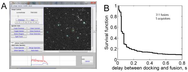
ACKNOWLEDGEMENTS
This work was supported by the CNRS and by an NIH grant to JER. EK is indebted to Michael Seagar and members of his laboratory (INSERM UMR641) for introducing him to proteoliposomes and Jeff Coleman (Yale University) for teaching him how to express and purify SNARE proteins. We thank Jean-Pierre Henry, François Darchen, and Bruno Gasnier (Laboratory of Membrane Dynamics and Neurological Diseases, CNRS/Université Paris Descartes UMR 8192, formerly CNRS UPR 1929), Thomas Melia and Andrea Gohlke (Dept. of Cell Biology, Yale University), Michael Power (School of Engineering and Applied Science clean room, Yale University), Ben O'Shaughnessy and Jason Warner at Columbia University for many useful discussions and suggestions, the CNRS for granting a leave of absence to EK, and Andrea Gohlke for help with some of the photos. We thank Andrea Gohlke, Weiming Xu, Bruno Antonny, Gregory Melikyan, Ben O'Shaughnessy, Jason Warner, and Jiajie Diao for carefully reading and commenting on the manuscript.
Footnotes
AUTHOR CONTRIBUTIONS
EK developed the assay first in the Laboratory of Membrane Dynamics and Neurological Diseases, CNRS/Université Paris Descartes UMR 8192 (formerly CNRS UPR 1929), then in the laboratory of JER at Yale University. JER oversaw the project and provided all the material support required since EK joined his lab. EK wrote the Matlab analysis programs that are supplied. EK wrote the manuscript, which was read and approved by JER.
COMPETING FINANCIAL INTERESTS
The authors declare that they have no competing financial interests.
REFERENCES
- 1.Weber T, et al. SNAREpins: minimal machinery for membrane fusion. Cell. 1998;92:759–72. doi: 10.1016/s0092-8674(00)81404-x. [DOI] [PubMed] [Google Scholar]
- 2.Sudhof TC, Rothman JE. Membrane fusion: grappling with SNARE and SM proteins. Science. 2009;323:474–7. doi: 10.1126/science.1161748. [DOI] [PMC free article] [PubMed] [Google Scholar]
- 3.Yoon TY, Okumus B, Zhang F, Shin YK, Ha T. Multiple intermediates in SNARE-induced membrane fusion. Proc Natl Acad Sci U S A. 2006;103:19731–6. doi: 10.1073/pnas.0606032103. [DOI] [PMC free article] [PubMed] [Google Scholar]
- 4.Kyoung M, et al. In vitro system capable of differentiating fast Ca2+-triggered content mixing from lipid exchange for mechanistic studies of neurotransmitter release. Proc Natl Acad Sci U S A. 2011;108:E304–13. doi: 10.1073/pnas.1107900108. [DOI] [PMC free article] [PubMed] [Google Scholar]
- 5.Diao J, et al. A single-vesicle content mixing assay for SNARE-mediated membrane fusion. Nat Commun. 1(54):2010. doi: 10.1038/ncomms1054. [DOI] [PMC free article] [PubMed] [Google Scholar]
- 6.Smith EA, Weisshaar JC. Docking, not fusion, as the rate-limiting step in a SNARE-driven vesicle fusion assay. Biophys J. 2011;100:2141–50. doi: 10.1016/j.bpj.2011.03.015. [DOI] [PMC free article] [PubMed] [Google Scholar]
- 7.Diao J, et al. A single vesicle-vesicle fusion assay for in vitro studies of SNAREs and accessory proteins. Nature Protocols. 2012 doi: 10.1038/nprot.2012.020. DOI: 10.1038/nprot.2012.020. [DOI] [PMC free article] [PubMed] [Google Scholar]
- 8.Karatekin E, et al. A fast, single-vesicle fusion assay mimics physiological SNARE requirements. Proc Natl Acad Sci U S A. 2010;107:3517–21. doi: 10.1073/pnas.0914723107. [DOI] [PMC free article] [PubMed] [Google Scholar]
- 9.Smith MB, et al. Interactive, computer-assisted tracking of speckle trajectories in fluorescence microscopy: application to actin polymerization and membrane fusion. Biophys J. 2011;101:1794–1804. doi: 10.1016/j.bpj.2011.09.007. [DOI] [PMC free article] [PubMed] [Google Scholar]
- 10.Brian AA, McConnell HM. Allogeneic stimulation of cytotoxic T cells by supported planar membranes. Proc Natl Acad Sci U S A. 1984;81:6159–63. doi: 10.1073/pnas.81.19.6159. [DOI] [PMC free article] [PubMed] [Google Scholar]
- 11.Tamm LK, McConnell HM. Supported phospholipid bilayers. Biophys J. 1985;47:105–13. doi: 10.1016/S0006-3495(85)83882-0. [DOI] [PMC free article] [PubMed] [Google Scholar]
- 12.Fix M, et al. Imaging single membrane fusion events mediated by SNARE proteins. Proc Natl Acad Sci U S A. 2004;101:7311–6. doi: 10.1073/pnas.0401779101. [DOI] [PMC free article] [PubMed] [Google Scholar]
- 13.Bowen ME, Weninger K, Brunger AT, Chu S. Single molecule observation of liposome-bilayer fusion thermally induced by soluble N-ethyl maleimide sensitive-factor attachment protein receptors (SNAREs) Biophys J. 2004;87:3569–84. doi: 10.1529/biophysj.104.048637. [DOI] [PMC free article] [PubMed] [Google Scholar]
- 14.Liu T, Tucker WC, Bhalla A, Chapman ER, Weisshaar JC. SNARE-driven, 25-millisecond vesicle fusion in vitro. Biophys J. 2005;89:2458–72. doi: 10.1529/biophysj.105.062539. [DOI] [PMC free article] [PubMed] [Google Scholar]
- 15.de Gennes PG. Polymers at an interface; a simplified view. Advances in Colloid and Interface Science. 1987;27:189–209. [Google Scholar]
- 16.Kenworthy AK, Hristova K, Needham D, McIntosh TJ. Range and magnitude of the steric pressure between bilayers containing phospholipids with covalently attached poly(ethylene glycol. Biophys J. 1995;68:1921–36. doi: 10.1016/S0006-3495(95)80369-3. [DOI] [PMC free article] [PubMed] [Google Scholar]
- 17.Milner ST. Polymer brushes. Science. 1991;251:905–14. doi: 10.1126/science.251.4996.905. [DOI] [PubMed] [Google Scholar]
- 18.Israelachvili J. The different faces of poly(ethylene glycol) Proc Natl Acad Sci U S A. 1997;94:8378–8379. doi: 10.1073/pnas.94.16.8378. [DOI] [PMC free article] [PubMed] [Google Scholar]
- 19.Oesterhelt F, Rief M, Gaub HE. Single molecule force spectroscopy by AFM indicates helical structure of poly(ethylene-glycol) in water. New Journal of Physics. 1999;1:6.1–6.11. [Google Scholar]
- 20.Perrret E, Leung A, Morel A, Feracci H, Nassoy P. Versatile decoration of glass surfaces to probe individual protein-protein interactions and cellular adhesion. Langmuir. 2002;18:846–854. [Google Scholar]
- 21.Knoll W, et al. Solid supported lipid membranes: New concepts for the biomimetic functionalization of solid surfaces. Biointerphases. 2008;3:Fa125–Fa135. doi: 10.1116/1.2913612. [DOI] [PMC free article] [PubMed] [Google Scholar]
- 22.Hiergeist C, Lipowsky R. Elastic properties of polymer-decorated membranes. Journal De Physique II. 1996;6:1465–1481. [Google Scholar]
- 23.Kenworthy AK, Simon SA, McIntosh TJ. Structure and phase behavior of lipid suspensions containing phospholipids with covalently attached poly(ethylene glycol) Biophys J. 1995;68:1903–20. doi: 10.1016/S0006-3495(95)80368-1. [DOI] [PMC free article] [PubMed] [Google Scholar]
- 24.Lasic DD, Needham D. The “Stealth” liposome: A prototypical biomaterial. Chemical Reviews. 1995;95:2601–2628. [Google Scholar]
- 25.Albertorio F, et al. Fluid and air-stable lipopolymer membranes for biosensor applications. Langmuir. 2005;21:7476–82. doi: 10.1021/la050871s. [DOI] [PubMed] [Google Scholar]
- 26.Tanaka M, Sackmann E. Polymer-supported membranes as models of the cell surface. Nature. 2005;437:656–63. doi: 10.1038/nature04164. [DOI] [PubMed] [Google Scholar]
- 27.Deng Y, et al. Fluidic and air-stable supported lipid bilayer and cell-mimicking microarrays. Journal of the American Chemical Society. 2008;130:6267–6271. doi: 10.1021/ja800049f. [DOI] [PMC free article] [PubMed] [Google Scholar]
- 28.Lin J, Szymanski J, Searson PC, Hristova K. Effect of a Polymer Cushion on the Electrical Properties and Stability of Surface-Supported Lipid Bilayers. Langmuir. 2010;26:3544–3548. doi: 10.1021/la903232b. [DOI] [PubMed] [Google Scholar]
- 29.Wong JY, et al. Polymer-cushioned bilayers. I. A structural study of various preparation methods using neutron reflectometry. Biophys J. 1999;77:1445–57. doi: 10.1016/S0006-3495(99)76992-4. [DOI] [PMC free article] [PubMed] [Google Scholar]
- 30.Cornell BA, et al. A biosensor that uses ion-channel switches. Nature. 1997;387:580–3. doi: 10.1038/42432. [DOI] [PubMed] [Google Scholar]
- 31.Deverall MA, et al. Transbilayer coupling of obstructed lipid diffusion in polymer-tethered phospholipid bilayers. Soft Matter. 2008;4:1899–1908. [Google Scholar]
- 32.Floyd DL, Ragains JR, Skehel JJ, Harrison SC, van Oijen AM. Single-particle kinetics of influenza virus membrane fusion. Proc Natl Acad Sci U S A. 2008;105:15382–7. doi: 10.1073/pnas.0807771105. [DOI] [PMC free article] [PubMed] [Google Scholar]
- 33.Kataoka-Hamai C, Higuchi M, Iwai H, Miyahara Y. Detergent-Mediated Formation of Polymer-Supported Phospholipid Bilayers. Langmuir. 2010;26:14600–14605. doi: 10.1021/la102151p. [DOI] [PubMed] [Google Scholar]
- 34.Daniel S, Albertorio F, Cremer PS. Making lipid membranes rough, tough, and ready to hit the road. Mrs Bulletin. 2006;31:536–540. [Google Scholar]
- 35.Diaz AJ, Albertorio F, Daniel S, Cremer PS. Double cushions preserve transmembrane protein mobility in supported bilayer systems. Langmuir. 2008;24:6820–6826. doi: 10.1021/la800018d. [DOI] [PMC free article] [PubMed] [Google Scholar]
- 36.Fasshauer D, Otto H, Eliason WK, Jahn R, Brunger AT. Structural changes are associated with soluble N-ethylmaleimide-sensitive fusion protein attachment protein receptor complex formation. J Biol Chem. 1997;272:28036–41. doi: 10.1074/jbc.272.44.28036. [DOI] [PubMed] [Google Scholar]
- 37.Hazzard J, Sudhof TC, Rizo J. NMR analysis of the structure of synaptobrevin and of its interaction with syntaxin. J Biomol NMR. 1999;14:203–7. doi: 10.1023/a:1008382027065. [DOI] [PubMed] [Google Scholar]
- 38.Bright JN, Woolf TB, Hoh JH. Predicting properties of intrinsically unstructured proteins. Progress in Biophysics & Molecular Biology. 2001;76:131–173. doi: 10.1016/s0079-6107(01)00012-8. [DOI] [PubMed] [Google Scholar]
- 39.Quinn P, Griffiths G, Warren G. Density of newly synthesized plasma membrane proteins in intracellular membranes II. Biochemical studies. J Cell Biol. 1984;98:2142–7. doi: 10.1083/jcb.98.6.2142. [DOI] [PMC free article] [PubMed] [Google Scholar]
- 40.Wessels L, Elting MW, Scimeca D, Weninger K. Rapid membrane fusion of individual virus particles with supported lipid bilayers. Biophys J. 2007;93:526–38. doi: 10.1529/biophysj.106.097485. [DOI] [PMC free article] [PubMed] [Google Scholar]
- 41.Brunger AT, Weninger K, Bowen M, Chu S. Single-molecule studies of the neuronal SNARE fusion machinery. Annu Rev Biochem. 2009;78:903–28. doi: 10.1146/annurev.biochem.77.070306.103621. [DOI] [PMC free article] [PubMed] [Google Scholar]
- 42.Domanska MK, Kiessling V, Stein A, Fasshauer D, Tamm LK. Single vesicle millisecond fusion kinetics reveals number of SNARE complexes optimal for fast SNARE-mediated membrane fusion. J Biol Chem. 2009;284:32158–66. doi: 10.1074/jbc.M109.047381. [DOI] [PMC free article] [PubMed] [Google Scholar]
- 43.Pobbati AV, Stein A, Fasshauer D. N- to C-terminal SNARE complex assembly promotes rapid membrane fusion. Science. 2006;313:673–6. doi: 10.1126/science.1129486. [DOI] [PubMed] [Google Scholar]
- 44.Needham D, Nunn RS. Elastic deformation and failure of lipid bilayer membranes containing cholesterol. Biophys J. 1990;58:997–1009. doi: 10.1016/S0006-3495(90)82444-9. [DOI] [PMC free article] [PubMed] [Google Scholar]
- 45.Rawicz W, Smith BA, McIntosh TJ, Simon SA, Evans E. Elasticity, strength, and water permeability of bilayers that contain raft microdomain-forming lipids. Biophys J. 2008;94:4725–36. doi: 10.1529/biophysj.107.121731. [DOI] [PMC free article] [PubMed] [Google Scholar]
- 46.Nikolaus J, Stockl M, Langosch D, Volkmer R, Herrmann A. Direct visualization of large and protein-free hemifusion diaphragms. Biophys J. 2010;98:1192–9. doi: 10.1016/j.bpj.2009.11.042. [DOI] [PMC free article] [PubMed] [Google Scholar]
- 47.Ohki S. A mechanism of divalent ion-induced phosphatidylserine membrane fusion. Biochim Biophys Acta. 1982;689:1–11. doi: 10.1016/0005-2736(82)90182-1. [DOI] [PubMed] [Google Scholar]
- 48.Berquand A, et al. Two-step formation of streptavidin-supported lipid bilayers by PEG-triggered vesicle fusion. Fluorescence and atomic force microscopy characterization. Langmuir. 2003;19:1700–1707. [Google Scholar]
- 49.Israelachvili JN. Intermolecular and surface forces. Academic Press; London: 1991. [Google Scholar]
- 50.Finkelstein A. Bilayers: formation, measurements, and incorporation of components. Methods Enzymol. 1974;32:489–501. doi: 10.1016/0076-6879(74)32049-6. [DOI] [PubMed] [Google Scholar]
- 51.Scott BL, et al. Liposome fusion assay to monitor intracellular membrane fusion machines. Methods Enzymol. 2003;372:274–300. doi: 10.1016/S0076-6879(03)72016-3. [DOI] [PubMed] [Google Scholar]
- 52.Wang T, Smith EA, Chapman ER, Weisshaar JC. Lipid mixing and content release in single-vesicle, SNARE-driven fusion assay with 1–5 ms resolution. Biophys J. 2009;96:4122–31. doi: 10.1016/j.bpj.2009.02.050. [DOI] [PMC free article] [PubMed] [Google Scholar]
- 53.Soumpasis DM. Theoretical analysis of fluorescence photobleaching recovery experiments. Biophys J. 1983;41:95–7. doi: 10.1016/S0006-3495(83)84410-5. [DOI] [PMC free article] [PubMed] [Google Scholar]
Associated Data
This section collects any data citations, data availability statements, or supplementary materials included in this article.