Abstract
Plasmon resonances are computed for nanoshells of prolate and oblate spheroidal shape. Both longitudinal and transverse resonances are investigated as a function of aspect ratio and shell thickness. Formulas for the surface charge density on the outside and inside shell surfaces are derived.
Index Terms: Nanotechnology, optical resonance, optical scattering, particle scattering, plasmons
I. INTRODUCTION
Plasmon resonances arise within a metallic nanoparticle from the collective oscillation of free electrons driven by an incident optical field. The plasmonic response of nanoparticles have played a role in a growing number of applications, including surface-enhanced Raman scattering (SERS), chemical sensing, drug delivery, photothermal cancer therapy and new photonic devices. Our laboratory has been involved in the investigation and application of plasmonics nanosubstrates for SERS detection for over two decades. Since our first report on the practical analytical use of the SERS techniques for the trace analysis of a variety of chemicals including several homocyclic and heterocyclic polyaromatic compounds in 1984 [1], our laboratory has been involved in the development of SERS technologies for applications in chemical sensing, biological analysis and medical diagnostics [2]–[8]. Our substrates involve nanoparticles and seminanoshells consisting of a layer of nanoparticles coated by silver on one side (halfshells).
Halas and collaborators have shown that plasmon resonances of spherical shells can be tuned by controlling the shell thickness [9]–[15]. These shells consist typically of a metallic layer over a dielectric core. In this report, we extend the analysis to spheroidal shells and show how plasmon resonances (both longitudinal and transverse modes) are influenced by both shell thickness and aspect ratio. A number of researchers have examined the plasmonic response of the solid spheroidal particle in their analysis of surface-enhanced Raman scattering [16]–[28], although the spheroidal shell appears not to have been investigated.
In this work, plasmon resonances are computed for nanoshells of prolate and oblate spheroidal shape. In our analysis, several simplifying assumptions have been made for the sake of tractability. It is assumed that the particles are much smaller than the optical wavelength, so that the incident electric field may be regarded as uniform over the dimensions of the particle. We thus employ the quasi-static approximation and derive only the dipole resonances (higher-order multipolar resonances are neglected). There is some evidence however, that the quadrapole response of (solid) spheroidal particles is much smaller than the dipole response [28]: this relative difference is less dramatic for spherical particles. We shall also neglect finite-size effects, such as radiation damping and phase-retardation effects, which become more important as the particle size approaches an optical wavelength. For very small particles, some resonance broadening is expected due to electron surface scattering as the particle size (or shell thickness) becomes smaller than the electron mean free path, although some evidence suggests that this is a less important contributor to broadening than particle size and shape inhomogeneities [14]. In our analysis, we shall not attempt to correct for these effects. Finally, we employ the Drude free-electron model for the frequency-dependence of the dielectric constant, given by
| (1) |
where ωp is the plasma frequency of the bulk material, γ is the width of the resonance and ε∞ is a constant assumed independent of ω as a first approximation. In view of the above assumptions, we expect only qualitative agreement with experimental results. Nonetheless, our analysis should be useful in exhibiting the general features of the resonance behavior of spheroidal shells relative to those of spherical shells. Our baseline for comparison will be the spherical shell. In the following, we derive expressions for the surface charge density induced by the incident electric field rather than, for example, an extinction cross section. The advantage of computing the charge density is that it is independent of the spheroid volume (unlike a cross section) and thus is more convenient for comparing spheroids with differing aspect ratios.
In deriving the response of the spheroidal shell, we resolve the incident electric field into two perpendicular components, one along the symmetry axis of the spheroid and the other perpendicular to this axis. The two cases are treated separately with the general response being a superposition of the two.
II. SPHEROIDAL COORDINATES AND BOUNDARY CONDITIONS
Consider a prolate spheroid centered at the origin with the z-axis along its major axis. Assume the two foci are at z = ±d. Then the prolate spheroidal coordinates are given by ([29], p. 1284)
| (2) |
| (3) |
| (4) |
where 1 ≤ ξ < ∞, 0 ≤ ϑ ≤ π and 0 ≤ ϕ ≤ 2π (often the equivalent variable η = cos ϑ is used). Evidently, ξ plays the role of the “radial” coordinate, ϑ is the spheroidal colatitude angle and ϕ is the azimuthal angle. The spheroidal coordinate ϑ is analogous to the spherical colatitude angle θ, and in the limit as ξ → ∞, ϑ tends toward θ. Setting ξ = ξ1 = constant defines the surface of a spheroid with a major semiaxis of length dξ1 and a minor semiaxis of length ; thus the two parameters d and ξ1 define its shape uniquely. For a prolate spheroid the aspect ratio is .
In the limit as the separation of the foci of the spheroid goes to zero (d → 0), the spheroid becomes a sphere and the spheroidal coordinates reduce to spherical coordinates. Evidently, as d → 0, then ξ1 → ∞ in such a way that dξ1 → a, the sphere radius, and ϑ → θ.
The gradient of a function, ψ(ξ, ϑ, ϕ), in spheroidal coordinates is given by
| (5) |
where ξ̂, ϑ̂ and ϕ̂ are the spheroidal unit vectors, and the metric scale factors for the prolate spheroidal system are and . As d → 0, one can show that hξ → d, hϑ → r, hϕ → r sin θ, ξ̂ → r̂ and ϑ̂ → θ̂, as expected. The corresponding relations for oblate spheroidal coordinates can be formally obtained by replacing d by −id and ξ by iξ. For the oblate spheroid defined by the parameters d and ξ1, the axial thickness of the spheroid is given by 2dξ1 and the equatorial radius is , where 0 < ξ < ∞. In this case the aspect ratio is .
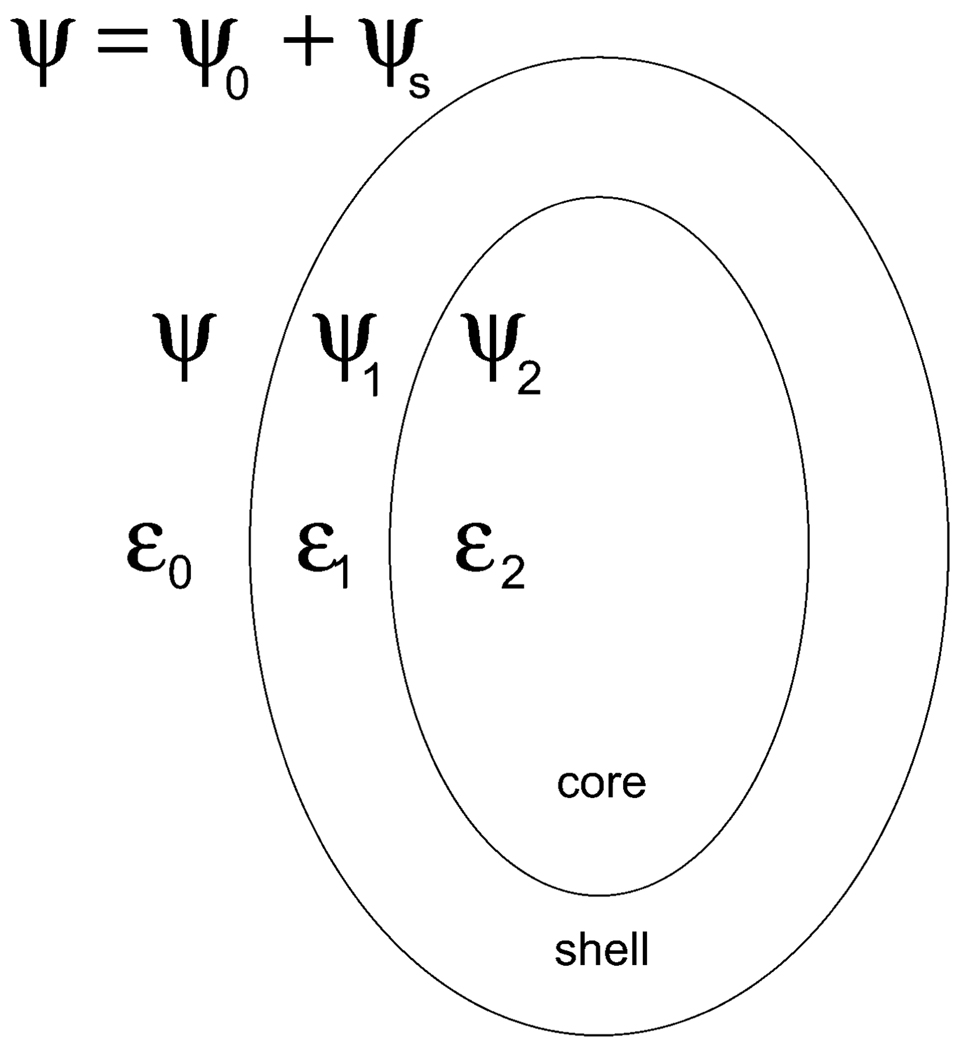
The electric field, E, in the quasi-static approximation can be expressed as the gradient of a potential ψ; that is, E = −∇ψ, where ψ is the solution to Laplace’s equation. The boundary conditions at each interface are continuity of the tangential component of E and continuity of the normal component of the displacement vector D = ε E. These conditions can be shown to be equivalent to the continuity of the potential ψ and ε ∂ψ/∂ξ across the interface. Let E0 denote the incident electric field and let ψ0 represent its associated potential, that is, E0 = −∇ψ0. Also, let the potentials ψs, ψ1, and ψ2 define the scattered field and the fields inside the spheroidal shell and core, respectively, and let ε0, ε1, and ε2 denote the dielectric constants external to the particle and inside the shell and core, as illustrated in Fig. 1. Letting ξ1 and ξ2 define the outer and inner shell boundaries, the boundary conditions are given by
| (6) |
| (7) |
| (8) |
| (9) |
where the prime means differentiation with respect to the spheroidal “radial” coordinate, ξ.
Fig. 1.
Spheroidal shell.
III. SOLUTIONS
A. Longitudinal Mode (Prolate Case)
Suppose the incident electric field is directed along the symmetry axis of the spheroid (always assumed to be the z-axis), that is, E0 = E0ẑ, where ẑ is a unit vector. The incident potential is then ψ0 = −E0z, which in spheroidal coordinates may be written in view of (4) as
| (10) |
The scattered potential, ψs, can be expressed as the following series solution to Laplace’s equation in spheroidal coordinates:
| (11) |
where η ≡ cos ϑ, and and are the Legendre functions of the first and second kind, and Rmn and Smn are constant coefficients. The Legendre functions can be expressed in terms of elementary functions (see Appendix). The axial symmetry of the spheroid implies that all m are zero, and (11) reduces to
| (12) |
Recalling that η = cos ϑ and using the relations in the Appendix, (10) can be written
| (13) |
In view of the orthogonality of the functions Pn(η) = Pn(cos ϑ), only the n = 1 term survives in the sum (12), giving for the scattering potential
| (14) |
where R is a constant. The potentials inside the shell and core will have the form
| (15) |
| (16) |
Substituting (13)–(16) into the boundary conditions (6)–(7), we obtain the following four equations for the coefficients R, A, B, and T:
| (17) |
| (18) |
| (19) |
| (20) |
Solving for R, A, B, and T, we obtain:
| (21) |
| (22) |
| (23) |
| (24) |
where
| (25) |
The identity was used in deriving the above expressions.
From these results, the induced surface charge density on the outer surface of the shell can be computed. This charge density is given by the jump in the normal component of the polarization vector just inside and outside of the surface [30].
| (26) |
where Pout = Dout − ε0Eout and Pin = Din − ε0Ein are the polarizations just inside and outside of the interface. In view of the boundary condition Dout · ξ̂ = Din · ξ̂ at the interface, this implies
| (27) |
Using the above results and the definition of the gradient given by (5), we obtain after some algebra
| (28) |
where recall . From this we see that the angular dependence of the surface charge density is of the form
| (29) |
where f(ξ1) is a function of ξ1 only. In the limit as ξ1 → ∞, the spheroid becomes a sphere and the angular dependence becomes cos θ. As expected, the magnitude of σL(θ) is a maximum on the ends of the spheroid (ϑ = 0) and vanishes on the sides of the spheroid transverse to the incident field (where ϑ = π/2). The charge density on the inner surface of spheroidal shell can be similarly calculated and is given by
| (30) |
Note the change in sign from (27) since the normal to the inner surface now points inward. After some algebra, we find
| (31) |
where with D given by (25).
In the limit as d → 0, the spheroidal shell reduces to a spherical shell and we can check that the surface charge density reduces to that of a spherical shell as d → 0. In this limit, the coordinates ξ1 and ξ2 go to infinity in such as way that ξ1d → r1 and ξ2d → r2, where r1 and r2 are the radii of the outer and inner spherical shell boundaries. The charge density (28) can be shown to reduce to the spherical case using the following large argument asymptotic forms of the Legendre functions: . We also note that hξ → d and ϑ → θ as d → 0. Making these substitutions in (28), we obtain the surface charge density induced on a spherical shell [see (32)]. This can be shown to agree with the spherical shell solution obtain Zhu et al. [31]. As another check on the analysis, we can verify that the above expressions for R, A, B, and T reduce to those for the solid spheroid after setting ε2 = ε1. In this case, one obtains A = 0, B = T, where now
and
Using the expressions for in the Appendix, these results can be shown to agree with those of Ishimaru [32] for a solid spheroid.
| (32) |
B. Transverse Mode (Prolate Case)
In this case the incident field, E0, is transverse to the spheroidal symmetry axis (now along the x-axis). Thus E0 = E0x̂ and the incident potential is ψ0 = −E0x, or in spheroidal coordinates using (2),
| (33) |
This may be equivalently written as (see Appendix)
| (34) |
Employing the boundary conditions, we find that in the sum (11) only the m = 1 and n = 1 terms survive and thus ψs is of the form
| (35) |
It also follows that the potentials in the shell and core are of the form
| (36) |
| (37) |
Substituting these potentials into the boundary conditions (6)–(9) yields a set of equations identical to (17)–(20) except that now are replaced everywhere by . See the Appendix for definitions of in terms of elementary functions.
The induced surface charge density on the outer surface of the shell for a transversely incident wave can again be computed from the jump in the normal component of the polarization vector just inside and outside of the surface as given by (26). The result is
| (38) |
where in this case
| (39) |
In deriving this, the identity was used. Once again, (38) can be shown to reduce to the surface charge density induced in a spherical shell when d → 0, given by (32), with the aid of the large argument forms .
C. Longitudinal Mode (Oblate Case)
The results for the oblate spheroid can be obtained directly from those of the prolate spheroid by replacing everywhere ξ with iξ and d with −id in the prolate formulas given above ([29], p. 1502). Thus, the surface charge density for the oblate spheroid for longitudinal incidence is given by
| (40) |
where
| (41) |
and in this case . Expressions for are given in the Appendix in terms of elementary functions.
D. Transverse Mode (Oblate Case)
For transverse incidence, we replace , which gives
| (42) |
where in this case
| (43) |
See the Appendix for expressions for .
IV. SIMULATIONS
In this section, we present calculations using the following values in (1) to define the free-electron dielectric constant: ε∞ = 3.71, ωp = 9.21 eV and γ = 0.087 eV. These are bulk values for silver obtained by fitting (1) to the data of Johnson and Christy [33]. These values are close to but not identical to the values obtained by Oubre and Nordlander from the same data set [34]. In these calculations, we set the core permittivity to that of silica: ε2 = 4.5.
A. Prolate Resonances as a Function of Aspect Ratio
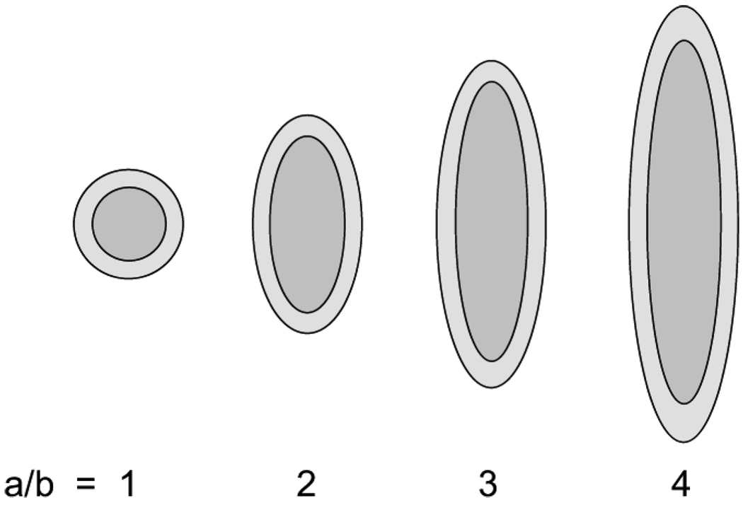
The plasmon resonances of a prolate shell were computed with different aspect ratios and compared to the resonance of a spherical shell. In these calculations, the shell thickness is 10% of the inner shell dimensions. Recall that ξ1 and ξ2 are the spheroidal “radial” coordinates that define, respectively, the outer and inner shell boundaries. We define a 10% shell thickness by setting ξ1 = 1.1 ξ2 in the above equations. The charge density was computed for four aspect ratios a/b equal to 1 (a sphere), 2, 3, and 4, which are labeled with these numbers in the following plots. The spheroid shapes are illustrated in Fig. 2.
Fig. 2.
Shells of aspect ratios equal to a/b = 1 (sphere), 2, 3, and 4.
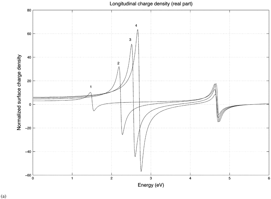
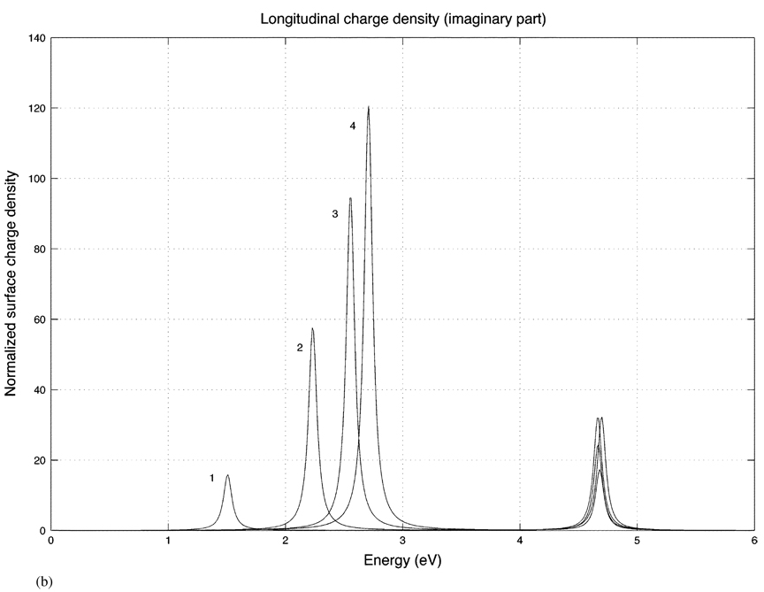
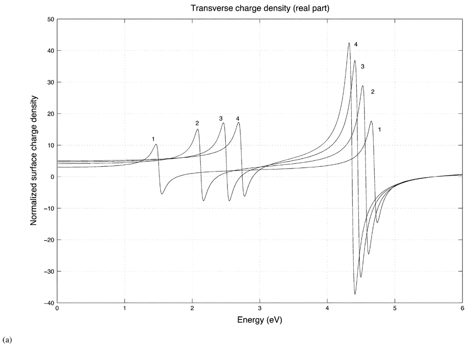
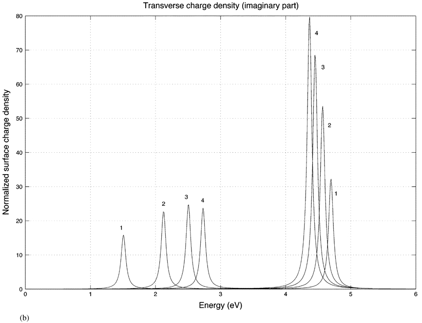
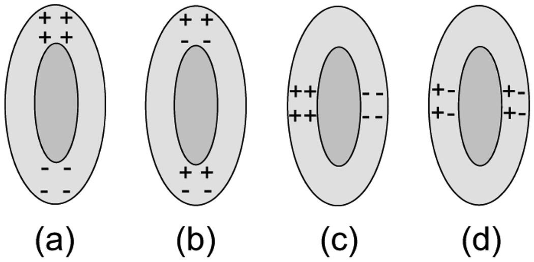
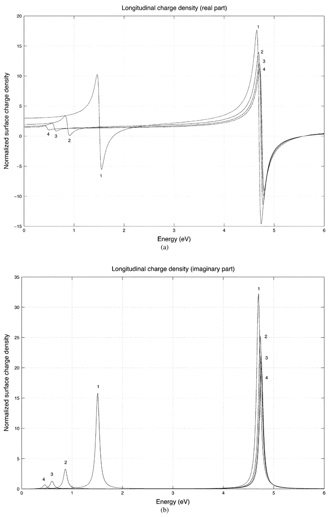
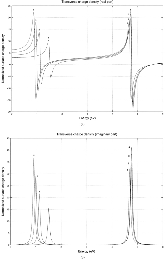
Fig. 3(a) and (b) show the real and imaginary parts of the induced surface charge density at the ends of the prolate spheroid (ϑ = 0) for a longitudinally incident electric field. For this direction of incidence, the peak magnitude of the charge density occurs at the two ends of the spheroidal shell. Fig. 4(a) and (b) show the real and imaginary parts of the surface charge density for a transversely incident electric field evaluated at ϑ = 90°, which is the region on the surface of maximum charge density for this direction of incidence. The double peak in the spectra corresponds to two eigenmodes, which is consistent with the description given previously by Radloff and Halas [13] in their work on spherical shells. The resonances of different energies physically correspond to the different charge distributions on the inner and outer shell interfaces, as illustrated in Fig. 5(a) and (b) for a longitudinally incident electric field. Fig. 5(a) and (b) correspond to the lower and higher energies, respectively. Note that the higher energy resonance is a feature of the shell and does not arise in the solid spheroid. The spectra also become sharper as the aspect ratio of the prolate shell increases due to the increasing curvature of the spheroid tip which gives rise to an increasing charge density there.
Fig. 3.
(a) Real part of the surface charge density for prolate spheroidal shells for a longitudinally incident field with the aspect ratios 1 (sphere), 2, 3, and 4. The charge density is evaluated at the end (ϑ = 0°) of the shell.
(b) Imaginary part of prolate longitudinal response.
Fig. 4.
(a) Real part of the surface charge density for prolate spheroidal shells for a transversely incident field with the aspect ratios 1 (sphere), 2, 3, and 4. The charge density is evaluated at the side (ϑ = 90°) of the shell.
(b) Imaginary part of the prolate transverse response.
Fig. 5.
Surface charge distributions for a longitudinally incident electric field [(a) and (b)] and a transversely incident electric field [(c) and (d)]. The lower-energy modes are (a) and (c) and the higher energy modes are (b) and (d).
B. Oblate Resonances as a Function of Aspect Ratio
Fig. 6(a) and (b) show the surface-charge densities of an oblate shell with a longitudinally incident electric field. Again real and imaginary parts are shown separately and in each plot the aspect ratio a/b are labeled as 1 (sphere), 2, 3, and 4. Fig. 6(a) and (b) show the real and imaginary parts of the charge density evaluated on the blunt end (ϑ = 0) of the oblate shell for a longitudinally incident electric field. Fig. 7(a) and (b) show the real and imaginary parts of the charge density on the equatorial edge (ϑ = 90°) of the oblate spheroid for a transversely incident electric field. For the case of a longitudinally incident field, the decreasing resonance magnitude with increasing aspect ratio on the blunt end of the oblate shell is consistent with the results of Kelly et al. [28] in their study of the spectra of solid oblate spheroids. In particular, this is true for the lower energy resonance, which corresponds to the charge distribution of a solid spheroid.
Fig. 6.
(a) Real part of the surface charge density for oblate spheroidal shells for a longitudinally incident field with the aspect ratios 1 (sphere), 2, 3, and 4. The charge density is evaluated on the blunt end (ϑ = 0°) of the shell. (b) Imaginary part of the oblate longitudinal response.
Fig. 7.
(a) Real part of the surface charge density for oblate spheroidal shells for a transversely incident field with the aspect ratios 1 (sphere), 2, 3, and 4. The charge density is evaluated on the equatorial edge (ϑ = 90°) of the shell. (b) Imaginary part of the oblate transverse response.
C. Prolate Resonances as a Function of Shell Thickness
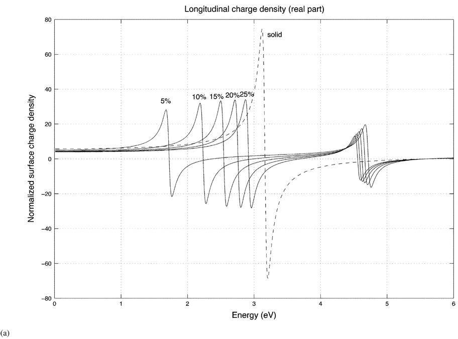
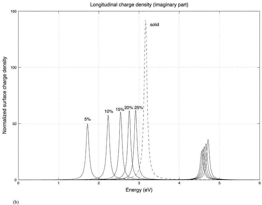
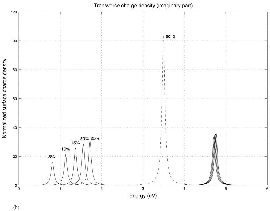
Fig. 8 shows the charge densities of a prolate shell for a fixed aspect ratio (2 to 1) and the different shell thicknesses of 5%, 10%, 15%, 20% and 25%. The dashed curve is the charge density of a solid spheroid (ε2 = ε1). Fig. 8(a) and (b) show the real and imaginary parts of the charge density evaluated at one end (ϑ = 0) of the prolate shell for a longitudinally incident electric field. Note that the lower energy resonances [corresponding to the charge distribution of Fig. 5(a)] shift to lower energies as the shell gets thinner. This should be expected since charges of the same sign coexist on the inner and outer shells and, due to electrostatic repulsion, the surface charge density decreases in this case. For the higher energy resonances [Fig. 5(b)], the opposite occurs since the charges on the inner and outer surfaces are of opposite sign, which tends to increase the charge density as the shell becomes thinner.
Fig. 8.
(a) Real part of the surface charge density for prolate shells of differing shell thicknesses (5%, 10%, 15%, 20%, 25%) with a fixed aspect ratio (2 to 1) for a longitudinally incident field. The dashed curve is the charge density of the solid prolate spheroid. In each case, the charge density is evaluated at the blunt end (ϑ = 0°) of the shell.
(b) Imaginary part of the prolate longitudinal response for different shell thicknesses.
D. Oblate Resonances as a Function of Shell Thickness
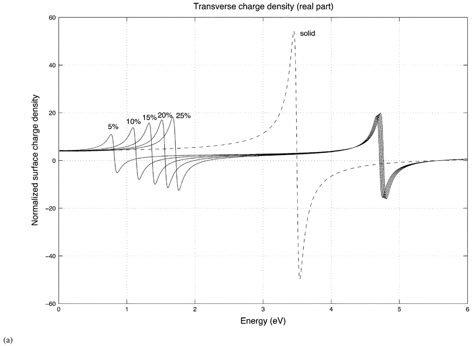
Fig. 9 shows the spectrum of an oblate spheroidal shell for a fixed aspect ratio (2 to 1) and the different shell thicknesses of 5%, 10%, 15%, 20%, and 25%. Fig. 9(a) and (b) display the real and imaginary parts of the charge density evaluated on the equatorial edge (ϑ = 90°) of the oblate shell and the solid oblate spheroid (dashed curve) for a transversely incident electric field.
Fig. 9.
(a) Real part of the surface charge density for oblate shells of differing shell thicknesses (5%, 10%, 15%, 20%, 25%) with a fixed aspect ratio (2 to 1) for a transversely incident field. The dashed curve is the charge density of the solid oblate spheroid. In each case, the charge density is evaluated on the equatorial edge (ϑ = 90°) of the shell.
(b) Imaginary part of the oblate transverse response for different shell thicknesses.
V. CONCLUSION
Our analysis of prolate and oblate spheroidal shells shows some interesting qualitative features in their plasmon resonances. We have chosen to compute the surface charge density rather than, for example, an extinction cross section, since the charge density is invariant with respect to the volume of the shell, whereas a cross section calculation depends on the particle’s volume. For a proper comparison of cross sections of shells with differing aspect ratios, a volume normalization would be needed. As Halas and collaborators have pointed out, one parameter, the shell thickness of a spherical nanoshell, can be used to tune the plasmon resonance frequency [13]. The results of our work indicate that the spheroidal shell presents two degrees of freedom for tuning: the shell thickness and the shell aspect ratio.
Acknowledgments
This work was sponsored in part by the National Institutes of Health under Grant R01 EB006201 and in part by the Department of Justice.
APPENDIX
LEGENDRE FUNCTIONS
We list here a number of useful properties of Legendre functions. are Legendre function of the first kind and are Legendre functions of the second kind. When ξ ≥ 1,
| (A44) |
| (A45) |
When the argument is real and confined to −1 ≤ x ≤ 1, we have (see [35], p. 333). The second-kind Legendre functions, , can be expressed in terms of elementary functions as follows ([29], p. 1327):
| (A46) |
| (A47) |
The derivatives of these functions with respect to ξ are
| (A48) |
| (A49) |
| (A50) |
| (A51) |
For large argument, the asymptotic forms for these functions are: .
For oblate spheroids, we replace ξ with iξ in the arguments of the Legendre functions. With the help of the relation ln[(iξ + 1)/(iξ − 1)] = −2i tan−1(1/ξ), we obtain
| (A52) |
| (A53) |
| (A54) |
| (A55) |
| (A56) |
| (A57) |
| (A58) |
| (A59) |
Contributor Information
Stephen J. Norton, Fitzpatrick Institute for Photonics, Duke University, Durham, NC 27708 USA.
Tuan Vo-Dinh, Fitzpatrick Institute for Photonics, the Department of Biomedical Engineering, and Department of Chemistry, Duke University, Durham, NC 27708 USA..
REFERENCES
- 1.Vo-Dinh T, Hiromoto MYK, Begun GM, Moody RL. Surface-enhanced raman spectroscopy for trace organic analysis. Anal. Chem. 1984;vol. 56:1667–1670. [Google Scholar]
- 2.Vo-Dinh T, Miller GH, Bello J, Johnson R, Moody RL, Alak A, Fletcher WH. Surface-active substrates for raman and luminescence analysis. Talanta. 1989;vol. 36:227–234. doi: 10.1016/0039-9140(89)80100-6. [DOI] [PubMed] [Google Scholar]
- 3.Vo-Dinh T. SERS chemical sensors and biosensors: New tools for environmental and biological analysis. Sens. Actuators B. 1995;vol. 29:183–189. [Google Scholar]
- 4.Vo-Dinh T, Houck K, Stokes DL. Surface-enhanced raman gene probes. Anal. Chem. 1995;vol. 66:3379–3383. doi: 10.1021/ac00092a014. [DOI] [PubMed] [Google Scholar]
- 5.Vo-Dinh T. Surface-enhanced raman spectroscopy using metallic nanostructures. Trends Anal. Chem. 1998;vol. 17:557–582. [Google Scholar]
- 6.Vo-Dinh T, Stokes DL. Surface-enhanced raman detection of chemical vapors and aerosols using personal dosimeters. Field Anal. Chem. Technol. 1999;vol. 3:346. [Google Scholar]
- 7.Vo-Dinh T, Allain LR, Stokes DL. Cancer gene detection using surface-enhanced raman scattering (SERS) J. Raman Spectrosc. 2002 Jul.vol. 33(no. 7):511–516. [Google Scholar]
- 8.Wabuyele M, Vo-Dinh T. Detection of HIV type 1 DNA sequence using plasmonics nanoprobes. Anal. Chem. 2005;vol. 77:7810–7815. doi: 10.1021/ac0514671. [DOI] [PubMed] [Google Scholar]
- 9.Averitt RD, Sarkar D, Halas NJ. Plasmon resonance shifts of au-coated au2s nanoshells: Insight into multicomponent nanoparticle growth. Phys. Rev. Lett. 1997;vol. 78:4217–4220. [Google Scholar]
- 10.Oldenburg SJ, Hale GD, Jackson JB, Halas NJ. Light scattering from dipole and quadrapole nanoshell antennas. Appl. Phys. Lett. 1999;vol. 75:1063–1065. [Google Scholar]
- 11.Westcott SL, Jackson JB, Radloff C, Halas NJ. Relative contributions to the plasmon line shape of metal nanoshells. Phys. Rev. B. 2002;vol. 66:155431-1–155431-5. [Google Scholar]
- 12.Jackson JB, Westcott SL, Hirsch LR, West JL, Halas NH. Controlling the surface enhanced raman effect via the nanoshell geometry. Appl. Phys. Lett. 2003;vol. 82:257–259. [Google Scholar]
- 13.Radloff C, Halas NH. Plasmonic properties of concentric nanoshells. Nano Lett. 2004;vol. 4:1323–1327. [Google Scholar]
- 14.Nehl CL, Grady NK, Goodrich GP, Tam F, Halas NJ, Hafner JH. Scattering spectra of single gold nanoshells. Nano Lett. 2004;vol. 4:2355–2359. [Google Scholar]
- 15.Tam F, Moran C, Halas N. Geometrical parameters controlling sensitivity of nanoshell plasmon resonances to changes in dielectric environment. J. Phys. Chem. B. 2004;vol. 108:17290–17294. [Google Scholar]
- 16.Gersten JI, Nitzan A. Electromagnetic theory of enhanced raman scattering by molecules adsorbed on rough surfaces. J. Chem. Phys. 1980;vol. 73:3023–3037. [Google Scholar]
- 17.Gersten JI. The effect of surface roughness on surface enhanced raman scattering. J. Chem. Phys. 1980;vol. 72:5779–5780. [Google Scholar]
- 18.Gersten JI, Rayleigh Mie and raman scattering by molecules absorbed on rough surfaces. J. Chem. Phys. 1980;vol. 72:5780–5781. [Google Scholar]
- 19.Adrian FJ. Surface enhanced raman scattering by surface plasmon enhancement of electromagnetic fields near spheroidal particles on a roughened metal surface. Phys. Lett. 1981;vol. 78:45–49. [Google Scholar]
- 20.Wang DS, Kerker M. Enhanced raman scattering by molecules adsorbed at the surface of colloidal spheroids. Phys. Rev. B. 1981;vol. 24:1777–1790. [Google Scholar]
- 21.Wokaun A, Gordon JP, Liao PF. Radiation damping in surface-enhanced raman scattering. Phys. Rev. Lett. 1982 Apr.vol. 48(no. 14):957–960. [Google Scholar]
- 22.Liao PF, Wokaun A. Lightning rod effect in surface enhanced raman scattering. J. Chem. Phys. 1982;vol. 76:751–752. [Google Scholar]
- 23.Barber PW, Chang RK, Massoudi H. Surface-enhanced electric intensities on large silver spheroids. Phys. Rev. Lett. 1983;vol. 50:997–1000. [Google Scholar]
- 24.Barber PW, Chang RK, Massoudi H. Electrodynamic calculations of the surface-enhanced electric intensities on large ag spheroids. Phys. Rev. B. 1983;vol. 27:7251–7261. [Google Scholar]
- 25.Schatz GC. Theoretical studies of surface enhanced raman scattering. Acc. Chem. Res. 1984;vol. 17:370–376. [Google Scholar]
- 26.Aroca R, Martin F. Tuning metal island films for maximum surface-enhanced raman scattering. J. Raman Spect. 1985;vol. 16:156–162. [Google Scholar]
- 27.Zeman EJ, Schatz GC. An accurate electromagnetic theory study of surface enhancement factors for Ag, Au, Cu, Li, Na, Al, Ga, In, Zn and Cd. J. Phys. Chem. 1987;vol. 91:634–643. [Google Scholar]
- 28.Kelly KL, Coronade E, Zhao LL, Schatz GC. The optical properties of metal nanoparticles: The influence of size, shape and dielectric environment. J. Phys. Chem. B. 2003;vol. 107:668–677. [Google Scholar]
- 29.Morse PM, Feshbach H. Methods of Theoretical Physics, Part I and II. New York: McGraw-Hill; 1953. [Google Scholar]
- 30.Corson DR, Lorrain P. Introduction to Electromagnetic Fields and Waves. San Francisco, CA: Freeman; 1962. [Google Scholar]
- 31.Zhu J, Wang Y, Huang L, Lu Y. Resonance light scattering characters of core-shell structure of au-ag nanoparticles. Phys. Lett. 2004;vol. 323:455–459. [Google Scholar]
- 32.Ishimaru A. Electromagnetic Propagation, Radiation and Scattering. Englewood Cliffs, NJ: Prentice-Hall; 1991. ch. 10. [Google Scholar]
- 33.Johnson PB, Christy RW. Optical constants of the noble metals. Phys. Rev. B. 1972 Dec.vol. 6(no. 12):4370–4379. [Google Scholar]
- 34.Oubre C, Nordlander P. Finite difference time domain studies of optical properties of nanoshell structures; Proc. SPIE; Aug. 2004; Plasmonics: Metallic Nanostructures and Their Optical Properties; pp. 133–143. [Google Scholar]
- 35.Abramowitz M, Stegun IA, editors. Handbook of Mathematical Functions. New York: Dover; 1965. [Google Scholar]


