Abstract
A large spectrum of medical devices exists; it aims to correct deformities associated with spinal disorders. The development of a detailed volumetric finite element model of the osteoligamentous spine would serve as a valuable tool to assess, compare, and optimize spinal devices. Thus the purpose of the study was to develop and initiate validation of a detailed osteoligamentous finite element model of the spine with simulated correction from spinal instrumentation. A finite element of the spine from T1 to L5 was developed using properties and geometry from the published literature and patient data. Spinal instrumentation, consisting of segmental translation of a scoliotic spine, was emulated. Postoperative patient and relevant published data of intervertebral disc stress, screw/vertebra pullout forces, and spinal profiles was used to evaluate the models validity. Intervertebral disc and vertebral reaction stresses respected published in vivo, ex vivo, and in silico values. Screw/vertebra reaction forces agreed with accepted pullout threshold values. Cobb angle measurements of spinal deformity following simulated surgical instrumentation corroborated with patient data. This computational biomechanical analysis validated a detailed volumetric spine model. Future studies seek to exploit the model to explore the performance of corrective spinal devices.
1. Introduction
Computational analyses, such as finite element modeling, have benefited from the ever-growing performance of computers allowing them to reliably simulate the complex biomechanical behavior of the musculoskeletal system. Moreover, this platform allows for a cost and time effective manner in which head-to-head device comparison may be objectively conducted. However, this mathematically complex form of analysis must be performed and interpreted with caution.
With regard to modeling of the spine, the last ten years have seen an influx of published models exploring spinal biomechanics. Using volumetric and rigid body models, Aubin et al. have pioneered work in the understanding of the pathomechanism of scoliosis [1–5], the mechanics of spondylolisthesis [6], the correction forces offered during scoliotic brace treatment [7–9], and the performance of next generation of minimally invasive growth modulation devices [10, 11]. Using rigid body models, Aubin et al. also simulated many times the surgical correction of spinal deformities via the introduction of rods and screw [12, 13] while others followed suit [14–16]. The aforementioned rigid body models use multilinear elastic beams and cables as a simplified spinal geometry and are at times constructed based on accurate 3D reconstructions from patient geometry [17]. A potential fallback of rigid body modeling and patient based construction is that analyses of internal stress distributions and hypothetical cases, without the support of actual patient data, cannot be easily explored. These shortcomings make optimization analyses, which explore a spectrum of hypothetical scenarios to derive reliable biomechanical insight, very cumbersome. On the opposite, detailed finite element modeling of the spine allows for more complete assessments of internal stress distribution within the model physiological tissue and instrumentation construct. Unfortunately, there is currently no available finite element model of the complete spine that can simulate the surgical correction of spinal disorders, as detailed FEM involving spinal instrumentation is limited to short segments of the spine.
The purpose of this preliminary study was to develop a parametric volumetric detailed finite element model of the osteoligamentous spine to simulate surgical corrections of common spinal pathologies which, in subsequent studies, will serve to compare, design, and optimize new spinal devices.
2. Material and Methods
2.1. Finite Element Model
A detailed custom finite element model (FEM) was coded using ANSYS APDL language (ANSYS 13.0 APDL, Canonsburg, PA). User input defines the 6 degrees of freedom and volumetric scale between subsequent adjacent vertebral bodies which, as a result of the constructive geometric overlay of the vertebrae and intervertebral disc, afford the user complete control over the end results spinal profile in all anatomical planes. The intervertebral discs were attributed to a modulus of elasticity of 8 MPa and 2 MPa [18]. The anterior longitudinal, posterior longitudinal, interspinous, ligamentum flavum, and capsular ligaments were modeled providing tensional forces defined by 23.75, 26.15, 9.8, 22.6, and 23.7 Newtons per mm of deformation, respectively, [19]. The vertebral bodies were modeled as rigid bodies. The superior surface of T1 was translationally constrained in the transverse plane while the inferior surface of L5 was allowed only coronal rotation.
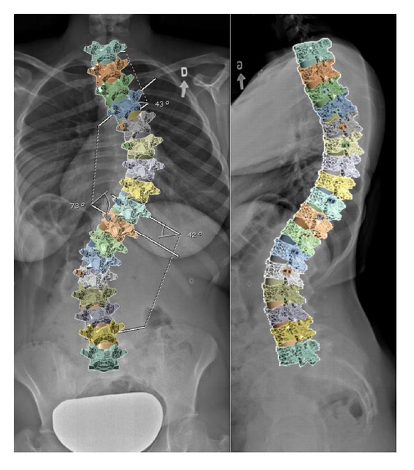
The selected patient to model had a scoliotic curve defined by a primary right thoracic Cobb angle of 73° and a proximal thoracic Cobb angle of 42° (Lenke type 2B). Lateral bending tests revealed the primary curvature to correct to 40° or by 45%. Postoperative radiographs showed the spine to correct to 20° or by 73%. The sagittal profile of the patient was defined by a pre- and postoperative thoracic kyphoses of 35° and 26° between T1 and T12, respectively, and a corresponding lumbar lordosis of 37° and 36° between L1 and L5. The model was constructed to represent the patient's spinal profile within 5° (Figure 1). Surgical correction was made by instrumenting the concave side of the curve using pedicle screws from T3–T6 and T9-L1 connected by a 5.5 mm diameter rod. A convex rod was used to stabilize the construct.
Figure 1.

Coronal and sagittal radiographs (thoracic curve 73°, kyphosis 35°, and lordosis 37°) and superimposed FEM (thoracic curve 69°, kyphosis 32°, and lordosis 36°).
Titanium (Ti-6Al-4V, grade 5) pedicle screws and the cobalt chrome rod had a modulus of 11 and 213 GPa, respectively. Contact between the screw shaft and the intervertebral body was programmed by coupling neighbouring element/nodes. The polyaxial screw head was simulated with a restricted outwardly conic degree of freedom of 60° governing the angle at which the rod was permitted to be captured within the screw head. The 5.5 mm spinal rod was shaped with respect to the desired sagittal profile.
2.2. Simulation of Surgical Steps
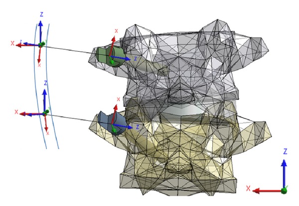
Segmental translation of the concave rod was simulated using several superimposed steps. Stabilization rod was not modeled. All bodies were assigned numerous coordinate systems centered to their geometric center of mass to control and measure movement. An artificial linkage was provided between every screw head and the spinal rod to reduce the distance between them in a controlled manner. This linkage consisted of several coordinate systems each with its own custom coded degrees of freedom (Figure 2). A first joint was fixed to the center of the screw head and allowed to translate along the z-axis which was aligned parallel to the second joint of the linkage located on the spinal rod. The second joint was free to rotate along its z- and y-axes and had a coordinate system located at the cross-sectional center of the rod and whose x-axis was tangentially aligned to the spinal rod profile. A third joint, which nested and shared origins with the second joint, was free to translate and rotate with respect to its z-axis which was aligned parallel to the global or axial axis of the spine. As needed, stiff bushings were introduced into the first joint to encourage convergence.
Figure 2.

Example of artificial linkage coordinates systems between screw heads and spinal rod.
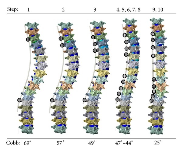
Surgical simulation began with the most cranial (T3) and caudal (L1) screws being housed with the rod and having linkages permitting axial rotation and translation (third joint z-axis) and only axial rotation (third joint z-axis, Figure 3, step 1) representing the set screw not being completely tightened. The distance between the screw head and rod was then subsequently reduced along the z-axis of the first joint moving from cranial (T4) to caudal (T12) (Figure 3, steps 3–8). Next, the rod was fixed in position while permitting translation and rotation in the global axial plane (third joint z-axis) while the most caudal screw L1 allowed only rod rotation. Finally, the rod was rotated until the predetermined spinal profile was found in the sagittal plane (Figure 3, step 9) and screw secured (Figure 3, step 10).
Figure 3.

Simulated surgical steps of segmental translation and spinal rod derotation of a scoliotic spine (circles filled with longitudinal, horizontal, and checkered graphics represent translation/rotation, rotation only, and fixed degrees of freedom of rod within screw heads, resp.).
2.3. Validation
Intervertebral disc stresses were continuously monitored and reviewed for adherence to in silico, ex vivo, and in vivo published data. Pullout forces measured at the screw/vertebra interface were also monitored and compared to relevant prior studies using biomechanical validated models simulating corrective scoliotic surgeries and to found threshold values suggesting risk of failure [20–22]. Postoperative curvatures from patient data and predicted values of the model, in terms of spinal profiles, were also compared to evaluate the reliability of the computational reactions of the model when imposed to comparable surgical instrumentation and maneuvers as performed in practice.
3. Results
The final FEM of the thoracic and lumbar spine instrumented on the concave side consisted of 66 volumetric bodies, 33 contact regions, 96 tension only elements (ligaments), and 43 joints. Measures of intervertebral disc stress (von-Mises) were maintained within acceptable values as reported in Table 1. These measures represent the average stress measured in the entire disc over the course of the surgical simulation for discs not being spanned by instrumentation (i.e., between T1–T3, T6–T9, and L1–L5). Measures of stress in intervertebral discs found between instrumented vertebrae averaged at stress of 3.95 MPa over the entire simulation of the surgical procedure. No consistent correlation between peak measures of intervertebral disc stress and the simulated surgical maneuver was observed.
Table 1.
Published in vivo, ex vivo, and in silico values of intervertebral disc stresses.
| Author | Method | Disc Location | Disc Section | Mean stress (MPa) |
|---|---|---|---|---|
| Adams 1996 [23] | Ex vivo | L4-5 | Nucleus | 1.6 |
| Anterior | 2 | |||
| Posterior | 2.6 | |||
| Wilke 1999 [24] | In vivo sanding | L4-5 | Nucleus | 0.5 |
| Schultz 1982 [25] | In vivo sanding | L4-5 | Nucleus | 0.27 |
| Nachemson 1965 [26] | In vivo standing | L4-5 | Nucleus | 0.87 |
| Andersson 1974 [27] | Computational | L4-5 | Nucleus | 0.3–0.5 |
| Meir 2007 [28] | In vivo lateral | Apex | Concave | 0.8–0.4 |
| Convex | 0.15 | |||
| Sato 1999 [29] | In vivo prone | L4-5 | Nucleus | 0.15 |
| Shrzypiec 2007 [30] | Ex vivo | C7-T1 | Nucleus | 1 |
| Anterior | 1.35 | |||
| Posterior | 1.1 | |||
| Steffen 1998 [31] | Ex vivo | L3-4 | Nucleus | 0.8 |
| Schroeder 2006 [32] | FEM | L4-5 | Nucleus | 0.6–0.85 |
| Anterior | 0.6–1 | |||
| Posterior | 0.8–1.2 | |||
| Current Study | FEM | T1–T3 | Average | 0.59 |
| T6–T9 | 2.56 | |||
| L1–L5 | 0.81 |
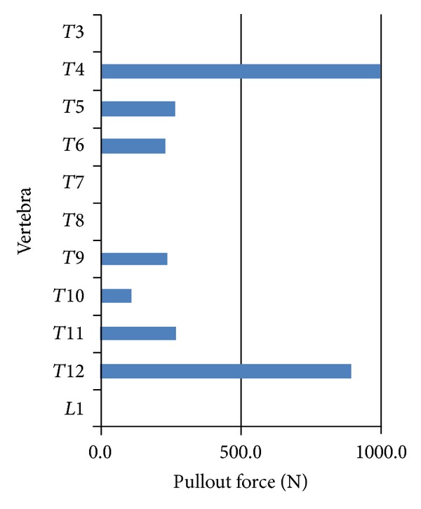
Pullout forces acquired at the screw/vertebra interface of all pedicle screws are reported in Figure 4. Most commonly, in five of seven screws (T3–T5, T9, and T11), the peak screw pullout force was experienced during the initial rod capture. Otherwise peak pullout was experienced during the simulated rod derotation maneuver (T10 and T12). In screws having their peak pullout during initial capture, the common force pullout versus surgical step graph resembled that of T6 exemplified in Figure 5. In this scenario, T6 pullout forces peaked when the concave screw was joined to the rod (Figures 3 and 5, step 3) and then reduced during subsequent steps during which the rod was attached to the subsequent screw heads (Figures 3 and 5, steps 4–10).
Figure 4.

Maximum pullout forces measured during the simulation for each vertebra.
Figure 5.

Pullout forces at T6 during simulated segmental translation of scoliotic spine model.
Spinal profiles adhered to patient data within the instrumented thoracic and lumbar regions of the model within the targeted 5°. The postoperative thoracic Cobb angles from patient and simulated data were 20° and 25° while the kyphoses were 26° and 28° respectively. Outside the instrumentation in the lumbar region the postoperative lordosis was measured at 36° and 30° for patient and simulated data correspondingly. To achieve this corroborative data the mechanical properties of the intervertebral disc annuli were adapted to 5 MPa. The primary thoracic Cobb angle of the model was reduced after each iteration of the simulated surgical steps as detailed in Figure 3. Steps 4–8 saw little in scoliotic reduction of the Cobb angles as the rod had little to travel to be secured to the screw heads. Maximum correction of the thoracic Cobb angle was experienced during the simulation of the rod derotation maneuver, step 9, when it reduced from 44° to 25°.
4. Discussion
This study utilized a custom coded parametric and volumetric model of the osteoligamentous thoracic and lumbar spine to simulate common surgical techniques used in the correction of scoliotic spines. Stresses measured in the intervertebral discs not spanning an instrumented segment are consistent with the published literature. Discs that spanned instrumented vertebrae showed an average stress higher than such a range perhaps due to local manipulation and/or compressions introduced by the simulated surgical processes.
Pullout forces measured at the screw/vertebra interface were in agreement with relevant computational models. Wang et al., in a well-performed study, explored the pullout forces using both monoaxial and a multidegree of freedom postloading screws and reported forces up to 886 Newtons [13]. Aubin et al. found pullout forces from simulated up to 1073 Newtons [12]. Complementing FEM studies of pedicle screw pullout documented between 1218 to 1892 Newtons [20]. Results of pullout forces experience in the developed model were well within these ranges suggesting that simulated reaction forces were sound.
Coupling the simulated spine model profile to the patient data required modification to intervertebral disc material properties causing successful corroboration within the instrumented region. This is due to accurately modeled mathematical relations between the vertebrae, screws, and the spinal rod. Outside the instrumented area, the lumbar spine had less accuracy. This resides with difficulties to simulate response of the spine outside the instrumentation region which depends on secondary reactions from overhead simulated surgical maneuvers.
The model proposes a novel in silico platform offering a means to explore new medical devices for the treatment of spinal pathologies. A number of assumptions must be considered when seeking to extract concrete insight. The variability within the mechanical behavior of physiological tissue can hinder any models conclusions, such as those governing the response of the noninstrumented curve. Alternative studies, given the strict parameterization of the model, could easily compare, as an example, influence of utilizing different rod materials, use of other anchors (hooks and wires) and correction maneuvers such as compression, distraction, segmental derotation, and/or in situ bending.
This preliminary validated model of the spine allows one to monitor the intervertebral disc stresses and screw pullout forces over the course of the simulated surgery. The models purpose is to provide insight into optimal fixation techniques. Furthermore, this model may serve as a valuable tool to assist in different stages of product development such as concept validation, product optimization, in silico bench testing, regulatory affairs assistance, marketing support, and/or head-to-head device comparisons.
Conflict of Interests
The authors have no conflict of interests to disclose.
Authors' Contribution
All authors were fully involved in the study and preparation of the paper, and the material has not been published and will not be submitted for publication elsewhere.
Acknowledgment
This study was funded in part by the Natural Sciences and Engineering Research Council of Canada via an industrial R&D fellowship grant.
References
- 1.Villemure I, Aubin C-E, Grimard G, Dansereau J, Labelle H. Progression of vertebral and spinal three-dimensional deformities in adolescent idiopathic scoliosis: a longitudinal study. Spine. 2001;26(20):2244–2250. doi: 10.1097/00007632-200110150-00016. [DOI] [PubMed] [Google Scholar]
- 2.Villemure I, Aubin C-É, Dansereau J, Labelle H. Simulation of progressive deformities in adolescent idiopathic scoliosis using a biomechanical model integrating vertebral growth modulation. Journal of Biomechanical Engineering. 2002;124(6):784–790. doi: 10.1115/1.1516198. [DOI] [PubMed] [Google Scholar]
- 3.Huynh A-M, Aubin C-E, Rajwani T, Bagnall KM, Villemure I. Pedicle growth asymmetry as a cause of adolescent idiopathic scoliosis: a biomechanical study. European Spine Journal. 2007;16(4):523–529. doi: 10.1007/s00586-006-0235-4. [DOI] [PMC free article] [PubMed] [Google Scholar]
- 4.Huynh AM, Aubin CE, Mathieu PA, Labelle H. Simulation of progressive spinal deformities in Duchenne muscular dystrophy using a biomechanical model integrating muscles and vertebral growth modulation. Clinical Biomechanics. 2007;22(4):392–399. doi: 10.1016/j.clinbiomech.2006.11.010. [DOI] [PubMed] [Google Scholar]
- 5.Driscoll M, Aubin C-E, Moreau A, Villemure I, Parent S. The role of spinal concave-convex biases in the progression of idiopathic scoliosis. European Spine Journal. 2009;18(2):180–187. doi: 10.1007/s00586-008-0862-z. [DOI] [PMC free article] [PubMed] [Google Scholar]
- 6.Sevrain A, Aubin C-E, Gharbi H, Wang X, Labelle H. Biomechanical evaluation of predictive parameters of progression in adolescent isthmic spondylolisthesis: a computer modeling and simulation study. Scoliosis. 2012;7(1, article 2) doi: 10.1186/1748-7161-7-2. [DOI] [PMC free article] [PubMed] [Google Scholar]
- 7.Clin J, Aubin C-E, Parent S, Labelle H. A biomechanical study of the charleston brace for the treatment of scoliosis. Spine. 2010;35(19):E940–E947. doi: 10.1097/BRS.0b013e3181c5b5fa. [DOI] [PubMed] [Google Scholar]
- 8.Clin J, Aubin C-E, Parent S, Sangole A, Labelle H. Comparison of the biomechanical 3D efficiency of different brace designs for the treatment of scoliosis using a finite element model. European Spine Journal. 2010;19(7):1169–1178. doi: 10.1007/s00586-009-1268-2. [DOI] [PMC free article] [PubMed] [Google Scholar]
- 9.Clin J, Aubin C-É, Sangole A, Labelle H, Parent S. Correlation between immediate in-brace correction and biomechanical effectiveness of brace treatment in adolescent idiopathic scoliosis. Spine. 2010;35(18):1706–1713. doi: 10.1097/BRS.0b013e3181cb46f6. [DOI] [PubMed] [Google Scholar]
- 10.Lalonde NM, Aubin CE, et al. Finite element modeling of vertebral body stapling applied for the correction of idiopathic scoliosis: preliminary results. Studies in Health Technology and Informatics. 2008;140:111–115. [PubMed] [Google Scholar]
- 11.Driscoll M, Aubin C-E, Moreau A, Parent S. Biomechanical comparison of fusionless growth modulation corrective techniques in pediatric scoliosis. Medical and Biological Engineering and Computing. 2011;49(12):1437–1445. doi: 10.1007/s11517-011-0801-8. [DOI] [PubMed] [Google Scholar]
- 12.Aubin C-E, Petit Y, Stokes IA, Poulin F, Gardner-Morse M, Labelle H. Biomechanical modeling of posterior instrumentation of the scoliotic spine. Computer Methods in Biomechanics and Biomedical Engineering. 2003;6(1):27–32. doi: 10.1080/1025584031000072237. [DOI] [PubMed] [Google Scholar]
- 13.Wang X, Aubin C-E, Crandall D, Labelle H. Biomechanical comparison of force levels in spinal instrumentation using monoaxial versus multi degree of freedom postloading pedicle screws. Spine. 2011;36(2):E95–E104. doi: 10.1097/BRS.0b013e3181f07cca. [DOI] [PubMed] [Google Scholar]
- 14.Lafage V, Dubousset J, Lavaste F, Skalli W. 3D finite element simulation of Cotrel-Dubousset correction. Computer Aided Surgery. 2004;9(1-2):17–25. doi: 10.3109/10929080400006390. [DOI] [PubMed] [Google Scholar]
- 15.Dumas R, Lafage V, Lafon Y, Steib J-P, Mitton D, Skalli W. Finite element simulation of spinal deformities correction by in situ contouring technique. Computer Methods in Biomechanics and Biomedical Engineering. 2005;8(5):331–337. doi: 10.1080/10255840500309653. [DOI] [PubMed] [Google Scholar]
- 16.Lafon Y, Steib J-P, Skalli W. Intraoperative three dimensional correction during in situ contouring surgery by using a numerical model. Spine. 2010;35(4):453–459. doi: 10.1097/BRS.0b013e3181b8eaca. [DOI] [PubMed] [Google Scholar]
- 17.Delorme S, Petit SY, de Guise JA, Labelle H, Aubin C-É, Dansereau J. Assessment of the 3-D reconstruction and high-resolution geometrical modeling of the human skeletal trunk from 2-D radiographic images. IEEE Transactions on Biomedical Engineering. 2003;50(8):989–998. doi: 10.1109/TBME.2003.814525. [DOI] [PubMed] [Google Scholar]
- 18.Sylvestre P-L, Villemure I, Aubin C-É. Finite element modeling of the growth plate in a detailed spine model. Medical and Biological Engineering and Computing. 2007;45(10):977–988. doi: 10.1007/s11517-007-0220-z. [DOI] [PubMed] [Google Scholar]
- 19.Pintar F. Biomechanics of Spinal Element [Doctorate thesis] Milwaukee, Wis, USA: Marquette University; 1986. [Google Scholar]
- 20.Hsu C-C, Chao C-K, Wang J-L, Hou S-M, Tsai Y-T, Lin J. Increase of pullout strength of spinal pedicle screws with conical core: biomechanical tests and finite element analyses. Journal of Orthopaedic Research. 2005;23(4):788–794. doi: 10.1016/j.orthres.2004.11.002. [DOI] [PubMed] [Google Scholar]
- 21.Kilinçer C, Inceoglu S, Sohn MJ, Ferrara LA, Benzel EC. Effects of angle and laminectomy on triangulated pedicle screws. Journal of Clinical Neuroscience. 2007;14(12):1186–1191. doi: 10.1016/j.jocn.2006.10.008. [DOI] [PubMed] [Google Scholar]
- 22.Hashemi A, Bednar D, Ziada S. Pullout strength of pedicle screws augmented with particulate calcium phosphate: an experimental study. Spine Journal. 2009;9(5):404–410. doi: 10.1016/j.spinee.2008.07.001. [DOI] [PubMed] [Google Scholar]
- 23.Adams M, McNally C, Dolan P. ‘Stress’ distribution inside intervertebral discs: the effects of age and degeneration. Journal of Bone and Joint Surgery. 1996;78(6):965–972. doi: 10.1302/0301-620x78b6.1287. [DOI] [PubMed] [Google Scholar]
- 24.Wilke HJ, Neef P, Caimi M, Hoogland T, Claes LE. New in vivo measurements of pressures in the intervertebral disc in daily life. Spine. 1999;24(8):755–762. doi: 10.1097/00007632-199904150-00005. [DOI] [PubMed] [Google Scholar]
- 25.Schultz A, Andersson G, Ortengren R, Haderspeck K, Nachemson A. Loads on the lumbar spine. Validation of a biomechanical analysis by measurement of intradiscal pressures and myoelectric signals. Journal of Bone and Joint Surgery. 1982;64(5):713–720. [PubMed] [Google Scholar]
- 26.Nachemson A. In vivo discometry in lumbar discs with irregular nucleograms. Some differences in stress distribution between normal and moderatly degenerated discs. Acta Orthopaedica Scandinavica. 1965;36(4):418–434. doi: 10.3109/17453676508988651. [DOI] [PubMed] [Google Scholar]
- 27.Andersson BJ, Ortengren R, Nachemson A, Elfström G. Lumbar disc pressure and myoelectric back muscle activity during sitting. I. Studies on an experimental chair. Scandinavian Journal of Rehabilitation Medicine. 1974;6(3):122–127. [PubMed] [Google Scholar]
- 28.Meir A, Fairbank JCT, Jones DA, McNally DS, Urban JPG. High pressures and asymmetrical stresses in the scoliotic disc in the absence of muscle loading. Scoliosis. 2007;2, article 4 doi: 10.1186/1748-7161-2-4. [DOI] [PMC free article] [PubMed] [Google Scholar]
- 29.Sato K, Kikuchi S, Yonezawa T. In vivo intradiscal pressure measurement in healthy individuals and in patients with ongoing back problems. Spine. 1999;24(23):2468–2474. doi: 10.1097/00007632-199912010-00008. [DOI] [PubMed] [Google Scholar]
- 30.Skrzypiec DM, Pollintine P, Przybyla A, Dolan P, Adams MA. The internal mechanical properties of cervical intervertebral discs as revealed by stress profilometry. European Spine Journal. 2007;16(10):1701–1709. doi: 10.1007/s00586-007-0458-z. [DOI] [PMC free article] [PubMed] [Google Scholar]
- 31.Steffen T, Baramki HG, Rubin R, Antoniou J, Aebi M. Lumbar intradiscal pressure measured in the anterior and posterolateral annular regions during asymmetrical loading. Clinical Biomechanics. 1998;13(7):495–505. doi: 10.1016/s0268-0033(98)00039-4. [DOI] [PubMed] [Google Scholar]
- 32.Schroeder Y, Wilson W, Huyghe JM, Baaijens FP. Osmoviscoelastic finite element model of the intervertebral disc. European Spine Journal. 2006;15:S361–S371. doi: 10.1007/s00586-006-0110-3. [DOI] [PMC free article] [PubMed] [Google Scholar]


