Abstract
Various porous biomaterial scaffolds have been utilized for bone tissue engineering; however, they are often limited in their ability to replicate the structural hierarchy and mechanics of native cortical bone. In this study, the alignment and osteogenic differentiation of human mesenchymal stem cells (MSCs) on patterned silk films (PF) was investigated as a bottom-up, biomimetic approach toward engineering cortical bone lamellae. Screening films cast with nine different micro and nano scale groove patterns showed that cellular alignment was mediated by an interplay between the width and depth of the patterns. MSCs were differentiated in osteogenic medium for four weeks on the PF that induced the highest degree of alignment, while flat films (FF) served as controls. Gene expression analysis and calcium quantification indicated that the PF supported osteogenic differentiation while also inducing robust lamellar alignment of cells and matrix deposition. A secondary alignment effect was noted on the PF where a new layer of aligned cells grew over the first layer, but rotated obliquely to the underlying pattern direction and first layer orientation. This layering and rotation of the aligned MSCs resembled the characteristic structural organization observed in native lamellar bone. The ability to control multilayered lamellar structural hierarchy from the interplay between a patterned 2D surface and cells suggests intriguing options for future biomaterial scaffolds designed to mimic native tissue structures.
Keywords: silk, bone, mesenchymal stem cell, micropatterning, osteogenesis
Introduction
A fundamental goal for the in vitro engineering of functional bone and other load-bearing tissues is the recapitulation of the robust mechanical properties intrinsic to the in vivo structures 1. High anisotropic strength of native cortical bone arises from the hierarchical organization governing the microarchitecture of its constituent cells and extracellular matrix (ECM) 2. One structural model of cortical bone, known as “twisted plywood”, describes concentric lamellae of parallel collagen and mineralized ECM that are stacked and rotated approximately 30° to the prior layer 3,4. Recently, a similar stacked and rotated lamellar collagen structure was shown to be critical to the engineering of annulus fibrosus tissue in vitro, which achieved similar mechanical properties to the native tissue 5. Given the established structure-function relationship of compact bone and other load-bearing tissues, osteogenic tissue engineering scaffolds designed to promote lamellar alignment of cells and ECM may allow for improved functional outcomes 6.
Contact guidance, the effect of substrate topography on cellular morphology and growth, has been studied as a means to control cells since the early days of in vitro culture 7. Recent advances in the application of microfabrication technologies have enabled scaffold materials to be patterned with complex topographical features in order to direct cellular responses for a multitude of tissue engineering applications 8,9. Surface features including grooves, pillars, pores, wells, and random topographies of varying dimensions have been found to modulate focal adhesion formation, cellular morphology and gene expression in a wide range of cell types 10. The tensegrity model of mechano-transduction explains the link between substrate induced cellular adhesion/morphology and changes in genetic phenotype, whereby changes in cytoskeletal tension and organization can produce profound alterations in many signaling pathways 11.
Topographical cues alone have been shown to induce osteogenic gene expression in mesenchymal stem cells (MSCs) without the addition of soluble factors 12. Nanopit structures successfully promoted cellular differentiation towards bone, but they were not designed to induce further aligned lamellar organization of cells and ECM that would mimic the higher order in vivo architecture of cortical bone. One approach to achieve this alignment is the use of repeating parallel groove topographies, which are well-known to produce alignment and elongation in many cell types 13–16.
The effect of grooved surface features on MSCs and osteoblasts has been studied on numerous substrates including silicon 17, polystyrene 18–21, polycarbonate 22, PDMS 19,23, dentine 24, hydroxyapatite 25, poly-lactic acid 21,26, and collagen 27. Taken as a whole, these studies confirm that grooved topographies induce alignment of MSCs and osteoblast cultures. However, the effect of grooves on the genetic phenotype of the cells is less clear. Some studies report MSCs grown on grooved substrates have an upregulation of neural and myogenic markers 23,26, with a downregulation of some osteogenic genes 26 and mineralization compared to flat substrates 22. Other studies show the groove dimensions 17 or substrate material 21 play a key role in modulating osteogenic gene expression and mineralization both positively and negatively. Still others document early mineralized nodule formation within groove trenches 24. The wide range of groove dimensions and materials used in these studies makes it difficult to draw conclusions about how substrate induced alignment of MSCs will affect bone related outcomes. Moreover, many of the results from these studies cannot be directly applied toward the fabrication of implantable scaffolds for regenerative medicine due to the non-degradable materials used.
In the present study, we investigated MSC alignment and osteogenic differentiation on patterned silk fibroin film scaffolds. Silk’s robust mechanical properties, low immunogenicity, and tunable degradation rate 28 have led to its investigation as a tissue engineering scaffold for bone both in vitro 29–32 and in vivo 33,34. While these studies demonstrated the efficacy of silk in supporting MSC proliferation and differentiation toward bone, most have taken a top down “macro-scale” approach, utilizing porous sponge-like scaffolds to produce mineralized ECM with a gross structure reminiscent of cancellous bone 31,32,34.
Here, we take a bottom up approach to engineering cortical bone by fabricating grooved silk film scaffolds with the purpose of orienting MSCs to promote the aligned lamellar structure described in the “twisted plywood” model of compact bone. Our lab has recently investigated these patterned silk films for corneal tissue engineering 35–37, demonstrating their efficacy for promoting alignment of corneal fibroblasts and ECM. In this study, we first screened patterned films with varying groove dimensions to optimize the alignment of seeded MSCs. We then compared the response of MSCs on the optimally patterned films and on flat films during 28 days of differentiation in osteogenic medium.
Experimental Section
Preparation of Silk Solution
Silk solution was prepared from Bombyx mori silkworm cocoons according to the procedures described in our previous studies 35–37. Cocoons of B. mori silkworm silk were supplied by Tajima Shoji Co. (Yokohama, Japan). Briefly, the cocoons were degummed in a boiling 0.02 M Na2CO3 (Sigma–Aldrich, St. Louis, MO) solution for 30 min. The fibroin extract was then rinsed three times in Milli-Q water, dissolved in a 9.3 M LiBr solution yielding a 20% w/v solution, and subsequently dialyzed (MWCO 3,500 kDa) against distilled water for 2 days to obtain regenerated aqueous silk fibroin solution (ca. 8% w/v).
Preparation of Silk Films
Patterned and flat silk fibroin films were cast using a previously described soft lithography technique 38. Grooved polydimethylsiloxane (PDMS) substrates were prepared by casting Sylgard 184 (Dow Corning Corp., Midland, MI) on optical diffraction gratings with various grating dimensions (Edmund Optics, Inc., Great Barrington, NJ). Likewise, flat PDMS substrates were prepared by casting on a petri dish. The PDMS was cured overnight at 60°C, then punched into 14 mm diameter circular stamps and rinsed in 70% EtOH followed by Milli-Q water.
Silk films were prepared by casting 100 μl of 1% w/v regenerated silk fibroin solution on each 14 mm PDMS stamp and air-drying at room temperature overnight. The resulting 3–5 μm thick silk films were made water insoluble by annealing in a water-filled desiccator at 24 mm Hg vacuum for 5 hours. For cell culture, the silk films were then peeled from the PDMS substrates and placed pattern side up in low-adhesion 24-well cell culture plates (Corning Scientific, Corning, NY). The films were sterilized with 70% EtOH, dried, and washed three times with phosphate buffered saline (PBS) (Gibco, Grand Island, NY). The wells were filled with 0.5 mL proliferation medium overnight before cell seeding.
Silk Film Surface Characterization
Surface structures of pattered and flat silk films were characterized using atomic force microscopy (AFM). The features of the patterned silk films were quantitatively evaluated using a Digital Instrument Dimension 3100 AFM (Veeco Instruments, Inc., Woodbury, NY) in tapping mode. The scan direction was vertically adjusted perpendicular to the groove direction. The scan rate was 10 μm/s and the scan distance was 10 μm with an aspect ratio of 3. Surface depth, width, and RMS roughness were measured using Nanoscope imaging software (Veeco) and averaged for 10 random fields per substrate.
MSC Culture
Human MSCs were isolated from the bone marrow of a 27-year-old male donor (Lonza Inc., Walkersville, MD) using a previously published protocol 39. The cells were cultured in proliferation media and passaged twice before use in all experiments. Proliferation cell culture medium consisted of α-MEM supplemented with 10% fetal bovine serum, 0.1 mM non-essential amino acids, and 1% antibiotic-antimycotic (Gibco). For the osteogenic differentiation experiment, the MSCs were cultured in differentiation medium (proliferation medium additionally supplemented with 0.05 mM ascorbic acid-2 phosphate, 10 nM dexamethasone, 10 mM β-glycerolphosphate (Sigma-Aldrich), and 100 ng/mL recombinant BMP-2 (Wyeth/Pfizer Cambridge, MA)). In all cases, the media was changed every 2–3 days.
MSC Alignment Analysis
For each well, 104 MSCs were seeded in 24 well plates containing silk films patterned as previously described. After 48 hours, the cells were imaged using phase contrast microscopy with a 5x objective on a Zeiss Axiovert 40 CFL Microscope (Carl Zeiss AG, Germany). Image-Pro6 (Media Cybernetics, Inc., Bethesda, MD) software was used to determine the angle of the cells in each image relative to the groove direction on the silk film substrate. The orientation of each cell was determined by tracing a straight line across the longest axis of the generally spindle-shaped cell body. The deviation angle was then determined by calculating the angle between the cell axis and the groove pattern axis. In the case of the flat films, the groove axis was arbitrarily determined as the average orientation angle of all cells in the image. The mean deviation angle for MSCs on each silk film sample group was calculated from the cells in at least three separate images.
MSC Differentiation Experiment
A total of 2 × 10⁴ MSCs were seeded on silk films cast with pattern I and on flat films. The cells were grown in proliferation medium for 16 days, until they became fully confluent, at which point they were switched to the previously described osteogenic differentiation medium and cultured for an additional 28 days. Day 0 refers to the first day differentiation medium was added to the cultures.
Alkaline Phosphatase (ALP) Staining
Cells were fixed in 4% paraformaldehyde in PBS for 30 minutes. ALP activity was visualized with a standard napthol AS-MX phosphate/diazonium salt kit using the manufacturer’s protocol (Sigma-Aldrich 85L1). Stained cells were imaged using a Zeiss Axiovert 40 CFL Microscope (Carl Zeiss AG) with a 10x objective.
Quantitative Real-time Polymerase Chain Reaction (qRT-PCR)
For total RNA extraction, 1 mL of Trizol solution (Invitrogen) was added to the MSCs cultured on silk films. The cells were scraped, and the Trizol was collected after incubation for 15 min. The Trizol solution was centrifuged at 12,000 g for 10 min at 4°C. The supernatant was transferred to a new tube and 200 mL of chloroform was added. After further incubation for 5 min at room temperature, the solution was gently mixed for 15 s, followed by another incubation for 5 min at room temperature. The tubes were then centrifuged at 12,000 g for 15 min at 4°C. The upper aqueous layer was transferred to an RNeasy Plus mini-spin column (Qiagen, Inc., Valencia, CA). The RNA was washed and eluted according to the manufacturer’s protocol. RNA samples were reverse-transcribed into cDNA using a high-capacity cDNA reverse transcription kit (Applied Biosystems, Carlsbad, CA) according to the manufacturer’s protocol in an Mx 3000 qRT-PCR system (Stratagene, Santa Clara, CA). All data analysis employed the Mx 3500 software (Stratagene) based on fluorescence intensity after normalization with an internal reference dye and baseline correction. PCR conditions were 2 min at 50°C, 10 min at 95°C, and then 50 cycles at 95°C for 15 s, and 1 min at 60°C. The data were normalized to the expression of the housekeeping gene, glyceraldehyde-3-phosphate-dehydrogenase (GAPDH) within the linear range of amplification and the [delta][delta] Ct method was used to compare each group and time point to the day 0 flat film group. Purified human gene-specific primers for collagen-1-alpha-1 (COL1, Hs00164004_m1), alkaline phosphatase (ALP, Hs00758162_m1), integrin-binding sialoprotein (BSP, Hs00173720_m1), osteopontin (OPN, Hs00167093_m1) and housekeeping gene GAPDH (Hs99999905_m1) were ordered commercially (Applied Biosystems). Probes were purchased from Assay on Demand (Applied Biosystems).
Mineralization Analysis
Calcium was extracted by adding 1 mL of 5% trichloroacetic acid to each well, scraping the cells, and incubating at room temperature for 15 minutes. The accumulated calcium was then measured using the Stanbio Calcium (CPC) LiquiColor® Test (Stanbio, Boerne, TX), following the manufacturer’s protocol and read at an absorbance of 550 nm.
Immunocytochemistry and Fluorescence Microscopy
Samples were fixed in 4% paraformaldehyde for 30 minutes, followed by 3 washes with PBS. The cells were then permeabilized with PBS containing 0.2% Triton-X 100 for 10 minutes, and blocked with PBS containing 1% BSA for 30 minutes. Actin filaments were stained using Texas Red-X phalloidin stain (Invitrogen, Inc., Carlsbad, CA) incubated with the cells for 2 hours. Stock solution of primary antibody for collagen type I (rabbit, Abcam, Inc. Cambridge, MA) was diluted 1:1000 in PBS and incubated with the cells overnight. After washing, the cells were incubated with Alexafluor 488 secondary antibody (anti-rabbit, Invitrogen) diluted 1:500 in PBS for 2 hours and rinsed again with PBS. Nuclei were counterstained with Hoechst 33342 (Invitrogen) for 30 min. Images of the stained cells were captured with a Zeiss Axiovert 40 CFL Microscope using a 10x objective. Confocal z-stack images were captured using a Leica TCS SP2 AOBS confocal microscope (Leica, Mannheim, Germany) with a 10x objective. The Texas Red stain was excited using a 543 nm He/Ne laser with emissions collected between 580 and 650 nm. Z-stack projection images were created from 11 2D confocal images taken at 2 μm intervals using ImageJ software with the z-code depth plugin from McMaster Biophotonics Facility (http://www.macbiophotonics.ca/imagej/).
Statistical Analysis
Data is presented in graphs as average ± standard deviation, except in the case of the gene expression data where the error bars show the range of possible values based on the standard deviation of the [delta] [delta] Ct values. Average values were obtained from 3 separate replicates, unless noted otherwise. Data was analyzed for significance (p < 0.05) with GraphPad Prism software (GraphPad Software, Inc., La Jolla, CA) using a two-tailed unpaired t-test.
Results and Discussion
Preparation of Silk Films
Silk films with nine different groove dimensions were cast from PDMS replicate molds of optical diffraction gratings. Groove patterns ranged from approximately 40 nm deep and 450 nm wide to 500 nm deep and 3.5 μm wide. Flat films were cast on unpatterned PDMS. The resulting films were approximately 3–5 μm thick. Their surface pattern attributes are presented in Table 1, with data for flat films and patterns A – H taken from our previously published results 36. In this study, we characterized and investigated an additional pattern with deeper grooves (pattern I) because our previous study showed that deeper surface grooves resulted in increased cellular alignment. The 3D AFM height image for pattern I is shown in Figure 1. All groove patterns were of the same general saw tooth shape, regardless of overall dimensions. In addition to the difference in width and depth, the various patterns created different amounts of surface roughness on the silk films, with a general correlation between groove depth and measured roughness.
Table 1.
Dimension and roughness of grooves on silk film surfaces (values for Flat – H adapted from 36).
| Sample | Depth (nm ± SD) | Width (nm ± SD) | Roughness (nm ± SD) |
|---|---|---|---|
|
| |||
| Flat | - | - | 3.2 ± 0.5 |
| A | 39 ± 5.3 | 445 ± 33 | 11.6 ± 1.6 |
| B | 37 ± 3.5 | 865 ± 27 | 13.0 ± 0.3 |
| C | 65 ± 4.1 | 866 ± 26 | 23.3 ± 0.2 |
| D | 64 ± 6.1 | 1796 ± 173 | 19.5 ± 1.3 |
| E | 86 ± 5.9 | 1792 ± 103 | 30.2 ± 1.6 |
| F | 187 ± 9.1 | 1832 ± 68 | 64.3 ± 1.1 |
| G | 85 ± 8.3 | 3499 ± 117 | 25.0 ± 2.6 |
| H | 342 ± 18.0 | 3584 ± 108 | 120.5 ± 1.1 |
| I | 515 ± 16.0 | 3597 ± 89 | 162.6 ± 2.0 |
Figure 1.
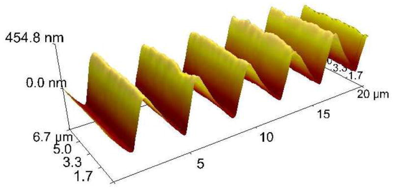
3D AFM topography image of a silk film cast with pattern I. All groove patterns had a similar sawtooth shape, regardless of dimensions.
MSC Alignment on Silk Films
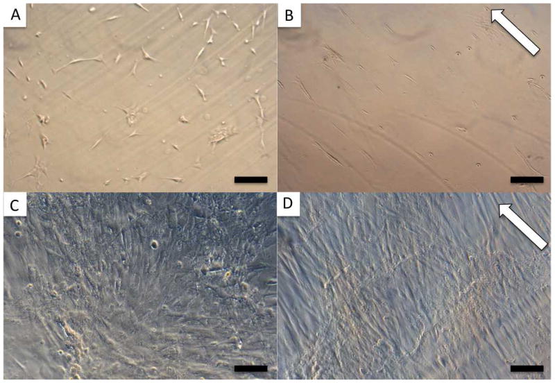
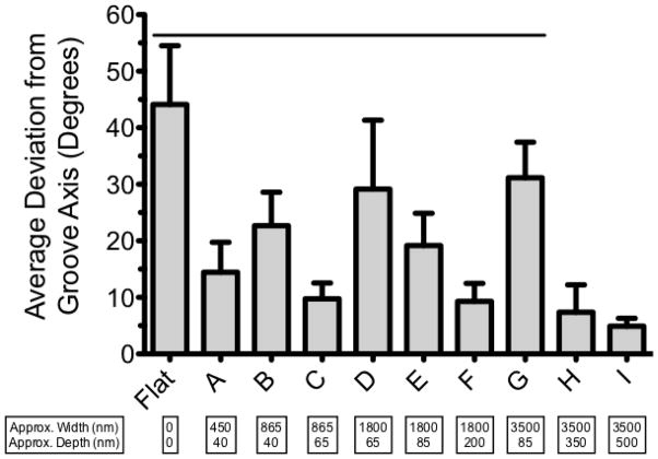
MSC alignment on the 10 different silk film surfaces was assessed after 2 days in culture via phase contrast microscopy. The mean deviation of cell bodies from the substrate groove axis was calculated by averaging the alignment of all the cells contained in at least 3 separate 5x images (Figure 2 A and B). All of the patterned samples produced significantly more alignment than the flat films, with mean deviation angles ranging from 4.9° to 31.2° on the patterned samples compared to 44.1° on the flat films (Figure 3).
Figure 2.
MSCs cultured in proliferation media on FF (A and C) and PF (B and D). 5x images taken 2 days after seeding 104 cells/film (A and B) were used to determine cellular alignment on the different patterns. C and D show 10x images of the confluent cells 16 days after seeding 2 × 10⁴ cells/film. White arrows indicate groove direction, scale bar = 200 μm (A, B), 100 μm (C, D).
Figure 3.
Average deviation angle of MSCs 2 days after seeding on silk films with various groove dimensions. Lower bars represent better alignment. Error bars show SD, line represents significant difference from pattern I (p < 0.05).
In general, the degree of MSC alignment was governed by an interplay between both the width and depth of the groove patterns. Considering patterns of similar depth (A and B; C and D; E and G), it is apparent that the groove width is inversely related to the cell alignment. Alternatively, comparing patterns with similar widths (B and C; D, E, and F; H and I), it is evident that the groove depth directly correlates with the degree of alignment. While both width and depth played a role in how well the cells aligned with the grooves, comparing the 865nm wide patterns (B and C, Figure 3) elucidates the dramatic effect that even a small change in groove depth can have on cell orientation. Increasing the groove depth by approximately 25nm (from ~40nm to ~65nm) improved cellular alignment by nearly 13° (average deviation angle of 22.7° for pattern B and 9.8° for pattern C). Further evidence for the pattern depth playing a more critical role in cellular alignment relative to the pattern width is evidenced by the fact that cells cultured on the deepest, but also widest, grooves (pattern I) had the lowest mean deviation (4.9 ± 1.4°) from the groove axis. These results agree with previous findings for other cell types that groove depth is most critical for inducing cellular alignment 14,15,36.
Pattern I produced significantly better alignment than patterns A – G, orienting MSCs with < 5° average deviation from the groove axis. In addition, pattern I had the most surface roughness (Table 1), a property known to promote osteogenic differentiation 40. As a result, we chose this pattern to compare to flat films in the differentiation experiment.
Osteogenic Differentiation and Gene Expression
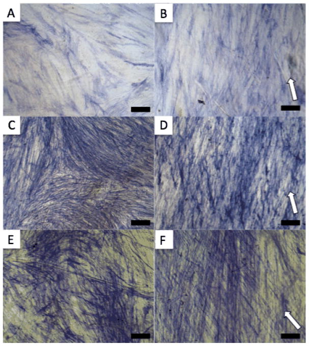
A total of 2 × 10⁴ cells were seeded on either flat silk films (FF) or pattern I films (PF) that were previously sterilized and adhered to the bottom of 24 well plates. The cells were grown to confluence in proliferation media for 16 days (Figure 3 C and D) before switching to osteogenic differentiation media (considered day 0). Cells were fixed and stained for ALP as a marker for osteogenic differentiation at 14, 21, and 28 days (Figure 4). The increasingly dark staining indicates increasing ALP expression over time. The amount of staining was similar between PF and FF at each time point and the orientation effect of the PF on the cells is clearly visible.
Figure 4.
ALP staining of MSCs cultured in osteogenic media on FF (A, C, E) and PF (B, D, F) for 14 (A and B), 21 (C and D) and 28 (E and F) days. White arrows indicate groove direction, scale bar = 100 μm.
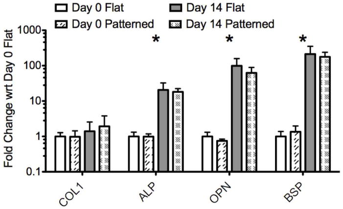
Osteogenic gene expression (ALP, BSP, COL1, and OPN) was quantified at days 0 and 14 through qRT-PCR (Figure 5). Expression levels for each gene of interest are graphed relative to the expression of that gene in the day 0 FF samples. The results of the gene expression analysis clearly show that the MSCs cultured in osteogenic media differentiate towards bone on both PF and FF with similar expression profiles for each gene of interest.
Figure 5.
PCR results. Gene expression is normalized to GAPDH and shown relative to day 0 FF samples on a log scale. Error bars show maximum and minimum values based on the standard deviation of the [delta] [delta] Ct values. Stars indicate a significant difference between day 0 and day 14 (both PF and FF) [delta] Ct values for the gene of interest based on a two-tailed unpaired t-test (p < 0.05).
At day 0, there was no significant difference between PF and FF for any of the genes analyzed (Figure 5), indicating that the PF did not induce spontaneous changes in gene expression during the 16-day proliferation period. At day 14 of differentiation, there was also no significant difference in gene expression levels between the cells cultured on the FF and PF, again indicating that the topographically induced cell alignment on the PF did not affect osteogenesis relative to the FF controls. For both PF and FF samples, COL1 expression increased non-significantly at day 14 relative to day 0, while expression levels of ALP, OPN and BSP were all significantly higher in both groups at day 14 compared to day 0. The roughly two orders of magnitude change in OPN and BSP expression observed on both PF and FF was similar to previous results characterizing MSC differentiation on non-patterned BMP-2 coupled silk films 30. This large change in gene expression is indicative of the MSCs differentiating towards bone from an initially non-osteogenic phenotype. While the PF induced significant morphological changes to the MSCs and their overall organization, they did not affect the expression levels of the genes analyzed during the first 14 days of differentiation. This supports the idea that topographical patterning may be a useful way to achieve cellular organization mimicking in vivo structures without impacting the genetic phenotype of the cells.
Mineralization
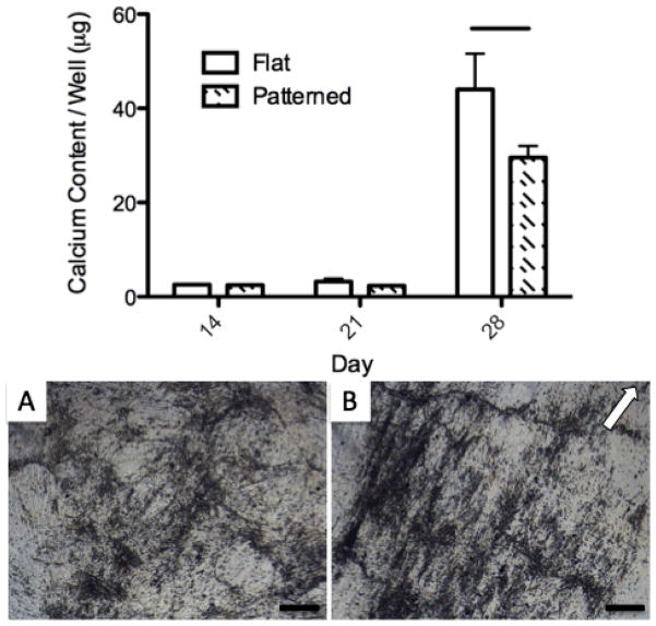
The total calcium content of PF and FF samples was quantified at days 14, 21, and 28 as a marker of mineralized matrix deposition (Figure 6, top). Calcium content was relatively low at days 14 and 21, with no significant difference between the PF and FF. The cells produced a significant amount of mineralization between day 21 and 28, as calcium content was greatly increased on both the PF and FF at the final time point, with significantly more calcium found on the FF.
Figure 6.
Calcium content (top) at 14, 21, and 28 days differentiation and phase contrast images of mineralized ECM formation on FF (A) and PF (B) at day 28. Error bars show SD, line on chart represents significant difference between PF and FF calcium content at day 28. White arrow indicates groove direction. Scale bar = 200 μm.
Mineralized ECM was readily apparent under phase contrast microscopy at day 28 on both FF and PF (Figure 6 A and B). ECM deposition on the PF was closely aligned with the film groove axis, while the deposition on the patterned film was randomly oriented. The mineralized nodules generally followed the groove axis on the PF, with some darker aggregate bands forming perpendicular to the major direction. This alignment of ECM was likely a result of the highly aligned cellular orientation maintained throughout differentiation on the PF (Figure 7 B and F). Despite lower calcium content on the PF compared to the FF at day 28, it is clear that both substrates allow for significant amounts of mineralized ECM deposition by the cells.
Figure 7.
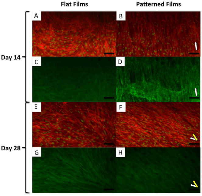
10x fluorescent microscopy images of MSCs differentiated on FF (A, C, E and G) and PF (B, D, F and H) at 14 (A, B, C and D) and 28 (D, E, F and G) days. A, B, E, and F show actin (red) and nuclei (false colored green) staining. C, D, G, and H show staining for collagen type I (green). White arrows indicate groove direction on PF. Yellow arrow indicates secondary alignment of cells in layer distal to substrate. Scale bar = 100 μm.
Cytoskeleton and ECM Orientation
Cells were fixed and stained for actin and collagen at days 14 (Figure 7 A, B, C and D) and 28 (Figure 7 E, F, G and H). Cells on both PF and FF grew into multilayered structures under osteogenic conditions, a prerequisite for the formation of 3D tissues. The cells differentiated on FF maintained a relatively spread morphology and random, non-linear alignment over the 28 days of differentiation. Type I collagen deposition closely followed the cellular orientation on both the FF and PF (Figure 7 C, D, G and H).
At day 14, the cells differentiated on PF had a narrow and elongated morphology and remained well aligned with the groove orientation on the silk substrate (Figure 7 B, white arrow). However, by day 28 of differentiation, an interesting secondary alignment effect was noted on the PF. In some areas of culture, the first layer of cells was covered by a second layer that was also aligned, but at a rotated angle to the groove direction (Figure 7 F, yellow arrow). Type I collagen staining of the multi-layered aligned cells showed deposition primarily oriented with the cell layer distal to the film (Figure 7 H), indicating that these cells were continuing to actively produce ECM after overgrowing the first layer.
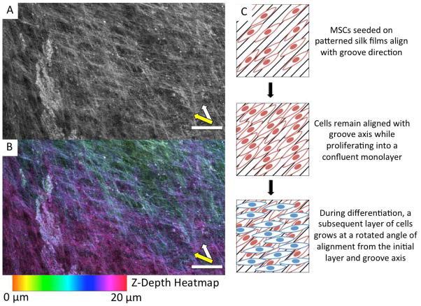
Confocal imaging shows that the two directions of alignment on the PF were associated with multiple layers of cells (Figure 8 A and B). The z-depth heatmap in Figure 8 B illustrates the oblique rotation of the distal layer of cells from the first layer and groove direction. Generally, the second layer of cells were aligned between 30° and 40° from the first layer of cells and the groove axis, as diagrammed in Figure 8 C. This secondary alignment effect can also be seen in the ALP staining of the PF at both day 21 and 28 (Figure 4 D and F). Further evidence of this phenomenon is shown in SEM, phase, and fluorescent images (Supplementary Figures 1 and 2). Interestingly, a similar secondary alignment effect was previously observed, but not emphasized, in a study of MSCs differentiated toward bone on grooved polycarbonate substrates 22.
Figure 8.
Confocal microscope images of a day 28 PF sample stained for actin (A, B). (A) shows a grayscale z-projection of 11 confocal images each spaced 2 μm apart. (B) shows the same z-projection, with each confocal image color-coded based on z-depth. The z-depth scale is relative to the film, where 0 μm is just above the film surface. White arrow indicates the groove direction and orientation of lower cell layer. Yellow arrow indicates secondary alignment of cells in layer distal to substrate. Scale bars = 100 μm. Right, a diagram illustrating the secondary alignment effect observed on some areas of the PF (C).
The rotated alignment of successive layers of cells may be an important finding because it is reminiscent of the rotated and stacked layers of ECM in the twisted plywood model of cortical bone. Giraud-Guille and coworkers have proposed that this structure occurs in native bone as a result of the packing of collagen triple helices 41. Indeed, they have shown that acellular solutions of collagen can spontaneously form cholesteric liquid crystals, a structure characterized by rotated layers of parallel alignment 42. They hypothesize that aligned collagen helices may induce an oblique alignment in the succeeding collagen layer as a result of the second layer orienting along the helical pitch of the first layer. Cholesteric liquid crystals formed from collagen solutions have been documented with twist angles of 22° – 45° depending on concentration 43, which supports the idea that collagen packing drives lamellar bone organization in vivo where twist angles of approximately 30° have been reported 4. In this study, we noted the second layer of cells on PF were aligned approximately 30° – 40° from the groove axis and initial cell orientation. While the packing of collagen helices seems like a plausible explanation for the observed secondary alignment effect, further experiments are necessary to elucidate the true underlying mechanism.
Conclusion
A successful approach to the engineering of functional cortical bone should seek to mimic the structure of the native tissue at the cellular level. Modifying scaffold surface topography is one way to induce the desired cellular organization, which in turn will alter the genetic phenotype of the cells, and in the case of stem cells, the differentiation potential. Our present efforts aimed to characterize the effects of surface patterned silk films on MSC organization and differentiation toward bone in vitro.
Grooved silk films were shown to support soluble-factor induced osteogenic differentiation of MSCs while also producing robust alignment of cells and ECM, a hallmark of native cortical bone. The trends in gene expression and mineralization were similar between the PF and FF groups. While the PF did not appear to enhance the osteogenic potential of MSCs relative to the FF controls, the anisotropic multi-layer lamellar tissue structures that formed on the PF bore more resemblance to the in vivo tissue architecture than the random structures that developed on the FF.
This work can be directly translated to a 3D implantable and degradable scaffold system by stacking of individually seeded films to form multi-lamellar structures, as we have previously demonstrated with corneal cells 35,37. The PF could also be combined with porous salt leached silk sponges to form biphasic scaffolds for the directed formation of both cancellous and cortical tissue engineered bone. The secondary alignment effect observed on the patterned films raises the possibility that simple topopgraphical surface patterns may be useful for inducing more complex, higher order 3D tissue structures. Further investigation into the observed effect could lead to the development of a model system with which to study the formation of rotated lamellar structures in native cortical bone.
Supplementary Material
Acknowledgments
We thank the NIH (P41 Tissue Engineering Resource Center, EB002520) and the AFOSR for funding this work.
Contributor Information
Lee W. Tien, Department of Biomedical Engineering, Tufts University, 4 Colby St. Medford, MA 02155, USA
Eun Seok Gil, Department of Biomedical Engineering, Tufts University, 4 Colby St. Medford, MA 02155, USA.
Sang-Hyug Park, Department of Biomedical Engineering, Jungwon University, 5 Dongbu-ri, Goesan-eup, Goesan-gun, Chungcheongbuk-do, Korea 367-805.
Biman B. Mandal, Department of Biotechnology, Indian Institute of Technology Guwahati 781039, India
David L. Kaplan, Department of Biomedical Engineering, Tufts University, 4 Colby St. Medford, MA 02155, USA.
References
- 1.Butler DL, Goldstein SA, Guilak F. Functional Tissue Engineering: The Role of Biomechanics. J Biomech Eng. 2000;122:570–575. doi: 10.1115/1.1318906. [DOI] [PubMed] [Google Scholar]
- 2.Weiner S, Traub W, Wagner HD. Lamellar bone: structure-function relations. J Struct Biol. 1999;126:241–255. doi: 10.1006/jsbi.1999.4107. [DOI] [PubMed] [Google Scholar]
- 3.Giraud-Guille M. Twisted plywood architecture of collagen fibrils in human compact bone osteons. Calcified Tissue International. 1988;42:167–180. doi: 10.1007/BF02556330. [DOI] [PubMed] [Google Scholar]
- 4.Weiner S, Arad T, Sabanay I, Traub W. Rotated plywood structure of primary lamellar bone in the rat: Orientations of the collagen fibril arrays. Bone. 1997;20:509–514. doi: 10.1016/s8756-3282(97)00053-7. [DOI] [PubMed] [Google Scholar]
- 5.Nerurkar NL, et al. Nanofibrous biologic laminates replicate the form and function of the annulus fibrosus. Nat Mater. 2009;8:986–992. doi: 10.1038/nmat2558. [DOI] [PMC free article] [PubMed] [Google Scholar]
- 6.Grayson WL, Martens TP, Eng GM, Radisic M, Vunjak-Novakovic G. Biomimetic approach to tissue engineering. Seminars in Cell & Developmental Biology. 2009;20:665–673. doi: 10.1016/j.semcdb.2008.12.008. [DOI] [PMC free article] [PubMed] [Google Scholar]
- 7.Weiss P. In vitro experiments on the factors determining the course of the outgrowing nerve fiber. Journal of Experimental Zoology. 1934;68:393–448. [Google Scholar]
- 8.Khademhosseini A, Langer R, Borenstein J, Vacanti JP. Microscale technologies for tissue engineering and biology. Proceedings of the National Academy of Sciences of the United States of America. 2006;103:2480–2487. doi: 10.1073/pnas.0507681102. [DOI] [PMC free article] [PubMed] [Google Scholar]
- 9.Norman JJ, Desai TA. Methods for Fabrication of Nanoscale Topography for Tissue Engineering Scaffolds. Ann Biomed Eng. 2006;34:89–101. doi: 10.1007/s10439-005-9005-4. [DOI] [PubMed] [Google Scholar]
- 10.Martínez E, Engel E, Planell JA, Samitier J. Effects of artificial micro- and nano-structured surfaces on cell behaviour. Annals of Anatomy - Anatomischer Anzeiger. 2009;191:126–135. doi: 10.1016/j.aanat.2008.05.006. [DOI] [PubMed] [Google Scholar]
- 11.Ingber DE. Tensegrity II. How structural networks influence cellular information processing networks. Journal of Cell Science. 2003;116:1397–1408. doi: 10.1242/jcs.00360. [DOI] [PubMed] [Google Scholar]
- 12.Dalby MJ, et al. The control of human mesenchymal cell differentiation using nanoscale symmetry and disorder. Nat Mater. 2007;6:997–1003. doi: 10.1038/nmat2013. [DOI] [PubMed] [Google Scholar]
- 13.Oakley C, Brunette DM. The sequence of alignment of microtubules, focal contacts and actin filaments in fibroblasts spreading on smooth and grooved titanium substrata. J Cell Sci. 1993;106 (Pt 1):343–354. doi: 10.1242/jcs.106.1.343. [DOI] [PubMed] [Google Scholar]
- 14.Clark P, Connolly P, Curtis AS, Dow JA, Wilkinson CD. Topographical control of cell behaviour: II. Multiple grooved substrata. Development. 1990;108:635–644. doi: 10.1242/dev.108.4.635. [DOI] [PubMed] [Google Scholar]
- 15.Andersson AS, Olsson P, Lidberg U, Sutherland D. The effects of continuous and discontinuous groove edges on cell shape and alignment. Experimental Cell Research. 2003;288:177–188. doi: 10.1016/s0014-4827(03)00159-9. [DOI] [PubMed] [Google Scholar]
- 16.Vernon RB, Gooden MD, Lara SL, Wight TN. Microgrooved fibrillar collagen membranes as scaffolds for cell support and alignment. Biomaterials. 2005;26:3131–3140. doi: 10.1016/j.biomaterials.2004.08.011. [DOI] [PubMed] [Google Scholar]
- 17.Biggs MJP, et al. Adhesion formation of primary human osteoblasts and the functional response of mesenchymal stem cells to 330nm deep microgrooves. J R Soc Interface. 2008;5:1231–1242. doi: 10.1098/rsif.2008.0035. [DOI] [PMC free article] [PubMed] [Google Scholar]
- 18.Bruinink A, Wintermantel E. Grooves affect primary bone marrow but not osteoblastic MC3T3-E1 cell cultures. Biomaterials. 2001;22:2465–2473. doi: 10.1016/s0142-9612(00)00434-8. [DOI] [PubMed] [Google Scholar]
- 19.Yim EKF, Darling EM, Kulangara K, Guilak F, Leong KW. Nanotopography-induced changes in focal adhesions, cytoskeletal organization, and mechanical properties of human mesenchymal stem cells. Biomaterials. 2010;31:1299–1306. doi: 10.1016/j.biomaterials.2009.10.037. [DOI] [PMC free article] [PubMed] [Google Scholar]
- 20.Zhu B, Lu Q, Yin J, Hu J, Wang Z. Alignment of osteoblast-like cells and cell-produced collagen matrix induced by nanogrooves. Tissue Eng. 2005;11:825–834. doi: 10.1089/ten.2005.11.825. [DOI] [PubMed] [Google Scholar]
- 21.Matsuzaka K, Walboomers F, Ruijter A, Jansen JA. Effect of microgrooved poly-l-lactic (PLA) surfaces on proliferation, cytoskeletal organization, and mineralized matrix formation of rat bone marrow cells. Clinical Oral Implants Research. 2000;11:325–333. doi: 10.1034/j.1600-0501.2000.011004325.x. [DOI] [PubMed] [Google Scholar]
- 22.Kirmizidis G, Birch MA. Microfabricated Grooved Substrates Influence Cell–Cell Communication and Osteoblast Differentiation In Vitro. Tissue Engineering Part A. 2009;15:1427–1436. doi: 10.1089/ten.tea.2008.0137. [DOI] [PubMed] [Google Scholar]
- 23.Yim EKF, Pang SW, Leong KW. Synthetic nanostructures inducing differentiation of human mesenchymal stem cells into neuronal lineage. Experimental Cell Research. 2007;313:1820–1829. doi: 10.1016/j.yexcr.2007.02.031. [DOI] [PMC free article] [PubMed] [Google Scholar]
- 24.Gray C. Advanced Bone Formation in Grooves in Vitro Is Not Restricted to Calcified Biological Materials. Tissue Engineering. 1998;4:315–323. doi: 10.1089/ten.1998.4.315. [DOI] [PubMed] [Google Scholar]
- 25.Lu X, Leng Y. Comparison of the osteoblast and myoblast behavior on hydroxyapatite microgrooves. Journal of Biomedical Materials Research Part B: Applied Biomaterials. 2009;90B:438–445. doi: 10.1002/jbm.b.31304. [DOI] [PubMed] [Google Scholar]
- 26.Tay CY, et al. Micropatterned matrix directs differentiation of human mesenchymal stem cells towards myocardial lineage. Experimental Cell Research. 2010;316:1159–1168. doi: 10.1016/j.yexcr.2010.02.010. [DOI] [PubMed] [Google Scholar]
- 27.Ber S, Torun Köse G, HasIrcI V. Bone tissue engineering on patterned collagen films: an in vitro study. Biomaterials. 2005;26:1977–1986. doi: 10.1016/j.biomaterials.2004.07.007. [DOI] [PubMed] [Google Scholar]
- 28.Altman GH, et al. Silk-based biomaterials. Biomaterials. 2003;24:401–416. doi: 10.1016/s0142-9612(02)00353-8. [DOI] [PubMed] [Google Scholar]
- 29.Sofia S, McCarthy MB, Gronowicz G, Kaplan DL. Functionalized silk-based biomaterials for bone formation. Journal of Biomedical Materials Research. 2001;54:139–148. doi: 10.1002/1097-4636(200101)54:1<139::aid-jbm17>3.0.co;2-7. [DOI] [PubMed] [Google Scholar]
- 30.Karageorgiou V, et al. Bone morphogenetic protein-23decorated silk fibroin films induce osteogenic differentiation of human bone marrow stromal cells. Journal of Biomedical Materials Research Part A. 2004;71A:528–537. doi: 10.1002/jbm.a.30186. [DOI] [PubMed] [Google Scholar]
- 31.Uebersax L, et al. Effect of Scaffold Design on Bone Morphology In Vitro. Tissue Engineering. 2006;12:3417–3429. doi: 10.1089/ten.2006.12.3417. [DOI] [PubMed] [Google Scholar]
- 32.Rockwood DN, et al. Ingrowth of human mesenchymal stem cells into porous silk particle reinforced silk composite scaffolds: An in vitro study. Acta Biomaterialia. 2011;7:144–151. doi: 10.1016/j.actbio.2010.07.020. [DOI] [PMC free article] [PubMed] [Google Scholar]
- 33.Karageorgiou V, et al. Porous silk fibroin 3-D scaffolds for delivery of bone morphogenetic protein-2 in vitro and in vivo. Journal of Biomedical Materials Research Part A. 2006;78A:324–334. doi: 10.1002/jbm.a.30728. [DOI] [PubMed] [Google Scholar]
- 34.Meinel L, et al. Silk implants for the healing of critical size bone defects. Bone. 2005;37:688–698. doi: 10.1016/j.bone.2005.06.010. [DOI] [PubMed] [Google Scholar]
- 35.Lawrence BD, Marchant JK, Pindrus MA, Omenetto FG, Kaplan DL. Silk film biomaterials for cornea tissue engineering. Biomaterials. 2009;30:1299–1308. doi: 10.1016/j.biomaterials.2008.11.018. [DOI] [PMC free article] [PubMed] [Google Scholar]
- 36.Gil ES, Park SH, Marchant J, Omenetto F, Kaplan DL. Response of Human Corneal Fibroblasts on Silk Film Surface Patterns. Macromol Biosci. 2010;10:664–673. doi: 10.1002/mabi.200900452. [DOI] [PMC free article] [PubMed] [Google Scholar]
- 37.Gil ES, et al. Helicoidal multi-lamellar features of RGD-functionalized silk biomaterials for corneal tissue engineering. Biomaterials. 2010;31:8953–8963. doi: 10.1016/j.biomaterials.2010.08.017. [DOI] [PMC free article] [PubMed] [Google Scholar]
- 38.Lawrence BD, Omenetto F, Chui K, Kaplan DL. Processing methods to control silk fibroin film biomaterial features. J Mater Sci. 2008;43:6967–6985. [Google Scholar]
- 39.Altman GH, et al. Advanced Bioreactor with Controlled Application of Multi-Dimensional Strain For Tissue Engineering. J Biomech Eng. 2002;124:742–749. doi: 10.1115/1.1519280. [DOI] [PubMed] [Google Scholar]
- 40.Boyan BD, et al. Osteoblasts generate an osteogenic microenvironment when grown on surfaces with rough microtopographies. Eur Cell Mater. 2003;6:22–27. doi: 10.22203/ecm.v006a03. [DOI] [PubMed] [Google Scholar]
- 41.Giraud Guille MM, Mosser G, Helary C, Eglin D. Bone matrix like assemblies of collagen: From liquid crystals to gels and biomimetic materials. Micron. 2006;36:602–608. doi: 10.1016/j.micron.2005.07.005. [DOI] [PubMed] [Google Scholar]
- 42.Giraud-Guille MM. Liquid crystallinity in condensed type I collagen solutions : A clue to the packing of collagen in extracellular matrices. Journal of Molecular Biology. 1992;224:861–873. doi: 10.1016/0022-2836(92)90567-4. [DOI] [PubMed] [Google Scholar]
- 43.Mosser G, Anglo A, Helary C, Bouligand Y, Giraud-Guille MM. Dense tissue-like collagen matrices formed in cell-free conditions. Matrix Biology. 2006;25:3–13. doi: 10.1016/j.matbio.2005.09.002. [DOI] [PubMed] [Google Scholar]
Associated Data
This section collects any data citations, data availability statements, or supplementary materials included in this article.


