

Abstract
Traumatic brain injury (TBI) is a major cause of mortality and morbidity. Various attempts have been made to replicate clinical TBI using animal models. The fluid-percussion model (FP) is one of the oldest and most commonly used models of experimentally induced TBI. Both central (CFP) and lateral (LFP) variations of the model have been used. Developed initially for use in larger species, the standard FP device was adapted more than 20 years ago to induce consistent degrees of brain injury in rodents. Recently, we developed a microprocessor-controlled, pneumatically driven instrument, micro-FP (MFP), to address operational concerns associated with the use of the standard FP device in rodents. We have characterized the MFP model with regard to injury severity according to behavioral and histological outcomes. In this protocol, we review the FP models and detail surgical procedures for LFP. The surgery involves tracheal intubation, craniotomy and fixation of Luer fittings, and induction of injury. The surgical procedure can be performed within 45–50 min.
INTRODUCTION
Traumatic brain injury (TBI) is a major cause of death and disability in humans. According to the Centers for Disease Control and Prevention, the annual incidence of TBI in the United States is ~1.7 million1. Motor vehicle accidents are the major cause of fatal head injury, although falls are the leading cause of TBI-related morbidity, particularly among the elderly1. In addition, the use of improvised explosive devices in war zones has resulted in increasing numbers of blast-related head injuries in both military personnel and civilians. Indeed, TBI is considered a ‘signature injury’ of the wars in Iraq and Afghanistan2,3. Concurrently, there has been increased recognition of the frequency and consequences of concussive brain injury associated with athletics4. To better understand the pathobiology of TBI and evaluate potential therapeutic approaches, various animal models have been developed and characterized. Each is intended to mimic certain components of clinical TBI, recognizing that it is difficult to establish consistent models that include most or all of the factors that contribute to post-trauma tissue damage.
Animal models of TBI
Many animal models of experimentally induced TBI have been developed and characterized using different types of mechanical forces. Denny-Brown and Russell5 classified experimental brain injury into two categories: acceleration concussion and percussion concussion. Experimental models of brain injury use mechanical force to cause static or dynamic brain trauma6,7. Static models rely on amplitude and duration of mechanical force to cause trauma-induced morphological and functional impairments6–8. On the other hand, dynamic brain injury can be induced by a defined amplitude, duration, velocity and/or acceleration of a mechanical force6.
Dynamic models of direct brain injury, in which the head motion is either constrained or unconstrained during the infliction of trauma, are further divided into two categories.
-
Impact injury: This type of injury can be induced by the following techniques:
Penetration: Penetrating models use needles or missiles, resulting in crushing and/or laceration of tissue, hemorrhage, and varying degrees of brain distortion and displacement9,10.
Nonpenetration (closed head injury): Various ‘closed’ models of head injury have been developed to reflect events occurring in human concussive or diffuse brain injury6,11. A model developed in rats by Goldman et al.11 used a pendulum to strike the skull midline at a definite angle and force. Graded brain injury can be produced by dropping a weight through a column onto a stainless steel disc cemented centrally on the skull, with injury severity related to the mass of the weight and the height from which the weight is dropped12,13. A variation of this model was developed by Cernak et al.14 using a controlled piston-induced impact onto a midline-positioned plate with the skull intact.
Acceleration: Impact injury has been induced by acceleration with constrained or unconstrained motion of the animal’s head6,15. Marmarou’s weight-drop model is commonly used to induce constrained-impact acceleration head injury in rodents12,13.
Direct brain deformation: Impact through brain deformation is induced in animals by direct delivery of the impact energy to the brain parenchyma after craniotomy, with the dura intact6,15–17. The direct brain deformation models such as FP and rigid indentation (e.g., controlled cortical impact), are commonly used to delineate the mechanisms involved in primary and secondary phases of brain injury6,15. These models cause brain injury through impact energy from fluid pressure or direct mechanical force (piston induced or weight-drop mediated). Such insults result in varying degrees of contusion, shearing and/or stretching of tissue and subdural hematoma, causing rapid ‘primary’ injury to the brain6,15,17–19. This is followed by ‘secondary’ biochemical and physiological changes occurring from seconds to weeks to months after trauma, which lead to further cell loss and tissue damage that result in long-term behavioral deficits6,20,21.
Nonimpact head acceleration injury: Nonimpact head acceleration models have been developed across species, including in pigs and primates, to produce diffuse axonal injury through rotational acceleration by rapid movement of the brain within the skull22,23. The degree of tissue deformation is related to the inertial effect and brain mass22,23.
In recent years, a number of blast models of indirect brain injury in various species have been developed using explosives or compressed air to simulate aspects of human brain injury caused by explosives6,24–26. These models involve subjecting the surface of an animal’s body to a blast wave, with mean peak overpressure in the range of 154–340 kPa, for a particular duration of time6,24–26.
FP model: midline and lateral
The FP model was initially developed for use in sheep, dogs, cats, pigs, and rabbits27–32, and was later adapted for rodents33,34. In the late 1960s at the University of Göteborg, Lindgren and Rinder35–37 developed a mechanical ‘percussion concussion’ brain-injury model in rabbits based on hydraulically induced pressure transients. In mid-1970s at the Medical College of Virginia, Sullivan et al.38 used a similar brain injury model in cats. This model causes graded pathophysiological and morphological changes that can be correlated with the pressure transients induced by a pendulum impacting a fluid-filled chamber connected to the extradural space over the vertex after craniotomy38. Both midline and lateral models were subsequently adapted for use in rats33,34,39. The surgery involves craniotomy to expose the dura and the placement of a female Luer lock that is cemented in place; this is followed by transient compression and/or deformation of the underlying brain using a fluid-mediated pressure pulse6,33,34,39–41. The classical apparatus consists of a cylindrical reservoir filled with sterile isotonic saline (Fig. 1; Amscien instruments, fluid-percussion device with FP 301 signal conditioner, http://amscien.com/AmsFluid.htm). On one end of the reservoir is a transducer connected to a tube with a male Luer lock that attaches to the female Luer lock on the skull. Injury is induced by releasing a pendulum (from a precalibrated angle or height) that strikes a piston at the other end of the device to induce a pressure pulse to the intact dura6,33,34,39–41. As the experimenter is unable to control the exact volume of fluid introduced into the cranium using this device, Stalhammer42 and colleagues developed another modification of Lindgren and Rinder’s model in cats that allows more precise control of the fluid volume. The direction and extent of brain deformation caused by this model is related to the rate and volume of fluid loading, controlled by a volume plunger system, and corresponding pressure transients42.
Figure 1.

Classical model of lateral fluid percussion (LFP; Amscien Instruments). The device consists of five components: the impactor assembly with the pendulum to be released from a precalibrated angle; the cylindrical reservoir filled with sterile, isotonic saline; the signal conditioner for pressure measurement; a pressure transducer with an output to signal conditioner; and the stage for positioning the animal. (This figure is reproduced from the instrument manual (Amscien Instruments, Richmond, Virginia, USA, 2004) with permission).
The midline or central FP (CFP) model involves central (vertex) positioning of the craniotomy site at the midline between bregma and lambda33,34. The lateral model of FP (LFP) positions the craniotomy site over the parietal region, ~4.0 mm lateral to the sagittal suture6,39. Both CFP and LFP models, at moderate severity, cause transient hypertension, elevated intracranial pressure, alteration in cerebral blood flow, increased permeability of the blood-brain barrier, altered ionic homeostasis and neuronal cell death29,33,39,43–45.
Central FP injury is limited to mild and moderate injury, as higher injury severity is associated with brainstem compression and respiratory arrest33,34. Although cognitive and neurological deficits may be observed, they are limited by the substantial mortality rate caused by the severe injuries that produce significant and sustained neurological deficits21,33,34,46,47.
The LFP model produces both focal and diffuse injury with vascular disruption, neuronal cell death and glial proliferation12,39,40,48–51. The lateralization of the injury can be used to investigate and compare the extent of damage in ipsilateral and contralateral hemispheres. In this model, small variations in craniotomy position can cause major differences in severity of tissue damage and associated neurological deficits52. Shifting of the craniotomy site more laterally is associated with less contralateral damage, thus affecting both motor and cognitive outcomes47. LFP causes sustained long-term neurological deficits and greater injury severity than that of the midline model14,40,41,50. From a pathobiological perspective, this model simulates many of the features of human contusive TBI6,40,45,53.
Limitations of the standard FP model
Despite the utility and widespread use of the rodent LFP model, there can be problems with its variability, as the generation of a pressure wave is highly sensitive to certain operational factors. On release, the pendulum impacts the reservoir of saline under the force of gravity. Therefore, accurate leveling of the pendulum is essential for appropriate functioning of the device. However, the weight and length of the cylinder makes appropriate leveling of the LFP device difficult, and its maintenance and calibration is time consuming. In addition, because the device was initially developed for larger species, the size of the reservoir relative to the size of the animal being tested may introduce operational variability. Further, because the pressure-delivery tube typically includes a sharp angle between the horizontal fluid reservoir and the animal’s skull, there is a potentially variable dampening effect. As the Luer lock connections allow air entrapment, the presence of air can markedly affect the pressure curves. Therefore, the reservoir should be tilted periodically to remove any trapped air, after which it must be leveled properly before operation to ensure predictable and reproducible degrees of injury.
Micro-FP device
We developed a ‘Micro-FP’ (MFP) device; this device is a microprocessor-controlled, pneumatically driven device that offers operational advantages over the standard FP model (Fig. 2)54. This device consists of three components: the microprocessor-controlled initiator assembly, the impactor assembly with an air-driven impactor, and a stage for positioning the animal (Fig. 2). Control of the microprocessor is achieved by using a Parallax BASIC Stamp 2sx controller, which is programmed using the parallax-specific basic (PBASIC) programming language and signals through a solid-state relay to the pneumatic pressure valve that generates pressurized air into the pneumatic cylinder (Figs. 2–4). When the control valve is opened, pressurized air supplied from a tank of dry, compressed air enters the pneumatic cylinder, forcing it to extend at a velocity that is directly proportional to the pressure and the flow rate of the compressed air (Fig. 3). A 228.6-mm-long pressure chamber with an internal diameter of 19 mm below the pneumatic cylinder is filled with sterile isotonic saline and bears a piston on top (Fig. 3). When the device is triggered, the pneumatic cylinder extends and impacts the piston, causing the transfer of impact energy to the fluid in the pressure chamber (Figs. 3 and 4). As a result, a transient pressure wave is created within the chamber, and fluid is released from the chamber through a pressure transducer and a 3.18-mm male Luer lock fitting at the bottom of the device. The male Luer fitting is locked on to the female Luer disc, which is cemented over the craniotomy site (Fig. 3).
Figure 2.

MFP device. The device consists of three components: the microprocessor-controlled initiator assembly, the impactor assembly with the air-driven impactor and a stage for positioning of the animal. The injury results from the pressure wave in the form of fluid bolus directly on the exposed dura through the compressed air–driven impactor.
Figure 4.

The initiator assembly of the MFP device. The initiator assembly consists of the fluid percussion pressure regulators and controls for triggering the device, and the Powerlab data acquisition system. The Powerlab system has additional outlets that could be connected to other devices for measurement of temperature and other physiological parameters, such as blood pressure and heart rate. Following injury, the pressure is recorded using the Chart4Windows 4.2 software program.
Figure 3.

The impactor assembly of the MFP device. The impactor assembly consists of three components: the pneumatic cylinder, which relays the pressurized air; the pressure chamber (9 inches long), which is filled with sterile isotonic fluid (saline) and bears a piston on top that transfers the impact energy to the fluid; and a male locking Luer fitting (made from plastic) that ensures tight connection with the female Luer disc (made from steel or plastic) cemented on the skull of the rat.
The impact curve is influenced by the angle of impact (90°) and the distance between the starting position of the pneumatic cylinder and the point of impact. In our device, this distance is set at 50.8 mm. The pressure within the chamber is monitored and recorded by a pressure transducer attached to the bottom head of the chamber. Both pneumatic (delivered) and fluid (received) pressures are recorded using the Powerlab data acquisition system through the Chart4Windows 4.2 software program (see EQUIPMENT section). Any mechanical problem or the presence of air in the chamber can be easily detected by observation of differences between two pressure graphs. The air can be removed through a port at the top of the chamber, which ensures easy drainage and filling of the pressure chamber as required. The pressure chamber, pressure chamber piston, pneumatic control valve, pneumatic cylinder, air and fluid transducers are all mounted onto a modified Sherline miniature 8-direction (xyz) vertical milling table, allowing the operator to align the animal to the pressure output fitting accurately.
Advantages of the MFP device
As the magnitude of injury from the MFP device is dependent on dry compressed air or pneumatic pressure waves, this model offers certain advantages over the original FP device. It is possible to precisely control the impact pressure and dwell time applied to the piston on the pressure chamber. The height of the device can be conveniently adjusted such that the animal is securely positioned. This enables the operator to keep the position of the animal as constant as possible between injuries. Leveling the device is unimportant, as the magnitude of the injury inflicted is unaffected by gravity or operator-specific variability in releasing the initiator assembly of the device. Compared with the classical device, the fact that the MFP is smaller, more compact and vertically oriented makes it easier to remove air in the pressure head.
Standard FP versus the MFP device
In addition to clinical relevance, a suitable experimental model should satisfy several criteria: (i) the ability to produce a response that is quantifiable and consistent across operators; (ii) the ability to show correlation between the extent of damage or outcome measures with the increasing grade of trauma; and (iii) the ability to achieve a controlled range of injury severity by making precise adjustments.
Both FP and MFP devices satisfy each of these criteria. Moderate brain injury induced laterally by FP using either device in rats results with substantial and sustained motor and cognitive deficits, as well as in relatively small interanimal injury variability54–56. In addition, injuries induced by the FP model are sensitive to pharmacological intervention54. The functional and histological outcomes assessed following injuries induced by both FP and MFP devices are comparable (Table 1). The composite neuroscores assessed on postinjury day 14 following injury induced by both devices are remarkably consistent (Table 1). Although the lesion volume measurements across the injuries induced by both models are also very similar, there is greater interanimal injury variability with the standard FP model (Table 1). As indicated above, the MFP device offers the advantages of smaller size and weight, and it is easier to maintain and calibrate. This provides convenience and expediency in resolving operational issues such as releasing air entrapment and ensuring consistency of operational parameters.
TABLE 1.
Comparison between the standard FP and MFP devices.
| Device | Reference no. | Rats per group (n) | Neuroscores (mean ± s.e.m. on day 14) | Lesion volume in mm3 (mean ± s.e.m. on day 21) |
|---|---|---|---|---|
| Standard FP | 54 | 11–12 | 24.5 ± 1.0 | 21.8 ± 3.6 |
| MFP | 52 | 7–8 | 25 ± 1.7 | 20.6 ± 1.5 |
The functional (composite neurological scores) and histological (lesion volume, mm3) outcomes observed in rats on days 14 and 21, respectively, after traumatic brain injury using the classical FP54 and MFP52 devices are highly comparable, but there is less variability in lesion volumes across animals with the MFP device.
Assessment of outcomes following FP injury
In this protocol, we describe a sequential procedure for the induction of lateral brain injury in rats using the FP model. However, all surgical procedures (unless stipulated otherwise) are similar for inducing brain injury using the standard FP and the MFP device, with the various caveats described above. Injury severity is characterized on the basis of mortality rates assessed up to 24 h after trauma. Other parameters such as vital signs, arterial blood gases, intracranial pressure, electrophysiology and return and loss of reflexes can also be assessed41. Long-term motor deficits are determined using a well-characterized composite neurological scoring test21,39,40,54–58. This test is extremely reliable for evaluating TBI-induced motor impairment from hours to 1 year after FP injury39,40,54–61. In addition, other tests of vestibulomotor assessments such as beam balance21,40,62–64, beam walk21,40,62–66 and rotarod21,64 can also be considered. The rotarod test is more sensitive than assays of beam walking and beam balancing21. However, deficits assessed using the rotarod are generally short term, lasting from days to a week21,64. Cognitive outcomes are assessed using acquisition trials of the Morris water maze test21,40,54,56,59–70. The Morris water maze was the first and remains the most commonly used test for assessment of memory deficits following FP-induced brain trauma; these deficits can be observed from 48 h to weeks21,40,54,56,59–67,69,70. Other tests, using an eight-arm radial maze66, a Barnes maze71 and conditioned freezing responses72 can also been considered for determination of post-trauma cognitive impairment. In addition, the novel object recognition test can be modified to be used for cognitive assessment following brain injury73. Injury severity is measured using unbiased stereological lesion volume assessment14,54,55,59,70. Lesion volume can be additionally assessed using high-field magnetic resonance imaging analysis21,54,56,59,70,74. Neuronal cell loss in certain subregions of the hippocampus is also characterized with the FP model14,54.
Experimental design
LFP injury
Lateral FP injury has most often been used for rat TBI studies, although the model can be adapted for mice. Experimental details listed below relate to the rat. The craniotomy site, located between bregma and lambda, can be varied with regard to lateral position depending on the extent of ipsilateral versus contralateral damage required. The generated pressure wave can readily be adjusted to produce injuries of varying severity. For each species or strain and anesthetic used, it is essential to first delineate an injury curve in order to select the injury severity appropriate to the research question. For example, with studies of physiological or pharmacological modulation of injury, it is important to choose injury severities that are neither too mild nor too severe. Mild injuries can result in a ceiling effect, which may provide a false-negative result unless careful attention is paid to power analysis. With severe injuries, particularly after delayed interventions, little modulation may be possible. In our experience with the standard FP device, mild injury occurs at 1.8–2.2 atm, moderate injury occurs at 2.4–2.8 atm and severe injury occurs at pressures > 2.8 atm. With the MFP device, pressures of 2.2–2.4 atm, 2.6–2.8 atm and > 3.0 atm correspond to mild, moderate and severe magnitudes of injury, respectively.
Animals
All animals used should be consistent in terms of strain and sex, given that variability is often observed as a function of strain or sex. Often, male animals have been preferred to eliminate potential variability due to unsynchronized ovulation cycles in females, as well as to reflect the more common sex affected by TBI, unless the objective of the study calls for investigation in female animals. It is important to use animals in a narrow weight range, as weight differences may affect the assessed outcomes. In addition, animals should be obtained from a consistent source, even within the same vendor, to reduce variability. Furthermore, some strains of animals may be less appropriate for certain models of injury or assessment of certain behavioral tests75,76.
Controls
It is important to choose appropriate controls, which may include sham injury (anesthesia plus surgery without FP), naive animals (no anesthesia or surgery) or both. The latter group is important for sensitive biochemical and/or molecular studies, as craniotomy alone may cause mild tissue damage. It is imperative to keep all conditions during surgery as consistent as possible among the groups. To avoid effects of circadian rhythms on the behavior and physiology of animals, all surgeries should be performed at the same time during the day with randomization of the groups.
Anesthetics
We use intraperitoneal (i.p.) administration of 60 mg kg−1 of sodium pentobarbital with a volume of injection of 1 ml kg−1 to induce anesthesia in male Sprague-Dawley rats. The duration of this anesthetic agent in rats is 60–90 min. Female animals require considerably lower pentobarbital doses, which may affect interpretation of treatment studies that include animals of both sexes. The depth of anesthesia is assessed by palpebral and paw-withdrawal reflexes, and the whole surgical procedure must be performed when the animals are completely anesthetized.
Other anesthetic options, such as isoflurane77 and halothane78 inhalation and i.p. injection of ketamine and xylazine79 can also considered. Some laboratories perform Steps 4–18 (see PROCEDURE below) using sodium pentobarbital as the anesthetic, allow the animals to recover for 24 h, and then perform Steps 20–26 the following day under isoflurane or halothane inhalation80,81.
It is critical to choose an appropriate anesthetic agent that shows minimal interaction with the drug treatment under investigation to avoid interference with outcome assessment. In addition, the animals must be handled before injection for 5–10 min to avoid any struggling that can prevent accurate injection and anesthesia.
Other biological parameters of assessment
In addition to mortality rates, various physiological parameters such as mean arterial pressure (MAP), heart rate, respiratory rate, oxygen saturation and core body or brain temperature can be assessed. Noninvasive means of assessment are now increasingly available to monitor such physiological parameters.
MATERIALS
REAGENTS
-
Male Sprague-Dawley rats (300 ± 25 g; Taconic, model no. SD-M)
▲ CRITICAL All procedures involving animals must comply with regulations of the Institutional Animal Care and Use Committee (IACUC) or equivalent oversight organization.
Sodium pentobarbital injection (USP; Ovation Pharmaceuticals, NDC no. 67386-501-55)
Sodium chloride (0.9% (wt/vol), USP; Baxter Scientific, cat. no. NDC0338-0048-04)
Sterile alcohol prep pads (Fisher, cat. no. 06-669-62)
Povidone-iodine (USP prep pads; Professional disposables, cat. no. B71200)
Vetropolycin ophthalmic ointment (Pharmaderm, cat. no. NDC0462-0030-38)
Gill’s hematoxylin stain (Fisher, cat. no. 23-245-653)
Eosin stain (Fisher, cat. no. E514-25)
Phosphate-buffered paraformaldehyde (Fisher, cat. no. SF100-4)
Nontoxic washable white paint (Crayola, cat. no. 54-4100-0-053)
Ethyl alcohol (200 proof, anhydrous; Pharmco-Aaper, cat. no. 111000200)
Xylene (Fisher, cat. no. X5-4)
DPX mount (Sigma, cat. no. 44589)
EQUIPMENT
Standard FP device (Amscien Instruments, model no. FP 302; Dragonfly R&D, model no. HPD-1700) or MFP device with all its major components (not commercially available; additional information on individual parts and assembly of the MFP device can be provided upon request; see Figs. 2–4)
Parallax BASIC Stamp 2sx micro controller (Robot Shop, product no. RB-Plx-08)
Powerlab data acquisition system (AD Instruments, model no. ML870/P)
Chart4Windows 4.2 software program (software version v4.2.4, AD Instruments)
Rodent ventilator (Harvard Apparatus, model no. 683)
Tank of medical compressed air (USP; Airgas Puritan Medical, cat. no. UN1002)
Tank of compressed oxygen, (USP; Airgas Puritan Medical, cat. no. UN1072)
Female Luer fitting (Small Parts, product no. LCN-FC0-10)
Male Luer fitting (Value Plastics, product no. 18MTLL-6)
Stereotaxic frame for rats (Kopf Instruments, model no. 930)
Morris water maze for rats (diameter, 6 feet; Stoelting, model no. 60235)
ANY-maze behavioral tracking software (Stoelting, cat. no. 60000)
Video camera (Imaging Source, order no. DMK21AUC03)
Cryostat (Leica, model no. CM3050S)
Stereologer 2000 program (SRC)
Cyanoacrylate adhesive or Vetbond (Revival Animal Health, item no. 27122-435)
Dental cement kit (Stoelting, cat. no. 51458)
Micro drill (Fine Science Tools, item no. 18000-17)
Micro drill trephine (5 mm in diameter; Fine Science Tools, item no. 18004-50)
Surgical instruments (Stoelting): scalpel handle (cat. no. 52174), scalpel blade (cat. no. 52175-20), forceps (cat. nos 52100-40 and 52100-52), scissors (cat. nos 52138-02 and 52132-10) and dissecting retractor (cat. no. 52126-10)
Temperature measurement with rectal probe (Physitemp, model no. BAT-12)
Wound closing 9 mm EZ clips (Stoelting, cat. no. 59022)
Ethibond polyester surgical suture (Ethicon, cat. no. B-926)
Electric heating pad (UL, model no. UL130)
Oster finisher shaver (UL, model no. 53-03H)
Nitrile exam gloves (Fisher, cat. no. 19-130-1597)
Surgical gown (Fisher, cat. no. 19-065-278)
Glass histology slides (Fisher, cat. no. 22-046-500)
Coverslips (Fisher, cat. no. NC9661908)
PROCEDURE
Preparation of FP device ● TIMING ~5 min
▲ CRITICAL STEP If relevant to the experiment being performed, motor responses of all rats should be assessed 1 d before injury using the composite neurological scoring method outlined in Box 1.
BOX 1. ASSESSMENT OF MOTOR RESPONSES USING COMPOSITE NEUROLOGICAL SCORING ● TIMING ~10–15 MIN PER RAT PER DAY (ON POSTSURGERY DAYS 1, 3, 7, 14 AND 21).
▲ CRITICAL STEP The scoring must be performed by an observer blinded to the groups to prevent any unintended bias. All rats must be subjected to the motor tests 1 d before surgery to obtain their neuromotor scores before induction of injury.
Composite neurological scores are usually obtained on postsurgery days 1, 7, 14 and 21. The composite neuroscore reflects a combination of certain individually scored tests14,39,40,54–59. Each test is scored using an ordinal scale ranging from 0 (severe impairment) to 5 (normal function), and total composite functional neurological score (from 0 to 35) is obtained by combining the scores of the following tests:
Lateral pulsion: This assesses the degree of resistance to a lateral push (left and right)14,39,40,54–59.
Forelimb flexion: This evaluates the reflex extension of the forelimb to break a fall when suspended by the tail (left and right)14,39,40,54–59.
-
Inclined plane: This measures the ability to maintain position on an inclined plane (angle board) in two vertical and two horizontal positions and the maximum angle at which the animal can stand for 5 s ( > 50° = 5, 45–50° = 4, 40–45° = 3, 35–40° = 2, 30–35° = 1 and < 29° = 0)14,39,40,54–59.
▲ CRITICAL STEP The type of the material used on the board determines the angle range, which varies from laboratory to laboratory. We use a wooden inclined-angle board.
Statistics: The statistical differences between groups with respect to the ordinal measurements (neurological motor outcomes) are analyzed and determined at designated time points using nonparametric repeated measures; the statistical methods used are the Kruskal-Wallis analysis of variance (ANOVA) followed by individual Mann-Whitney U-tests. The number of animals per group should reflect a power analysis.
-
1|
Inspect the FP device to ensure that there is no air in the pressure chamber filled with saline; this can affect the pressure of the injury.
▲ CRITICAL STEP The calibration of the injury device before surgery initiation is critical to ensure its smooth and accurate operation. This can be performed by triggering the device several times to simulate increasing degrees of injury and reading corresponding pressure values.
? TROUBLESHOOTING
-
2|
Turn on the FP device and open Powerlab and Chart4Windows 4.2 software programs
▲ CRITICAL STEP The force of impact is controlled through a computer connected to the FP device and the Powerlab system, and recorded through the Chart4Windows 4.2 software program. Malfunctioning of these devices and programs can interfere with the impact and/or recording of the pressure of the impact.
Surgical preparation and tracheal intubation ● TIMING ~10 min
-
3|
Weigh the rat to determine the amount of anesthetic required and anesthetize it with the appropriate dose.
! CAUTION All anesthesia and surgery procedures must comply with guidelines of the IACUC or an equivalent organization. Wear a surgical gown and gloves before handling the animal and keep the surgical area aseptic. Sterilize all surgical instruments by autoclaving before surgery. During surgery, instruments can be sterilized as necessary using a hot-bead sterilizer to prevent contamination.
-
4|
Assess the depth of the anesthesia by monitoring the rat’s respiration rate, as well as its palpebral and paw-withdrawal reflexes.
-
5|
Shave the animal’s head over the potential surgical site.
-
6|
Place the animal in a supine position for tracheal intubation. Turn on the ventilator and ensure that it is appropriately connected to the tank supplying compressed oxygen.
-
7|
Insert a laryngoscope into the mouth of the rat to reveal the epiglottis. Carefully slide a 14-gauge intravenous catheter into the trachea with a guide wire.
▲ CRITICAL STEP Care must be taken to prevent the catheter from entering the esophagus. If there is any resistance experienced while inserting the catheter, it should be removed and re-inserted to avoid injury.
-
8|
Remove the laryngoscope and the guide wire from the catheter once it has been successfully inserted into the trachea.
-
9|
Connect the catheter to the ventilator tube and fix its position by suturing around the mouth of the animal using nonabsorbable sterile surgical suture.
▲ CRITICAL STEP Once the ventilator is connected to the catheter, it is crucial to monitor the inspiration and expiration to ensure correct positioning of the catheter.
-
10|
Place the rat on a heated pad, monitor the core body temperature using a rectal probe thermometer and maintain the temperature at 38 ± 0.2 °C.
Craniotomy and fixation of the female Luer lock disc ● TIMING ~30 min
-
11|
Position the rat’s head on a stereotaxic frame and apply ophthalmic ointment to the eyes to prevent them from drying. Disinfect the surgical site on the scalp using povidoneiodine followed by alcohol.
-
12|
Make a 10-mm longitudinal midline incision with a scalpel to expose the skull.
▲ CRITICAL STEP The skin and fascia should be retracted such that the skull is completely exposed; this is critical for identifying the sagittal and coronal sutures on the skull.
-
13|
Open the incised tissue over the skull using a microdissecting retractor so that the midline and bregma and lambda sutures are clearly visible on the skull.
-
14|
Measure and mark a position between bregma and lambda, 4 mm lateral to the midline over the left parietal cortex, using calipers. This marks the position of craniotomy.
▲ CRITICAL STEP Removal of any tissue around the marked position is crucial to prevent it from interfering with the drill while performing the craniotomy.
▲ CRITICAL STEP If necessary, the bone over the craniotomy site can be drilled down to make the surface smooth.
-
15|
Perform a 5-mm craniotomy over the marked position, applying minimal pressure against the skull using a micro drill with a 5-mm-diameter trephine.
▲ CRITICAL STEP While performing the craniotomy, it is crucial to avoid injury to the brain from drilling, and the dura must remain intact. Accordingly, drilling must be performed slowly while carefully checking the skull.
▲ CRITICAL STEP Saline should be applied to the craniotomy site during surgery to prevent tissues from drying and to reduce drilling friction.
-
16|
Attach a metal or plastic female Luer lock disc to the craniotomy site using cyanoacrylate adhesive followed by dental cement. Wait for 15 min for the disc to be firmly fixed over the site while monitoring the rat’s respiration and the depth of anesthesia.
▲ CRITICAL STEP The cement should be applied around the disc rapidly to prevent it from drying during application. It must be completely dry before the procedure can be continued. Inadequate attachment of the disc to the exposed site can lead to leakage of saline during injury and interfere with impact pressure.
▲ CRITICAL STEP To prevent interference with the fluid pulse, the cyanoacrylate adhesive and cement must not be allowed to come in contact with the dura.
-
17|
Once the disc is fixed, fill it gently with saline using a syringe.
-
18|
If surgery is being performed on an animal in the sham control group (rats subjected to craniotomy but no injury), proceed directly to Step 25. Otherwise continue to Step 19 to induce trauma.
Induction of trauma ● TIMING ~5 min
-
19|
Inspect the device again before inflicting injury to ensure the absence of air in the chamber. Check the operation of the device several times by tightly closing the other end of the male locking Luer fitting using a syringe or finger and triggering the device; read corresponding pressure values using the software programs described above.
? TROUBLESHOOTING
-
20|
Attach the female Luer lock disc to the male Luer fitting on the FP device. Use the locking mechanism of the male Luer fitting to ensure a reliable and tight connection with the female disc. Position the rat under the FP device such that the affixed disc is in the same plane as the end of the device connected to it.
▲ CRITICAL STEP Inappropriate attachment to the device can lead to leakage during the impact and interfere with the pressure of injury. It is crucial to screw the lock on the male Luer fitting once the female disc is attached.
-
21|
Hold the head of the rat firmly and subject it to an injury of the desired pressure (usually a moderate degree of severity corresponding to 2.2–2.8 atms or 2.6–2.8 atms for the standard FP or MFP device, respectively) by arming the device and pressing the trigger. Using the software, record the exact pressure of injury induced.
-
22|
Remove the rat from the device and gently remove the Luer lock fitting.
Postoperative care ● TIMING ~1–3 h
-
23|
Observe any swelling and bleeding at the site of injury and clean the injured area.
-
24|
Close the scalp using metallic wound closure clips or surgical sutures.
-
25|
Allow the animal to recover on a heated pad for 3 h after injury.
▲ CRITICAL STEP It is strongly recommended to maintain the animal on the respirator after anesthesia and through the injury to prevent apnea or hypoxia, particularly in more severe injury, until regular respiration is restored.
-
26|
Transfer the animals to a housing facility with a 12-h light-dark cycle and free access to food and water until postinjury assessments can be carried out.
Postinjury behavioral assessment
-
27|
To test postinjury motor responses, follow the instructions in Box 1. To evaluate postinjury cognitive functions, follow the instructions in Box 2. Histology and stereology can be assessed as described in Steps 28–32.
BOX 2. EVALUATION OF COGNITIVE OUTCOMES.
Cognitive outcomes should be assessed using the Morris water maze on postsurgery days 14–18. However, later time points may also be used as required by the research question. This test measures spatial learning based on ability of the animal, using distinct extramaze cues, to locate a hidden platform in a circular pool of water14,21,40,54,59–70. The pool is divided into four quadrants and the location of the platform is kept constant within one of the quadrants throughout the test. The surface of the water is made opaque by mixing the water with white, nontoxic paint. Various modified versions of Morris water maze have been developed and characterized to evaluate cognitive function after brain injury. All the parameters and tracks are recorded by an overhead video camera connected to a computer with ANY-maze behavioral tracking software. The water maze is performed in three phases:
(i) Acquisition on postsurgery days 14–17: This involves subjecting the animal to four trials of acquisition on each day of assessment such that every trial differs in terms of the point of introduction into the maze. The duration of each trial is 90 s and the intertrial interval is 20–30 min. The parameters assessed are latency to find the platform, mean swimming velocity and total distance traveled. The ANY-maze software for tracking and assessment of data is programmed so that the trial ends 10 s after the animal finds the platform. However, every time the animal is unable to locate the platform (four trials per day) at the end of the trial it is placed again on the platform for 25 s on day 14 or 15 s on other days of the acquisition phase. ● TIMING ~2h for 8 rats on each day of assessment
(ii) Probe test on postsurgery day 18: This involves removal of the platform from the maze and subjecting the animal to one trial of 60 s. The time the rat spends in the quadrant in which the platform was earlier submerged is evaluated. ● TIMING ~1 min per rat
(iii) Visual probe or cue test on postsurgery day 18: This involves placing the platform into its original location in the maze and putting a distinct flag on it. The animal is subjected to one trial of 90 s and the latency to locate the flagged platform is assessed. This phase evaluates the visual acuity and swimming ability of the animal. ● TIMING ~90 s per rat
Statistics: The statistical differences between groups with respect to all assessed data (± s.e.m.) from postsurgery days 14–17 are analyzed and evaluated using repeated-measures ANOVA followed by individual appropriate post hoc tests at each time point. The parameters obtained from the probe trial and cue test are statistically analyzed using one-way ANOVA followed by appropriate post hoc tests to determine significant differences between groups.
Histology and stereology ● TIMING ~4 h 30 min (plus 24–48 h of storage time)
-
28|
After administering anesthesia using 65 mg Kg−1 (i.p.) of sodium pentobarbital, perfuse rats transcardially with isotonic saline, followed by 4% (vol/vol) paraformaldehyde.
▲ CRITICAL STEP Animals can be killed at various time points after injury to assess the lesion volume of the brain sections. Cell counts can also be performed on the sections for determining injury-induced neuronal cell loss. Following motor and cognitive assessments, described in Boxes 1 and 2, animals can be killed on postsurgery day 21. More extended follow-up time periods can be used if desired with more delayed cognitive assessment and repeated weekly combined neuroscore assessment.
-
29|
After perfusion, store the brains in 20% (wt/vol) sucrose overnight and then in 30% (wt/vol) sucrose for 24–48 h.
-
30|
Prepare coronal brain sections of 20 μm thickness using a cryostat and mount the sections on previously numbered glass slides.
-
31|
Rehydrate the slices in decreasing concentrations of ethanol (Absolute, 95%, 70% and 50% (vol/vol)). After rehydration, stain the slices with Gill’s hematoxylin, counterstain them in 2.5% (wt/vol) eosin, dehydrate them and cover them with coverslips.
-
32|
Use the Stereologer 2000 program (stereology software) to assess lesion area, including both the cavity and surrounding damaged tissue14,54,59,70 (as described in option A), or to count cells in specific regions54, such as subregions of the hippocampus, the dentate gyrus and the cornu ammonis 3 (CA3) (option B).
▲ CRITICAL STEP Because of the nonuniform nature of damage induced by FP injury, lesion volume and cell loss should be assessed in multiple sections taken at set intervals along the rostrocaudal extent of the damaged area.
(A) Measuring lesion volume
Outline the cavity and surrounding damaged area.
Use the Stereologer program (based on unbiased stereology) to assess the lesion volume by the Cavalieri method. The program calculates the individual subvolumes within one section by multiplying the cross-sectional area with the distance between sections. The final lesion volume is obtained by summation of individual subvolumes. The mean values with standard errors (± s.e.m.) of individual lesion volumes are considered for statistical analysis.
Evaluate the statistical differences between groups in terms of lesion volumes (in mm3) using Student’s t-test. Usually, three slides, with four sections mounted on each slide, are selected such that 12 sections are analyzed from each brain. The same number of slides should be selected from each group.
(B) Cell counting in specific regions
Outline the area around subregions of interest using a ×1.5 objective.
Count the cells within the area using a ×100 objective.
Use the Stereologer 2000 program to estimate the cell numbers by using the fractionator sampling method.
Statistically evaluate the measures of cell numbers between groups by running a one-way analysis of variance (ANOVA) test followed by appropriate post hoc analysis. Usually, three slides, with four sections mounted on each slide, are selected such that 12 sections are analyzed from each brain. The same number of slides should be selected from each group.
● TIMING
Steps 1 and 2, Preparation of FP device: ~5 min
Steps 3–10, Surgical preparation and tracheal intubation: ~10 min
Steps 11–18, Craniotomy and fixation of female Luer lock disc: ~30 min
Steps 19–22, Induction of trauma: ~5 min Steps 23–26, Postoperative care: ~1–3 h
Step 27, Postinjury behavioral assessment: see timing for Boxes 1 and 2 (below)
Box 1, Composite neuroscore assessment: 10–15 min per rat per day of assessment (on postsurgery days 1, 3, 7, 14 and 21)
Box 2 (i): ~2h for 8 rats on each day of assessment (on postsurgery days 14, 15, 16 and 17)
Box 2 (ii): ~1 min per rat (on postsurgery day 18)
Box 2 (iii): ~90 s per rat (on postsurgery day 18)
Steps 28–32, Histology and stereology: ~4 h 30 min (plus 24–48 h to store brains in sucrose)
? TROUBLESHOOTING
Troubleshooting advice is provided in Table 2.
TABLE 2.
Troubleshooting table.
| Device | Step | Problem | Possible reason | Solution |
|---|---|---|---|---|
| Standard FP device | 1,19 | Inconsistency between pressure curves and injury severity | Presence of air in reservoir | Level the cylindrical reservoir and open a valve centered on the top of the reservoir to remove trapped air Introduce saline from the side that is connected to the transducer tube to remove trapped air Check the operation of the device to ensure removal of air |
| MFP device | 1,19 | Inconsistency between pressure curves and injury severity | Presence of air in pressure chamber | Using the locking swivel attached to the base of pressure chamber, tilt the chamber after opening the valves on top and bottom Introduce saline from the bottom of the chamber, removing air through the valve on the top Close the valve immediately Check operation of the device several times to ensure the removal of air from the system |
Air entrapment in the cylindrical reservoir (standard FP device) or the pressure chamber (MFP device) can result in inconsistency between pressure curves and degrees of injury severity. The trapped air must be removed to ensure reliability and reproducibility of injury across animals.
ANTICIPATED RESULTS
Various biological indicators such as vital signs, arterial blood gases, loss and return of reflexes and mortality rates have been found to be useful tools for measuring different degrees of injury severity induced by LFP39,40,82 FP-induced brain injury results in systemic hypertension and bradycardia at different magnitudes of injury39. Moderately injured animals experience initial elevation in MAP, which normalizes within 5 min (ref. 39). Animals subjected to severe injury show increased MAP followed by reduced MAP39. Increasing grades of injury severity are associated with progressively higher mortality rates in a nonlinear fashion, which largely reflects cardiorespiratory suppression39,40,82–84.
To delineate an injury curve for the LFP model using the MFP device on the basis of mortality rates, rats (n = 6–8 per group) were subjected to varying degrees of injury severity (2.4–3.2 atms). All protocols involving the use of animals complied with appropriate animal care guidelines and regulations and were approved by the IACUC at Georgetown University Medical Center. Mortality rates were 0% at 2.4 atms, 12% at 2.6 atms, 20% at 2.8 atms, 33% at 3.0 atms and > 65% above 3.2 atms (Fig. 5). The significant mortality rates at higher degrees of injury is the reason why moderate degrees of severity have been most widely studied. Death from more severe injury usually occurs within the first hour after trauma.
Figure 5.
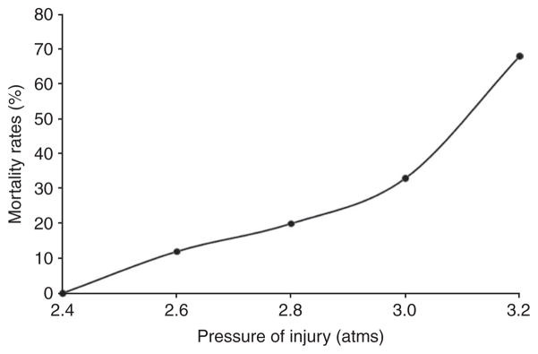
Mortality rates (%) associated with different pressures (atm) of injury. The mortality rates in rats were assessed up to 24 h following impacts ranging from 2.4 to 3.2 atm. Mortality was observed, especially at higher degrees of trauma and usually within 30–60 min.
In addition, the LFP model was characterized on the basis of behavioral outcomes using composite neuromotor scoring and Morris water maze testing. Animals were divided into three groups (n = 6–8 rats per group): sham, mildly injured and moderately injured. The animals subjected to mild and moderate injuries showed significantly lower composite neuroscores compared with sham controls (Fig. 6). There was a statistically significant difference in composite neuroscore among groups with sham, mild and moderate injuries (Kruskal-Wallis analysis, 8.375; P < 0.02, Fig. 6). The individual Mann-Whitney U-tests for multiple comparisons revealed injury-induced significant impairments in motor function compared with the sham group at all time points of assessment (a,bP < 0.005 and eP < 0.001; Fig. 6). In addition, there was a statistically significant difference between mildly and moderately injured animals on postsurgery days 7, 14 and 21 (cP < 0.02 and dP < 0.01; Fig. 6). Evaluation of cognitive deficits in moderately injured rats using the Morris water maze revealed significant memory impairment in terms of latency in locating the platform (Fig. 7). The continuous variables (values of latency in locating the platform) were analyzed using repeated-measure ANOVA followed by one-way ANOVA at each time point. The time to find the platform was significantly longer for the moderately injured group on postsurgery days 16 and 17 when compared with rats subjected to mild injury (aP < 0.01; Fig. 7) and sham injury (bP < 0.001; Fig. 7). However, there was no statistically significant difference in terms of latency to locate the platform between sham and mildly injured groups at any time point of assessment. Thus, the MFP model was able to induce different degrees of injury in a reliable manner and caused an injury severity-dependent loss of function. Histological assessment using unbiased stereology revealed that there was also a significant difference in lesion volumes between mildly and moderately injured groups (t = − 5.967, P < 0.001; Fig. 8). One-way ANOVA followed by post hoc comparisons using Tukey’s test indicated that both mild and moderate injuries caused significant (P < 0.001; Fig. 9) loss of cells in the CA3 sub-region of hippocampus when compared with the sham group. In addition, a significant difference in CA3 cell loss between groups with mild and moderate injuries was determined by one-way ANOVA followed by post hoc comparisons using Bonferroni’s test (P < 0.05; Fig. 9).
Figure 6.

Assessment of composite neurological scores. The composite neuroscores (± s.e.m.) of rats with sham, mild and moderate injuries were assessed using measures of lateral pulsion, forelimb flexion and inclined plane in two vertical and two horizontal positions 1 d before surgery and postsurgery days (DAI: day after injury) 1, 7, 14 and 21. Both mild and moderate injuries induced significant motor impairments compared with sham injuries or either other degree of injury at various postinjury time points of assessment: aP < 0.005 mild versus sham; bP < 0.005 moderate versus sham; cP < 0.02 mild versus moderate; dP < 0.01 mild versus moderate and eP < 0.001 sham versus mild.
Figure 7.

Assessment of cognitive performance. The cognitive outcomes of sham, mildly and moderately injured rats were assessed using the acquisition trials of the Morris water maze test from postsurgery days 14–17 (trial days 1–4 of acquisition phase). The cognitive performance in terms of latency to locate the platform or the total duration of the trial (in seconds; ± s.e.m.) was significantly impaired by moderate injury when compared to groups with mild injury (aP < 0.01) and sham (bP < 0.001) injury.
Figure 8.
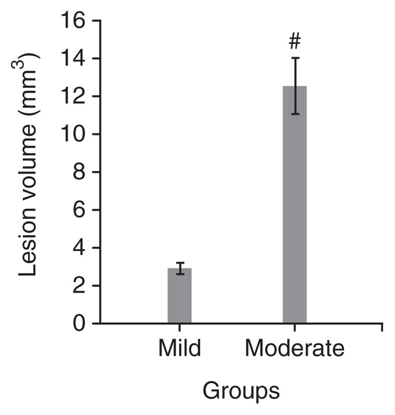
Assessment of lesion volumes by histology. The lesion volumes (in mm3; ± s.e.m.) of the brain sections of animals were determined following cavitation on postsurgery day 21. There was significant difference in injury volume observed between groups with mild and moderately injuries (t = − 5.967; P < 0.001, #: statistically significant difference versus mild injury).
Figure 9.
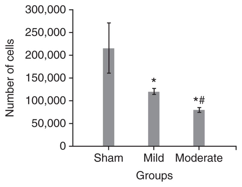
Determination of neuronal cell loss in CA3 subregion of the hippocampus. Trauma-induced, severity-dependent neuronal cell loss (± s.e.m.) was observed in the CA3 subregion of the hippocampus at day 21 after injury. Both mild and moderate injuries caused an injury severity–dependent loss of cells in CA3 region (P < 0.001, *: statistically significant difference versus sham; P < 0.05, #: statistically significant difference versus mild injury).
In conclusion, FP-induced brain injury causes severity-dependent behavioral (neuromotor and cognition) and histological (lesion volume and CA3 cell number) changes, and can readily be used both to study pathobiological mechanisms and/or potential treatment strategies39,54–67,69. The neurological impairment and histological damage induced by the MFP54 device are comparable to those produced by the classical FP instrument (Table 1)39,55–59, but the MFP device may have certain advantages with regard to calibration, troubleshooting and consistency. The FP model of brain injury, although developed initially for use in larger species27–32,35–38, has proved both useful and reliable for evaluation of rodents33,34,39–41,43–67,69,72,78.
Acknowledgments
This study was supported by the National Institutes of Health Grant no. NS052568. We would like to thank D.J. Loane for his helpful comments on the paper.
Footnotes
COMPETING FINANCIAL INTERESTS The authors declare no competing financial interests.
Reprints and permissions information is available online at http://npg.nature.com/reprintsandpermissions/.
AUTHOR CONTRIBUTIONS The project was conceived by A.I.F and was supported by the National Institutes of Health Grant no. NS052568 to A.I.F. The study was designed by A.I.F., B.A.S. and G.D.H. D.N.Z. originally developed the model. G.D.H. and S.V.K. equally contributed to the paper in terms of conducting the study, compiling the results and writing the paper.
References
- 1.Centers for Disease Control and Prevention. Get the Stats on Traumatic Brain Injury in the United States. Centers for Disease Control and Prevention; Atlanta, Georgia, USA: 2010. < http://www.cdc.gov/traumaticbraininjury/pdf/BlueBook_factsheet-a.pdf>. [Google Scholar]
- 2.French LM, Parkinson GW. Assessing and treating veterans with traumatic brain injury. J Clin Psychol. 2008;64:1004–1013. doi: 10.1002/jclp.20514. [DOI] [PubMed] [Google Scholar]
- 3.Hoge CW. Mild traumatic brain injury in U.S. soldiers returning from Iraq. N Engl J Med. 2008;358:453–463. doi: 10.1056/NEJMoa072972. [DOI] [PubMed] [Google Scholar]
- 4.Ellemberg D, Henry LC, Macciocchi SN, Guskiewicz KM, Broglio SP. Advances in sport concussion assessment: from behavioral to brain imaging measures. J Neurotrauma. 2009;26:2365–2382. doi: 10.1089/neu.2009.0906. [DOI] [PubMed] [Google Scholar]
- 5.Denny-Brown D, Russell WR. Experimental cerebral concussion. Brain. 1941;64:93–164. doi: 10.1113/jphysiol.1940.sp003887. [DOI] [PMC free article] [PubMed] [Google Scholar]
- 6.Cernak I. Animal models of head trauma. Neuro Rx. 2005;2:410–422. doi: 10.1602/neurorx.2.3.410. [DOI] [PMC free article] [PubMed] [Google Scholar]
- 7.David S, Aguayo AJ. Axonal regeneration after crush injury of rat central nervous system fibres innervating peripheral nerve grafts. J Neurocytol. 1985;14:1–12. doi: 10.1007/BF01150259. [DOI] [PubMed] [Google Scholar]
- 8.Park HJ, et al. Redistribution of facial nerve motor neurons after recovery from nerve crushing injury in the gerbil. Acta Otolaryngol. 1995;115:273–275. doi: 10.3109/00016489509139307. [DOI] [PubMed] [Google Scholar]
- 9.Finnie JW. Pathology of experimental traumatic craniocerebral missile injury. J Comp Pathol. 1993;108:93–101. doi: 10.1016/s0021-9975(08)80231-9. [DOI] [PubMed] [Google Scholar]
- 10.Carey ME. Experimental missile wounding of the brain. Neurosurg Clin N Am. 1995;6:629–642. [PubMed] [Google Scholar]
- 11.Goldman H, et al. Cerebrovascular changes in a rat model of moderate closed-head injury. J Neurotrauma. 1991;8:129–144. doi: 10.1089/neu.1991.8.129. [DOI] [PubMed] [Google Scholar]
- 12.Marmarou A, et al. A new model of diffuse brain injury in rats. Part I: pathophysiology and biomechanics. J Neurosurg. 1994;80:291–330. doi: 10.3171/jns.1994.80.2.0291. [DOI] [PubMed] [Google Scholar]
- 13.Foda MA, Marmarou A. A new model of diffuse brain injury in rats. Part II: morphological characterization. J Neurosurg. 1994;80:301–313. doi: 10.3171/jns.1994.80.2.0301. [DOI] [PubMed] [Google Scholar]
- 14.Cernak I, et al. The pathobiology of moderate diffuse traumatic brain injury as identified using a new experimental model of injury in rats. Neurobiol Dis. 2004;17:29–43. doi: 10.1016/j.nbd.2004.05.011. [DOI] [PubMed] [Google Scholar]
- 15.Finnie JW, Blumbergs PC. Traumatic brain injury. Vet Pathol. 2002;39:679–689. doi: 10.1354/vp.39-6-679. [DOI] [PubMed] [Google Scholar]
- 16.Blumbergs PC, et al. Diffuse axonal injury in head trauma. J Neurol Neurosurg Psychiatry. 1989;52:838–841. doi: 10.1136/jnnp.52.7.838. [DOI] [PMC free article] [PubMed] [Google Scholar]
- 17.Finnie JW, et al. Traumatic axonal injury in lambs: a model for paediatric axonal damage. J Clin Neurosci. 1999;6:38–42. doi: 10.1016/s0967-5868(99)90601-x. [DOI] [PubMed] [Google Scholar]
- 18.Betz AL, et al. Brain edema: a classification based on blood–brain barrier integrity. Cerebrovasc Brain Metab Rev. 1989;1:133–154. [PubMed] [Google Scholar]
- 19.Smith DH, et al. Progressive atrophy and neuron death for one year following brain trauma in the rat. J Neurotrauma. 1997;14:715–727. doi: 10.1089/neu.1997.14.715. [DOI] [PubMed] [Google Scholar]
- 20.DeKosky ST, et al. Secondary injury after head trauma: subacute and long-term mechanisms. Semin Clin Neuropsychiatry. 1998;3:176–185. [PubMed] [Google Scholar]
- 21.Hamm RJ. Neurobehavioral assessment of outcome following traumatic brain injury in rats: an evaluation of selected measures. J Neurotrauma. 2001;18:1207–1216. doi: 10.1089/089771501317095241. [DOI] [PubMed] [Google Scholar]
- 22.Meythaler JM, et al. Current concepts: diffuse axonal injury-associated traumatic brain injury. Arch Phys Med Rehabil. 2001;82:1461–1471. doi: 10.1053/apmr.2001.25137. [DOI] [PubMed] [Google Scholar]
- 23.Marguiles SS, Thibault LE. An analytical model of traumatic diffuse brain injury. J Biomech Eng. 1989;111:241–249. doi: 10.1115/1.3168373. [DOI] [PubMed] [Google Scholar]
- 24.Cernak I, et al. Blast injury from explosives munitions. J Trauma. 1999;47:96–103. doi: 10.1097/00005373-199907000-00021. [DOI] [PubMed] [Google Scholar]
- 25.Cernak I, et al. Ultrastructural and functional characteristics of blast injury-induced neurotrauma. J Trauma. 2001;50:695–706. doi: 10.1097/00005373-200104000-00017. [DOI] [PubMed] [Google Scholar]
- 26.Saljo A, et al. Blast exposure causes redistribution of phosphorylated neurofilament subunits in neurons of the adult rat brain. J Neurotrauma. 2000;17:719–726. doi: 10.1089/089771500415454. [DOI] [PubMed] [Google Scholar]
- 27.Millen JE, et al. A comparison of physiological responses to percussive brain trauma in dogs and sheep. J Neurosurg. 1985;62:587–591. doi: 10.3171/jns.1985.62.4.0587. [DOI] [PubMed] [Google Scholar]
- 28.Hayes RL, et al. A new model of concussive brain injury in the cat produced by extradural fluid volume loading: II. Physiological and neuropathological observations. Brain Inj. 1987;1:93–112. doi: 10.3109/02699058709034449. [DOI] [PubMed] [Google Scholar]
- 29.Pfenninger EG, et al. Early changes of intracranial pressure, perfusion pressure, and blood flow after acute head injury. Part 1: an experimental study of the underlying pathophysiology. J Neurosurg. 1989;70:774–779. doi: 10.3171/jns.1989.70.5.0774. [DOI] [PubMed] [Google Scholar]
- 30.Marmarou A, Shima K. Comparative studies of edema produced by fluid percussion injury with lateral and central modes of injury in cats. Adv Neurol. 1990;52:233–236. [PubMed] [Google Scholar]
- 31.Thibault LE, et al. Biomechanical aspects of a fluid percussion model of brain injury. J Neurotrauma. 1992;9:311–322. doi: 10.1089/neu.1992.9.311. [DOI] [PubMed] [Google Scholar]
- 32.Härtl R, et al. Early white blood cell dynamics after traumatic brain injury: effects on the cerebral microcirculation. J Cereb Blood Flow Metab. 1997;17:1210–1220. doi: 10.1097/00004647-199711000-00010. [DOI] [PubMed] [Google Scholar]
- 33.McIntosh TK, et al. Traumatic brain injury in the rat: characterization of a midline fluid-percussion model. Cent Nerv Syst Trauma. 1987;4:119–134. doi: 10.1089/cns.1987.4.119. [DOI] [PubMed] [Google Scholar]
- 34.Dixon CE, et al. A fluid percussion model of experimental brain injury in the rat. J Neurosurg. 1987;67:110–119. doi: 10.3171/jns.1987.67.1.0110. [DOI] [PubMed] [Google Scholar]
- 35.Lindgren S, Rinder L. Experimental studies in head injury. I Some factors influencing results of model experiments. Biophysik. 1965;2:320–329. [PubMed] [Google Scholar]
- 36.Lindgren S, Rinder L. Experimental studies in head injury. II Pressure propagation in ‘percussion concussion’. Biophysik. 1966;3:174–180. doi: 10.1007/BF01191611. [DOI] [PubMed] [Google Scholar]
- 37.Lindgren S, Rinder L. Production and distribution of intracranial and intraspinal pressure changes at sudden extradural fluid volume input in rabbits. Acta Physiol Scand. 1969;76:340–351. doi: 10.1111/j.1748-1716.1969.tb04477.x. [DOI] [PubMed] [Google Scholar]
- 38.Sullivan HG, et al. Fluid-percussion model of mechanical brain injury in the cat. J Neurosurg. 1976;45:520–534. [PubMed] [Google Scholar]
- 39.McIntosh TK, et al. Traumatic brain injury in the rat: characterization of a lateral fluid-percussion model. Neuroscience. 1989;28:233–244. doi: 10.1016/0306-4522(89)90247-9. [DOI] [PubMed] [Google Scholar]
- 40.Thompson HJ, et al. Lateral fluid percussion brain injury: a 15-year review and evaluation. J Neurotrauma. 2005;22:42–75. doi: 10.1089/neu.2005.22.42. [DOI] [PubMed] [Google Scholar]
- 41.Morales DM, et al. Experimental models of traumatic brain injury: do we really need to build a better mousetrap? Neuroscience. 2005;136:971–989. doi: 10.1016/j.neuroscience.2005.08.030. [DOI] [PubMed] [Google Scholar]
- 42.Stalhammer D. A new model of concussive brain injury in the cat produced by extradural fluid volume loading: I. Biomechanical properties. Brain Inj. 1987;1:73–91. doi: 10.3109/02699058709034448. [DOI] [PubMed] [Google Scholar]
- 43.Schmidt RH, Grady MS. Regional patterns of blood–brain barrier breakdown following central and lateral fluid percussion injury in rodents. J Neurotrauma. 1993;10:415–430. doi: 10.1089/neu.1993.10.415. [DOI] [PubMed] [Google Scholar]
- 44.Raghupathi R, et al. Cellular responses to traumatic brain injury. Brain Pathol. 1995;5:437–442. doi: 10.1111/j.1750-3639.1995.tb00622.x. [DOI] [PubMed] [Google Scholar]
- 45.Graham DI, et al. Tissue tears in the white matter after lateral fluid percussion brain injury in the rat: relevance to human brain injury. Acta Neuropathol (Berl) 2000;99:117–124. doi: 10.1007/pl00007414. [DOI] [PubMed] [Google Scholar]
- 46.Hilton DL, Jr, et al. Early assessment of neurologic deficits in the fluid percussion model of brain injury. J Neurotrauma. 1993;10:121–133. doi: 10.1089/neu.1993.10.121. [DOI] [PubMed] [Google Scholar]
- 47.Hamm RJ, et al. Selective cognitive impairment following traumatic brain injury in rats. Behav Brain Res. 1993;59:169–173. doi: 10.1016/0166-4328(93)90164-l. [DOI] [PubMed] [Google Scholar]
- 48.Cortez SC, et al. Experimental fluid percussion brain injury: vascular disruption and neuronal and glial alterations. Brain Res. 1989;482:271–282. doi: 10.1016/0006-8993(89)91190-6. [DOI] [PubMed] [Google Scholar]
- 49.Hicks R, et al. Temporal and spatial characterization of neuronal injury following lateral fluid-percussion brain injury in the rat. Acta Neuropathol. 1996;91:236–246. doi: 10.1007/s004010050421. [DOI] [PubMed] [Google Scholar]
- 50.Pierce JE, et al. Immunohistochemical characterization of alterations in the distribution of amyloid precursor proteins and beta-amyloid peptide after experimental brain injury in the rat. J Neurosci. 1996;16:1083–1090. doi: 10.1523/JNEUROSCI.16-03-01083.1996. [DOI] [PMC free article] [PubMed] [Google Scholar]
- 51.Bramlett HM, Dietrich WD. Quantitative structural changes in white and gray matter 1 year following traumatic brain injury in rats. Acta Neuropathol. 2002;103:607–614. doi: 10.1007/s00401-001-0510-8. [DOI] [PubMed] [Google Scholar]
- 52.Vink R, et al. Small shifts in craniotomy position in the lateral fluid percussion injury model are associated with differential lesion development. J Neurotrauma. 2001;18:839–847. doi: 10.1089/089771501316919201. [DOI] [PubMed] [Google Scholar]
- 53.Graham DI, et al. Novel aspects of the neuropathology of the vegetative state after blunt head injury. Prog Brain Res. 2005;150:445–455. doi: 10.1016/S0079-6123(05)50031-1. [DOI] [PubMed] [Google Scholar]
- 54.Hilton GD, et al. Roscovitine reduces neuronal loss, glial activation, and neurologic deficits after brain trauma. J Cereb Blood Flow Metab. 2008;28:1845–1859. doi: 10.1038/jcbfm.2008.75. [DOI] [PMC free article] [PubMed] [Google Scholar]
- 55.Knoblach SM, Faden AI. Administration of either anti-intercellular adhesion molecule-1 or a nonspecific control antibody improves recovery after traumatic brain injury in the rat. J Neurotrauma. 2002;19:115–125. doi: 10.1089/089771502760341956. [DOI] [PubMed] [Google Scholar]
- 56.Faden AI, et al. Novel diketopiperazine enhances motor and cognitive recovery after traumatic brain injury in rats and shows neuroprotection in vitro and in vivo. J Cereb Blood Flow Metab. 2003;23:342–354. doi: 10.1097/01.WCB.0000046143.31247.FD. [DOI] [PubMed] [Google Scholar]
- 57.Faden AI. Comparison of single and combination drug treatment strategies in experimental brain trauma. J Neurotrauma. 1993;10:91–100. doi: 10.1089/neu.1993.10.91. [DOI] [PubMed] [Google Scholar]
- 58.Yakovlev AG, et al. Activation of CPP32-like caspases contributes to neuronal apoptosis and neurological dysfunction after traumatic brain injury. J Neurosci. 1997;17:7415–7424. doi: 10.1523/JNEUROSCI.17-19-07415.1997. [DOI] [PMC free article] [PubMed] [Google Scholar]
- 59.Di Giovanni S, et al. Cell cycle inhibition provides neuroprotection and reduces glial proliferation and scar formation after traumatic brain injury. Proc Natl Acad Sci USA. 2005;102:8333–8338. doi: 10.1073/pnas.0500989102. [DOI] [PMC free article] [PubMed] [Google Scholar]
- 60.Saatman KE, et al. Insulin-like growth factor-I (IGF-I) improves both neurological motor and cognitive outcome following experimental brain injury. Exp Neurol. 1997;147:418–427. doi: 10.1006/exnr.1997.6629. [DOI] [PubMed] [Google Scholar]
- 61.Pierce JE, et al. Enduring cognitive, neurobehavioral and histopathological changes persist for up to one year following severe experimental brain injury in rats. Neuroscience. 1998;87:359–369. doi: 10.1016/s0306-4522(98)00142-0. [DOI] [PubMed] [Google Scholar]
- 62.Floyd CL, et al. Craniectomy position affects Morris water maze performance and hippocampal cell loss after parasagittal fluid percussion. J Neurotrauma. 2002;19:303–316. doi: 10.1089/089771502753594873. [DOI] [PubMed] [Google Scholar]
- 63.Alessandri B, et al. Cyclosporin A improves brain tissue oxygen consumption and learning/memory performance after lateral fluid percussion injury in rats. J Neurotrauma. 2002;19:829–841. doi: 10.1089/08977150260190429. [DOI] [PubMed] [Google Scholar]
- 64.Liu S, et al. Protective effect of galanin on behavioral deficits in experimental traumatic brain injury. J Neurotrauma. 2009;11:73–82. doi: 10.1089/neu.1994.11.73. [DOI] [PubMed] [Google Scholar]
- 65.Saatman KE, et al. Calpain inhibitor AK295 attenuates motor and cognitive deficits following experimental brain injury in the rat. Proc Natl Acad Sci USA. 1996;93:3428–3433. doi: 10.1073/pnas.93.8.3428. [DOI] [PMC free article] [PubMed] [Google Scholar]
- 66.Lyeth BG, et al. Group I metabotropic glutamate antagonist reduces acute neuronal degeneration and behavioral deficits after traumatic brain injury in rats. Exp Neurol. 2001;169:191–199. doi: 10.1006/exnr.2001.7643. [DOI] [PubMed] [Google Scholar]
- 67.Smith DH, et al. Evaluation of memory dysfunction following experimental brain injury using the Morris water maze. J Neurotrauma. 1991;8:259–269. doi: 10.1089/neu.1991.8.259. [DOI] [PubMed] [Google Scholar]
- 68.Fox GB, et al. Sustained sensory/motor and cognitive deficits with neuronal apoptosis following controlled cortical impact brain injury in the mouse. J Neurotrauma. 1998;15:599–614. doi: 10.1089/neu.1998.15.599. [DOI] [PubMed] [Google Scholar]
- 69.Bramlett HM, et al. Secondary hypoxia following moderate fluid percussion brain injury in rats exacerbates sensorimotor and cognitive deficits. J Neurotrauma. 1999;16:1035–1047. doi: 10.1089/neu.1999.16.1035. [DOI] [PubMed] [Google Scholar]
- 70.Loane DJ, et al. Amyloid precursor protein secretases as therapeutic targets for traumatic brain injury. Nat Med. 2009;15:377–379. doi: 10.1038/nm.1940. [DOI] [PMC free article] [PubMed] [Google Scholar]
- 71.O’Connor CA, et al. Interaction between anesthesia, gender, and functional outcome task following diffuse traumatic brain injury in rats. J Neurotrauma. 2003;20:533–541. doi: 10.1089/089771503767168465. [DOI] [PubMed] [Google Scholar]
- 72.Hogg S, et al. Mild traumatic lesion of the right parietal cortex in the rat: characterization of a conditioned freezing deficit and its reversal by dizocilpine. Behav Brain Res. 1998;93:157–165. doi: 10.1016/s0166-4328(97)00145-9. [DOI] [PubMed] [Google Scholar]
- 73.Sönmez U, et al. Neuroprotective effects of resveratrol against traumatic brain injury in immature rats. Neurosci Lett. 2007;420:133–137. doi: 10.1016/j.neulet.2007.04.070. [DOI] [PubMed] [Google Scholar]
- 74.Albensi BM, et al. Diffusion and high resolution MRI of traumatic brain injury in rats: time course and correlation with histology. Exp Neurol. 2000;162:61–72. doi: 10.1006/exnr.2000.7256. [DOI] [PubMed] [Google Scholar]
- 75.Andrews JS, et al. Performance of four different rat strains in the autoshaping, two-object discrimination, and swim maze tests of learning and memory. Physiol Behav. 1995;57:785–790. doi: 10.1016/0031-9384(94)00336-x. [DOI] [PubMed] [Google Scholar]
- 76.Tan AA, et al. Strain differences in response to traumatic brain injury in Long-Evans compared to Sprague-Dawley rats. J Neurotrauma. 2009;26:539–548. doi: 10.1089/neu.2008.0611. [DOI] [PMC free article] [PubMed] [Google Scholar]
- 77.Avila MA, et al. L-arginine decreases fluid-percussion injury-induced neuronal nitrotyrosine immunoreactivity in rats. J Cereb Blood Flow Metab. 2008;28:1733–1741. doi: 10.1038/jcbfm.2008.66. [DOI] [PubMed] [Google Scholar]
- 78.Leonard JR, et al. Fluid percussion injury causes disruption of the septohippocampal pathway in the rat. Exp Neurol. 1997;143:177–187. doi: 10.1006/exnr.1996.6366. [DOI] [PubMed] [Google Scholar]
- 79.Hare GMT, et al. Severe hemodilutional anemia increases cerebral tissue injury following acute neurotrauma. J Appl Physiol. 2007;103:1021–1029. doi: 10.1152/japplphysiol.01315.2006. [DOI] [PubMed] [Google Scholar]
- 80.Lifshitz J, et al. Acute cognitive improvement after lateral fluid percussion brain injury recovers by 1 month: evaluation by conditioned fear response. Behav Brain Res. 2007;177:347–357. doi: 10.1016/j.bbr.2006.11.014. [DOI] [PMC free article] [PubMed] [Google Scholar]
- 81.Phillips JJ, et al. Glutamate antagonism during secondary deafferentation enhances cognition and axo-dendritic integrity after traumatic brain injury. Hippocampus. 1998;8:390–401. doi: 10.1002/(SICI)1098-1063(1998)8:4<390::AID-HIPO7>3.0.CO;2-L. [DOI] [PubMed] [Google Scholar]
- 82.Prins ML, et al. Fluid percussion brain injury in the developing and adult rat: a comparative study of mortality, morphology, intracranial pressure and mean arterial blood pressure. Brain Res Dev Brain Res. 1996;95:272–282. doi: 10.1016/0165-3806(96)00098-3. [DOI] [PubMed] [Google Scholar]
- 83.Hoh T, et al. Complex behavioral strategy and reversal learning in the water maze without NMDA receptor-dependent long-term potentiation. J Neurosci. 1999;19:RC2. doi: 10.1523/JNEUROSCI.19-10-j0003.1999. [DOI] [PMC free article] [PubMed] [Google Scholar]
- 84.Vorhees CV, Williams MT. Morris water maze: procedures for assessing spatial and related forms of learning and memory. Nat Protoc. 2006;1:848–858. doi: 10.1038/nprot.2006.116. [DOI] [PMC free article] [PubMed] [Google Scholar]