Abstract
We present an imaging system that collects hyperspectral images of cells travelling through a microfluidic channel. Using a single monochrome camera and a linear variable bandpass filter (LVF), the system captures a bright field image and a set of hyperspectral fluorescence images for each cell. While the bandwidth of the LVF is 20 nm, we have demonstrated that we can determine the peak wavelength of a fluorescent object’s emission spectrum with an accuracy of below 3 nm. In addition, we have used this system to capture fluorescence spectra of individual spatially resolved cellular organelles and to spectrally resolve multiple fluorophores in individual cells.
OCIS codes: (180.2520) Fluorescence microscopy, (110.4234) Multispectral and hyperspectral imaging, (170.3880) Medical and biological imaging
1. Introduction
Color carries a wealth of information in fluorescence microscopy. Organelles, proteins and DNA sequences can all be independently fluorescently labeled and then resolved by the color of their fluorescence emission [1–3]. Even for a cell labeled with just a single fluorophore, precise measurement of its fluorescence emission spectrum yields information about the local environment, including PH [4], ion concentration [5], and molecular order [6]. Modern flow cytometers are capable of resolving 17 colors from a single cell using a bank of dichroic filters, each matched to an individual fluorophores emission spectrum [7]. In addition, hyperspectral flow cytometers have been developed that create a uniformly sampled fluorescence spectrum of objects in flow using dispersive elements instead of dichroic filters [8]. These instruments enable high throughput analysis of cell fluorescence spectra, but are not capable of imaging. Multispectral imaging flow cytometers have been developed, but their spectral resolution is lower than other hyperspectral systems [9].
In this paper, we present an optical system called the hyperspectral fluorescence microfluidic (HFM) microscope. Instead of a dispersive element or multiple dichroic filters, the HFM uses a linear variable filter (LVF) [10], which is a bandpass filter whose center wavelength continuously changes across its aperture. Hyperspectral imaging is frequently performed using filter wheels or liquid crystal tunable filters that sequentially filter widefield images [11–13]. Other implementations have used confocal microscopes modified with a dispersive element [14]. Both of these technologies are not capable of hyperspectral imaging of flowing cells due to their slow acquisition times. Single shot multispectral imaging has been demonstrated, but has not been used on cells in fluid flow [15, 16].
The HFM, however, uses microfluidic fluid flow to mechanically scan the cell over different regions of the LVF, and therefore exploits the fluid’s motion to capture the hyperspectral image set. Recently, a spectrometer that also used a LVF was demonstrated that captured fluorescence spectra of particles as they traveled across the sensor, but this system was not capable of imaging [17]. Fluid flow was also exploited in a microscope that assembled focus stacks of flowing cells by tilting the microfluidic channel with respect to the object plane to produce a phase imaging flow cytometer [18]. These optofluidic technologies show that fluid flow can be integrated with new optical designs to enable multifunctional imaging in automated and high throughput platforms [19].
2. Hyperspectral fluorescence microscopy
Figure 1 shows the experimental setup. Objects flowing in a microfluidic device are excited by a 50 mW diode-pumped solid state laser emitting at λ = 488 nm injected by a dichroic mirror. The laser beam is shaped into a line, oriented along the direction of flow, by a cylindrical lens into a beam with a FWHM of 40 × 400 μm. This excitation profile maximizes the incident intensity and maintains the beam’s uniformity along the microfluidic channel. The microfluidic channel is imaged by a 50 × microscope objective (NA = 0.55) onto the LVF, while a notch filter blocks the laser light. The image is then relayed onto a CMOS camera by a macro photography lens (Minolta F2.8, 100 mm) to give a total system magnification of 35 × . The LVF [10] transmits light with an efficiency of 80% in the passband and blocks an average of 98.8% of the light outside the passband. The passband is approximately 20 nm in width and varies across the entire visible range, from 300 to 750 nm, with an average slope of 9 nm/mm.
Fig. 1.
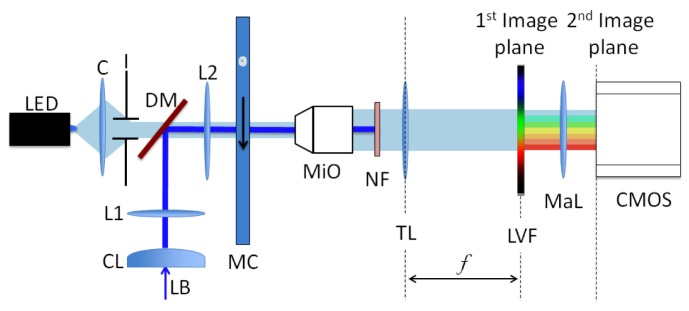
Experimental setup. A laser beam (LB) induces fluorescence in a cell flowing through the channel (MC) and is then blocked by the notch filter (NF). Fluorescence is filtered by the LVF and is then imaged onto the camera (CMOS) through a macro photography lens (MaL). The LED light, collimated by a condenser and an iris (C and I), is transmitted by a portion of the LVF and provides a bright field image of the cell. L1 and L2 form a telescopic system and MiO is a microscope objective followed by the tube lens TL.
As objects flow through the microfluidic channel, they are imaged onto different regions of the LVF and consequently are filtered by a series of bandpass filters with different center wavelengths. For a cell that is 20 μm in diameter, its magnified image is 1 mm on the LVF. Consequently, over the cell’s spatial extent, the passband of the filter changes by 9 nm, which is approximately half of the passband width. Because the passband changes by less than the filter bandwidth, we assume that the entire cell passes through a uniform filter. The spectral sampling rate is determined by the distance that the cell moves in between exposures, which depends on the cell velocity and the camera frame rate, but is between 3 nm and 5 nm in our measurements. Images are acquired by an Andor Neo sCMOS camera that has a 5.5 Mpixel (2560 × 2160) sensor and 6.5 µm pixels. Images have been acquired in global shutter mode using a region of interest of 200 × 2000 pixels. In order to have a bright field image of the objects under study, we illuminate the microfluidic channel with an LED emitting at a wavelength of 455 nm, in addition to the fluorescence excitation laser. The LVF removes the LED light except for a finite region on the side, which is used to capture a bright field image. The LED has been chosen so that its wavelength does not overlap with the sample’s fluorescence emission on the CMOS sensor.
Figure 2 shows the measurements used to calibrate our system. To characterize the spatial distribution of the fluorescence excitation beam, a solution of fluorescein in water was loaded into the microfluidic channel and illuminated with the fluorescence excitation laser. The resulting fluorescence emission was then imaged onto the camera after removing the LVF, and is shown in Fig. 2(a). The light emission is bounded in the vertical direction by the microfluidic channel walls and the brightness modulation along the horizontal direction is proportional to the distribution of the laser beam intensity. This distribution is then used for normalization, so that the measured fluorescence is independent of the excitation intensity along the channel. Figure 2(b) illustrates the calibration needed to convert the spatial distribution of the light into a spectral distribution. Two different LEDs, emitting at 505 nm and 590 nm, are filtered by the LVF, and this spatial distribution is imaged onto the camera. This calibration is performed assuming that the passband position changes linearly across the filter. The axes show the corresponding relationship between the two scales, where a wavelength range from 450 to 660 nm spans the field of view.
Fig. 2.
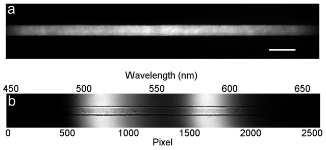
Optical calibration. a) Fluorescence emission from a solution of fluorescein in water. Scale bar is 40 µm. b) Light from two different LEDs (505 nm and 590 nm) spatially separated by the LVF.
3. High-throughput hyperspectral imaging of fluorescent beads
As a first experiment, a mixture of three different fluorescent 2 µm beads was measured using the HFM microscope [20]. The excitation/emission wavelengths of the three types are 505/515 nm, 535/575 nm and 580/605 nm, called B1, B2, and B3, respectively. Images were collected using a frame rate of 400 frame s−1 and an exposure time of 200 µs. The images were then analyzed with an algorithm for particle detection and tracking that we developed. Each bead initially passes the bright field region and is detected when the standard deviation of the intensity distribution crosses a threshold. The velocity is calculated by evaluating the position of the same bead in the following frame and is then used to track the particle in each consecutive frame. For an average velocity of 2 mm s−1, the motion blur is 400 nm and is below the diffraction limit.
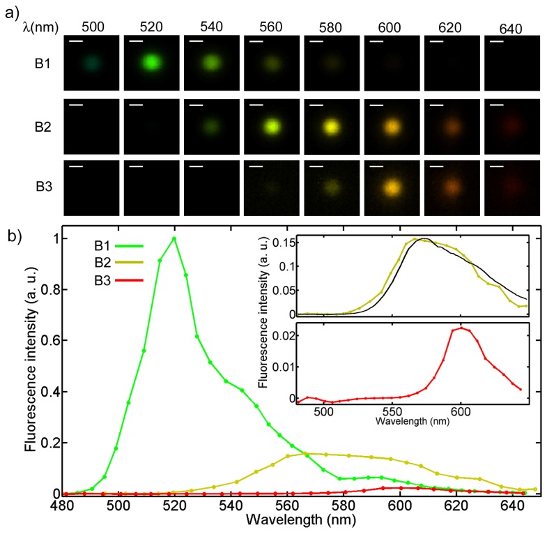
The intensity of the fluorescence signal, where present, is given by the sum of the intensity of the 40 × 40 pixels composing the image of the bead. B1 beads are the brightest of the three types, since their peak excitation wavelength is closest to the excitation laser, while the fluorescence emission from beads B2 and B3 is progressively weaker. Figure 3(a) shows images of beads of the three types, at wavelengths that are uniformly spaced between 500 nm and 640 nm with steps of 20 nm. The color added to the monochromatic images fits the corresponding wavelength and the brightness scale of each set has been normalized to its brightest image. The peak emission wavelength is clearly different between the three beads. As expected, images get noisier as the spectral distance between the excitation and the emission wavelength increases. In Fig. 3(b), a plot of the fluorescence emission is shown, where the fluorescence intensity is normalized to the highest value of bead B1. The two inserts show a second plot for beads B2 and B3 using a different scale for the fluorescence intensity. The brightest emission intensity for beads B2 and B3 is 1/6 and 1/50 of the corresponding value of bead B1. Nevertheless, both signals are easily detectable and lie in the dynamic range of the camera. The black curve plotted in the upper insert refers to the spectrum of the B2 beads acquired with a Jaz Spectrometer [10] and is plotted to show the good agreement with our result.
Fig. 3.
Hyperspectral imaging of fluorescent beads. a) Hyperspectral image set of the fluorescence emission from three types of beads. The false colors fit the corresponding wavelengths. Scale bar is 2 µm. b) Fluorescence intensity for the three types of beads as a function of the emitted wavelength. In the inserts, the plots relative to beads B2 and B3 are shown, where a different scale for the fluorescence intensity has been used. The black line refers to the spectrum for the beads B2 acquired with a spectrometer.
To investigate the accuracy and repeatability of fluorescence spectroscopy using the HFM microscope, we collected spectra of 147 beads of the three different types. Figure 4 shows a scatter plot of the fluorescence peak intensity for each bead as a function of the corresponding peak wavelength. Three separated clusters are clearly visible, referring to the three types of beads. The fluorescence peak intensity is chosen as the brightest intensity value of the retrieved bead spectrum and the corresponding wavelength estimation is thus affected by the sampling pitch, which is 5 nm. The mean values and standard deviations for the wavelength of maximum fluorescence emission are 519 ± 2 nm, 566 ± 3 nm and 602 ± 3 nm for beads B1, B2 and B3, which closely match the manufacturer’s specifications of 515, 575, and 605 nm, respectively. A smaller sampling interval or fitting of the fluorescence spectral distribution could likely reduce the standard deviation even further. The coefficients of variation for the peak intensity of beads B1, B2 and B3 are 0.07, 0.10 and 0.06 respectively.
Fig. 4.
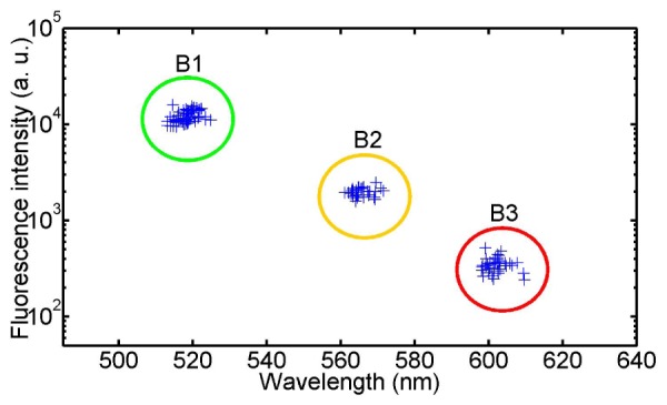
Scatter plot of the fluorescence peak intensity. The peak fluorescence intensity is plotted as a function of the peak wavelength for beads emitting at three different wavelengths. The intensity axis is on a log scale.
4. Hyperspectral imaging of fluorescently labelled cells
Hyperspectral imaging of cellular fluorescence enables analysis of the spectra of individual cellular organelles. In the first cell imaging experiment, we have used the HFM microscope to image fluorescently labeled peroxisomes inside chronic myelogenous (K562) leukemia cells using a green fluorescent protein (GFP) viral construct. Peroxisomes are cellular organelles that are responsible for breaking down fatty acids and other toxins. Mammalian cells typically have several dozen peroxisomes that are sub-micron in size and distributed in the cytoplasm. Using the HFM microscope, it is possible to spatially localize individual peroxisomes and analyze their fluorescence spectra. Figure 5(a) shows a bright field image of a cell followed by six fluorescence images at different wavelengths. As before, the brightness is normalized to the brightest image of the series and color has been added to the monochromatic images acquired by the camera. Figure 5(c) shows the fluorescence spectra of three individual peroxisomes indicated in Fig. 5(b). Each spectrum is normalized to the highest peroxisome intensity value (plotted in blue). As can be seen in the figure, the wavelength corresponding to the peak intensity is the same for all three spectra and matches the expected emission of GFP. However, using a modified GFP or other cell sensing label or ion indicator, it is possible to use the retrieved fluorescence spectra to evaluate local cellular parameters which are expected to shift the fluorescence emission spectra [4].
Fig. 5.
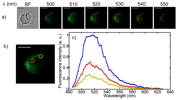
Organelle fluorescence spectroscopy. a) Bright field and six fluorescence images of GFP labeled peroxisomes inside K562 cells. The false colors fit the corresponding wavelengths. b) The fluorescence intensities of the three indicated organelles are plotted. Scale bars are 10 µm.
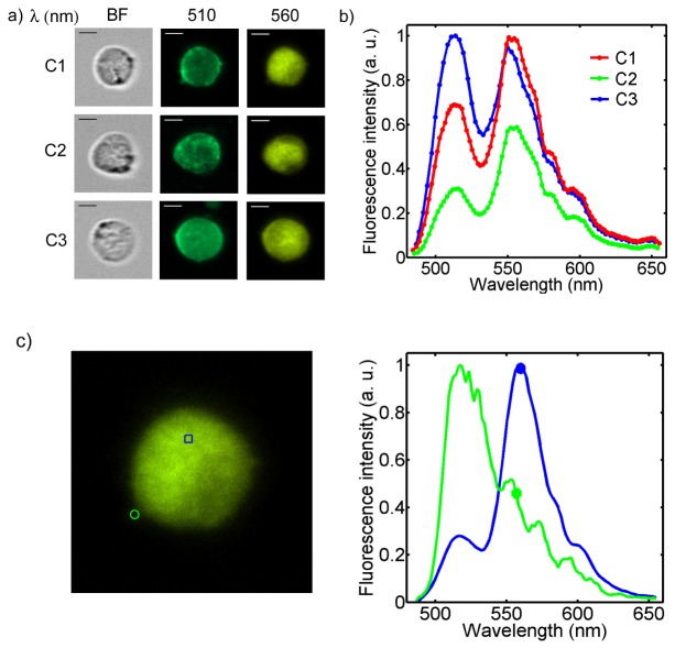
The HFM microscope can also be used to differentiate multiple fluorophores inside single cells when they emit different colors. We have labeled the membrane of acute promyelocytic leukemia cells (HL60) with PKH67, which emits green light at a peak wavelength of 504 nm [21], and labeled the cell nucleus with an orange-fluorescent stain, Syto 82 [22], which has a peak wavelength of 560 nm. In Fig. 6(a) , a bright field image and two fluorescence images at wavelengths of 510 and 560 nm are shown for three different cells. The color scale is self-normalized for each image. The plots in Fig. 6(b) show the different ratios between the membrane and the nuclear stain in the three cases. All the plots are normalized to the brightest value of fluorescent intensity. The fluorescence contribution outside the nucleus in the images at 560 nm can be due to non-specific fluorescence from the membrane stain or due to cytoplasmic and mitochondrial staining which is known to occur for Syto 82. The images captured by the HFM could be processed in order to separate overlapping fluorescence spectra using linear unmixing [23]. In Fig. 6(c) the spectra relative to the two indicated points (i.e. membrane and nucleus) are plotted (frame from Media 1 (4.9MB, MP4) ).
Fig. 6.
Multi-color fluorescence hyperspectral imaging. a) Bright field and fluorescence images at 510 and 560 nm of three HL60 cells. The false colors fit the corresponding wavelengths. Scale bars are 6 µm. b) Emitted spectra for the three cells shown in a). c) Spectra relative to the two indicated regions (Frame from Media 1 (4.9MB, MP4) ).
In all cell experiments, cells traveled through microfluidic channels that were 8 µm deep and 30 µm in width at an average velocity of 1.5 mm/s. Data was collected with the CMOS camera at a frame rate of 300 frame s−1 and an exposure time of 150 µs. In order to avoid cells settling in the inlet tube, we used a buffer composed of 18% glycerol, 12% bovine serum albumin and 70% PBS. The osmolarity of the buffer solution was adjusted to be isotonic.
5. Conclusions
In this paper, we have demonstrated a hyperspectral microscope, called the HFM microscope, for analyzing fluorescence in cells travelling through microfluidic channels. The HFM microscope has been tested on a mixture of fluorescent beads and cells that have been labeled with one and two different fluorophores. By collecting complete fluorescence spectra of cells, it might be possible to use more fluorescence labels than is possible using conventional multicolor flow cytometers. In addition, by retrieving complete spectra of individual cell organelles, chemical parameters of cells can be mapped out using fluorophores that modify their emission based on their environment. Finally, we hope that the HFM microscope will enable hyperspectral imaging to take advantage of the high throughput achievable in flow cytometry, in order to accurately characterize large samples of cells.
Acknowledgments
The authors would like to thank Dr. B. G. Hosu for his contribution for the re-imaging system equipment. Ethan Schonbrun would like to thank the Rowland Institute Junior Fellows program for supporting this work.
References and links
- 1.Stephens D. J., Allan V. J., “Light microscopy techniques for live cell imaging,” Science 300(5616), 82–86 (2003). 10.1126/science.1082160 [DOI] [PubMed] [Google Scholar]
- 2.Cheung V. G., Nowak N., Jang W., Kirsch I. R., Zhao S., Chen X.-N., Furey T. S., Kim U.-J., Kuo W.-L., Olivier M., Conroy J., Kasprzyk A., Massa H., Yonescu R., Sait S., Thoreen C., Snijders A., Lemyre E., Bailey J. A., Bruzel A., Burrill W. D., Clegg S. M., Collins S., Dhami P., Friedman C., Han C. S., Herrick S., Lee J., Ligon A. H., Lowry S., Morley M., Narasimhan S., Osoegawa K., Peng Z., Plajzer-Frick I., Quade B. J., Scott D., Sirotkin K., Thorpe A. A., Gray J. W., Hudson J., Pinkel D., Ried T., Rowen L., Shen-Ong G. L., Strausberg R. L., Birney E., Callen D. F., Cheng J. F., Cox D. R., Doggett N. A., Carter N. P., Eichler E. E., Haussler D., Korenberg J. R., Morton C. C., Albertson D., Schuler G., de Jong P. J., Trask B. J., BAC Resource Consortium , “Integration of cytogenetic landmarks into the draft sequence of the human genome,” Nature 409(6822), 953–958 (2001). 10.1038/35057192 [DOI] [PMC free article] [PubMed] [Google Scholar]
- 3.Lippincott-Schwartz J., Patterson G. H., “Development and use of fluorescent protein markers in living cells,” Science 300(5616), 87–91 (2003). 10.1126/science.1082520 [DOI] [PubMed] [Google Scholar]
- 4.Kneen M., Farinas J., Li Y., Verkman A. S., “Green fluorescent protein as a noninvasive intracellular pH indicator,” Biophys. J. 74(3), 1591–1599 (1998). 10.1016/S0006-3495(98)77870-1 [DOI] [PMC free article] [PubMed] [Google Scholar]
- 5.Minta A., Kao J. P., Tsien R. Y., “Fluorescent indicators for cytosolic calcium based on rhodamine and fluorescein chromophores,” J. Biol. Chem. 264(14), 8171–8178 (1989). [PubMed] [Google Scholar]
- 6.Owen D. M., Williamson D. J., Magenau A., Gaus K., “Sub-resolution lipid domains exist in the plasma membrane and regulate protein diffusion and distribution,” Nat Commun 3, 1256 (2012). 10.1038/ncomms2273 [DOI] [PubMed] [Google Scholar]
- 7.Perfetto S. P., Chattopadhyay P. K., Roederer M., “Seventeen-colour flow cytometry: unravelling the immune system,” Nat. Rev. Immunol. 4(8), 648–655 (2004). 10.1038/nri1416 [DOI] [PubMed] [Google Scholar]
- 8.Grégori G., Patsekin V., Rajwa B., Jones J., Ragheb K., Holdman C., Robinson J. P., “Hyperspectral cytometry at the single-cell level using a 32-channel photodetector,” Cytometry A 81(1), 35–44 (2012). 10.1002/cyto.a.21120 [DOI] [PubMed] [Google Scholar]
- 9.Basiji D. A., Ortyn W. E., Liang L., Venkatachalam V., Morrissey P., “Cellular image analysis and imaging by flow cytometry,” Clin. Lab. Med. 27(3), 653–670, viii (2007). 10.1016/j.cll.2007.05.008 [DOI] [PMC free article] [PubMed] [Google Scholar]
- 10.Item LVF-HL, Ocean Optics, Catalogue of Products.
- 11.Haraguchi T., Ding D. Q., Yamamoto A., Kaneda T., Koujin T., Hiraoka Y., “Multiple-color fluorescence imaging of chromosomes and microtubules in living cells,” Cell Struct. Funct. 24(5), 291–298 (1999). 10.1247/csf.24.291 [DOI] [PubMed] [Google Scholar]
- 12.Woltman S. J., Jay G. D., Crawford G. P., “Liquid-crystal materials find a new order in biomedical applications,” Nat. Mater. 6(12), 929–938 (2007). 10.1038/nmat2010 [DOI] [PubMed] [Google Scholar]
- 13.Levenson R. M., “Spectral imaging perspective on cytomics,” Cytometry A 69(7), 592–600 (2006). 10.1002/cyto.a.20292 [DOI] [PubMed] [Google Scholar]
- 14.Sinclair M. B., Haaland D. M., Timlin J. A., Jones H. D., “Hyperspectral confocal fluorescence imaging: exploring alternative multivariate curve resolution approaches,” Appl. Opt. 45, 6283–6291 (2006). 10.1364/AO.45.006283 [DOI] [PubMed] [Google Scholar]
- 15.Matsuoka H., Kosai Y., Saito M., Takeyama N., Suto H., “Single-cell viability assessment with a novel spectro-imaging system,” J. Biotechnol. 94(3), 299–308 (2002). 10.1016/S0168-1656(01)00431-X [DOI] [PubMed] [Google Scholar]
- 16.Gao L., Kester R. T., Hagen N., Tkaczyk T. S., “Snapshot image mapping spectrometer (IMS) with high sampling density for hyperspectral microscopy,” Opt. Express 18(14), 14330–14344 (2010). 10.1364/OE.18.014330 [DOI] [PMC free article] [PubMed] [Google Scholar]
- 17.Schmidt O., Bassler M., Kiesel P., Knollenberg C., Johnson N., “Fluorescence spectrometer-on-a-fluidic-chip,” Lab Chip 7(5), 626–629 (2007). 10.1039/b618879f [DOI] [PubMed] [Google Scholar]
- 18.Gorthi S. S., Schonbrun E., “Phase imaging flow cytometry using a focus-stack collecting microscope,” Opt. Lett. 37(4), 707–709 (2012). 10.1364/OL.37.000707 [DOI] [PubMed] [Google Scholar]
- 19.Schonbrun E., Gorthi S. S., Schaak D., “Microfabricated multiple field of view imaging flow cytometry,” Lab Chip 12(2), 268–273 (2011). 10.1039/c1lc20843h [DOI] [PubMed] [Google Scholar]
- 20.FluoroSpheres, Carboxylate-modified microsphere, Invitrogen
- 21.Sigma Aldrich, Catalogue of Products.
- 22.Nucleic Acid Cell Stains, Invitrogen
- 23.Zimmermann T., “Spectral imaging and linear unmixing in light microscopy,” Adv. Biochem. Eng. Biotechnol. 95, 245–265 (2005). 10.1007/b102216 [DOI] [PubMed] [Google Scholar]


