Abstract
Optical coherence tomography (OCT) has a tremendous global impact upon the ability to diagnose, treat, and monitor eye diseases. A miniature 25-gauge forward-imaging OCT probe with a disposable tip was developed for real-time intraoperative ocular imaging of posterior pole and peripheral structures to improve vitreoretinal surgery. The scanning range was 2 mm when the probe tip was held 3-4 mm from the tissue surface. The axial resolution was 4-6 µm and the lateral resolution was 25-35 µm. The probe was used to image cellophane tape and multiple ocular structures.
OCIS codes: (170.4500) Optical coherence tomography, (120.3890) Medical optics instrumentation
1. Introduction
Optical coherence tomography is used daily in ophthalmology clinics to evaluate the delicate structures within the eye for evidence of macular edema, macular holes, subtle retinal lesions, glaucomatous retinal nerve fiber thinning, etc. Optical coherence tomography has evolved from time-domain to spectral-domain imaging with improved imaging speed and resolution [1] of the retinal layers [2–4]. Multiple OCT systems in clinical use image structures, including the macula, optic nerve, retinal nerve fiber, and choroid, confined to the posterior pole, but lack the ability to image peripheral structures. Also, distortions or opacities in a subject's ocular media, such as a dense cataract, will reduce the OCT signal delivered externally and may prevent adequate images [5].
Probes provide one mechanism to bypass opacities or to directly view structures that otherwise cannot be imaged directly with an external OCT system. A forward-viewing intraocular OCT probe with the capability for real-time cross-sectional retinal imaging would be advantageous for intraoperative diagnosis and surgery. For example, it would permit cross-sectional profiles of the extent of epiretinal membranes and enable surgeons to determine if their membrane peeling was satisfactorily completed prior to removing the instruments. This is a major concern of vitreoretinal surgeons and a deficiency of current techniques despite the use of potentially toxic dyes to visualize the membranes [6,7]. A small B-scan probe with high resolution would be required to fit through the 25-gauge vitrectomy ports currently preferred by vitreoretinal surgeons.
Large [8–10] and small [11,12] OCT side-scanning probes have been developed to examine tissues within tubular structures such as the esophagus and coronary arteries with lateral resolution up to 10 µm. Probes as small as 0.36 mm have been developed, but they also acquire views from the side rather than directly in front of the catheter tip [13]. However, a forward-imaging probe is optimal for viewing the inner layer of a hollow organ, such as within the eye to evaluate the retina, through a standard surgical entry port. A forward-imaging OCT device has been used to image bladders, but its diameter is relatively large, measuring 5.8 mm X 3 mm [14]. The standard microelectromechanical system (MEMS) scanning mirror component of an OCT forward-imaging probe has been reduced to a diameter of 1 mm [15], but just the mirror alone is still larger than the currently used 23-gauge (0.64 mm) or 25-gauge (0.51 mm) ophthalmic intraocular surgical instruments. Others have used a piezoelectric cantilever system with a rod lens 2.7 mm in diameter [16], a lead zirconate titanate actuator and cantilever within a 2.4 mm diameter probe [17], a fiber-bundle system measuring 3.2 mm in diameter [18], paired rotating GRIN lenses in a probe measuring 1.65 mm in diameter [19], an electrostatic scanning probe measuring 2.2 mm in diameter [20], and an electrostatic scanning probe measuring 2 mm in diameter [21]. A 21-gauge (0.82 mm diameter) forward-imaging probe was previously designed with two counter-rotating angle polished GRIN lenses with scanning speed of 0.5 Hz, lateral resolution of 7.6 to 10.4 µm, and axial resolution of 7.8 to 10.5 µm [22]. This probe’s speed is much slower than video rate. Thus, it would be difficult to clearly image motion during surgical procedures in real-time, and the probe is too large to fit through the sizes of the current vitrectomy ports. To address the size challenge needed for the now standard vitrectomy ports accommodating 23-gauge (0.64 mm) and 25-gauge (0.51 mm) instruments, using the individual OCT A-scan components alone would permit miniaturization of the sensing probe. Iftimia, et al. developed a 1310 nm center wavelength OCT A-scan imaging system to measure depth-resolved information in solid tissues for fine needle biopsy guidance [23]. This 250 µm diameter probe has a simple and robust design to elegantly detect the presence of two tissue types and the interface between them in a single A-scan. It is capable of being introduced into a microsurgical biopsy needle to assist in obtaining optimal specimens. However, this design is unable to provide 2-dimensional information unless the entire needle moves to produce a scan [24,25]. A 25-gauge (0.51 mm) common-path OCT probe has been developed [24,25]. However, the probe tip must be positioned within 1.6 mm of a delicate tissue, such as retina, with scanning of the entire probe without touching the easily damaged tissue to produce 33 µm lateral resolution images at a sampling rate of 460 A-scans per second [25].
Alternative designs for permitting scanning within miniature probes as described in this paper are required to fit within the current standard vitrectomy and permit intraoperative OCT imaging of small tissues and organs such as the eye at safe distances from the easily damaged tissues. We report the smallest self-contained 25-gauge (0.51 mm) handheld forward-imaging B-scan OCT probe and demonstrate its feasibility for ophthalmic examination. The described miniature probe will easily pass through the now standard 23-gauge (0.64 mm) and 25-gauge (0.51 mm) instrument ports to permit intraocular imaging during surgery. All previously reported self-contained scanning forward-imaging probes are too large to pass through these ports. In addition, an intraocular OCT probe would permit evaluation of structures, such as the peripheral retina and ciliary body, beyond the central 30 degree posterior pole of the globe.
2. Probe design and technical performance
2.1 Design
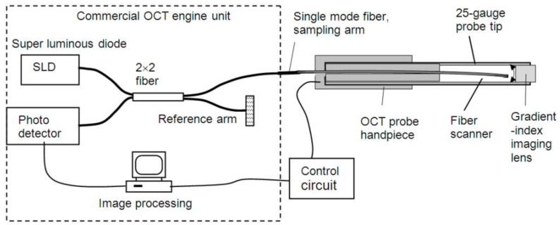
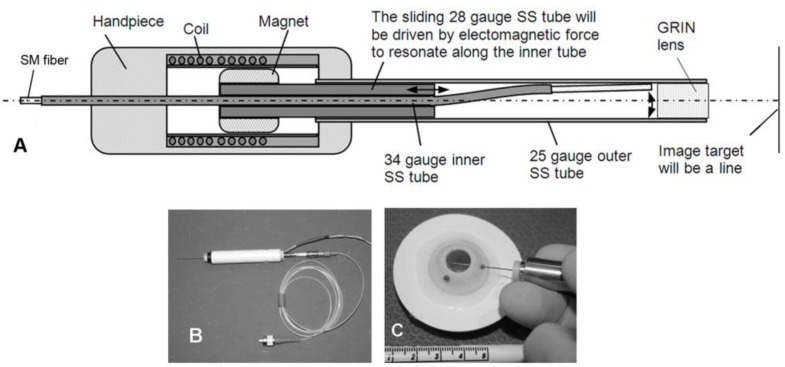
A commercial high-resolution spectral-domain optical coherence tomography (SDOCT) system (Bioptigen, Inc. Durham, NC) is used to provide the SLD source, interferometer, spectrometer, and image processing (Fig. 1 ). The central wavelength is 870 nm, the SLD light source spectral width is 90 nm, the scanning rate is 5 Hz with 2000 A-scans per B-scan, and the maximum optical power is 700 µW from the spectral domain OCT (SDOCT). The sampling arm fiber is placed within the miniature forward-imaging intraocular OCT probe. The outer diameter of the hand piece is 12 mm, and the length of the hand piece is 10 cm. The probe’s sampling arm fiber scanner is driven by an electronic circuit that is synchronized with the Bioptigen engine. The detailed structure of the miniature intraocular OCT probe is shown in Fig. 2(a) and its external appearance is shown in Fig. 2(b) and Fig. 2(c).
Fig. 1.
Diagram of the OCT probe system.
Fig. 2.
(a) Configuration of the miniature forward-imaging OCT probe. (b) External appearance of one 25-gauge OCT probe. (c) The probe easily passes through a 25-gauge vitrectomy port.
The disposable 25-gauge extra-thin-wall probe tip (outer diameter = 0.51 mm, wall thickness = 70 μm, and length = 30 mm beyond the end of the handpiece) has a sealed 0.35 mm diameter GRIN lens (Go!Foton, Somerset, NJ) attached in front which protects the fiber scanner. The customized GRIN lens is 0.5 mm thick, which is less than ¼ pitch, to enable a chosen working distance of 3 to 4 mm from the outer surface of the GRIN lens to the target. The cannula also protects the end of the sampling arm which is a 125 μm single mode fiber. The fiber tip scans behind the GRIN image lens. The distance between the fiber tip and the inner surface of the GRIN lens is approximately 200 μm.
The single-mode fiber is housed within a 34-gauge extra-thin-wall stainless steel tube. The fiber tip protrudes from the tube between 2 to 3 mm. The front portion of the 34-gauge tube is bent into a smoothed “S” shape. The mechanism to produce the scanning of the fiber tip is formed by sliding a straight 28-gauge thin-wall stainless steel tube along the curved part of the 34-gauge tube. The gap between the tubes is lubricated with silicone oil (Frankhillson Co., Cupertino, CA). When the 28-gauge tube slides along the 34-gauge tube, it forces the tip of the 34-gauge tube to scan laterally as shown in Fig. 2(a) within an air-filled space. The specific dimensions of the tubing within the OCT probe are: 25-gauge outer diameter (O.D.) = 0.51 mm, inner diameter (I.D.) = 0.38 mm; 28-gauge O.D. = 0.36 mm, I.D. = 0.22 mm; and 34-gauge O.D. = 0.20 mm, I.D. = 0.14 mm. The entire tip easily passes through a standard 25-gauge vitrectomy port as shown in Fig. 2(c).
2.2 Technical performance
The SDOCT fiber-scanning probe transmitted power of 700 µW from the SDOCT system. Each B-scan consists of 2000 A-scans generated by the SDOCT system (Bioptigen, Inc., Durham, NC). When a ±10 V triangle wave was applied to the probe, a 2 mm B-scan scanning range of the target was achieved at a working distance of 3 to 4 mm from the probe tip. The scanning frequency and the lateral resolution of the probe were determined.
2.2.1 Scanning frequency
The customized coil magnetic system was designed and fabricated. The driving force of the 28-gauge tube is a coil-magnetic oscillator built within the hand piece. The ±10 V triangle wave is synchronized to the Bioptigen engine to drive the electromagnetic coil. A magnet is connected to the distal end of the 28-gauge tube which slides forward and back as current alternates through the coil. When the 28-gauge stainless tube is driven to slide a distance of approximately 3 mm, the fiber tip will scan about 0.2 mm laterally behind the GRIN lens. The scanning frequency was measured to be 5 Hz. The 34-gauge tube was polished with 0.3 µm grit optical polishing film and lubricated with silicone oil (Frankhillson Co., Cupertino, CA) to ensure smoothness in scanning. Smoothness of the linear scanning was visually judged by lack of jittering of the screen image. Some distortion will occur at the edges of the images due to non-linear scanning speed as the fiber changes direction within the probe. The beam scan increases linearly from 1 mm to 2 mm as the voltage is increased from 8 V to 10 V, the beam scan increases nonlinearly as the voltage is increased from 5 V to 8 V, and the beam does not scan below 5 V. The probe can go up to 20 Hz by increasing the AC frequency. However, image display was optimal when synchronized with the Bioptigen system at 5 Hz to match its data acquisition speed.
2.2.2. Lateral resolution calculation
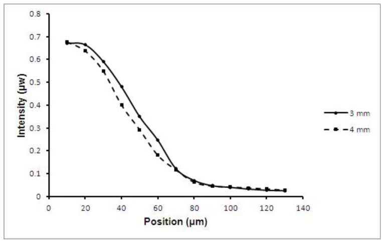
The full width at half maximum (FWHM) of an infrared beam can be measured by the knife-edge method to calculate lateral resolution [26]. A blade is moved at known intervals across a beam and the resulting power is measured at each step. The results of knife-edge measurement of the focused IR beam at the central position of the scan are graphed in Fig. 3 below. This corresponds to the central lateral resolution of the OCT probe. The spot size measurement at a distance of 3 mm (solid line) from the lens was 25 µm and the spot size measurement at a distance of 4 mm (dashed line) from the lens was 30 µm. The full width at half maximum (FWHM) was also measured by the knife-edge technique at the lateral position of the scan. The lateral resolution at this position was calculated to change 17% to 35 µm at a working distance of 4 mm. The Gaussian beam waist size for the customized GRIN lens was 25 µm at 3 mm distance from the lens. Currently, the maximum average irradiance of one scan pass 2 mm long was 1.4 W/cm2 over 0.1 s. The time duration at each spot was 1.25 ms. The average irradiance extensively decreases as the probe is moved like the vitrectomy light pipe or the intraocular endoscope over at least a 1 cm2 area.
Fig. 3.
The OCT beam spot-size from the forward-imaging probe was calculated by the knife-edge method. The spot size measurements at a distance of 3 mm (solid line) and at a distance of 4 mm (dashed line) are graphed.
3. Testing of the miniature probe for OCT imaging
To demonstrate the imaging capabilities of the miniature OCT probe, infrared paper, a roll of cellophane tape and intact cadaver porcine ocular tissues were imaged.
3.1 OCT imaging of infrared paper
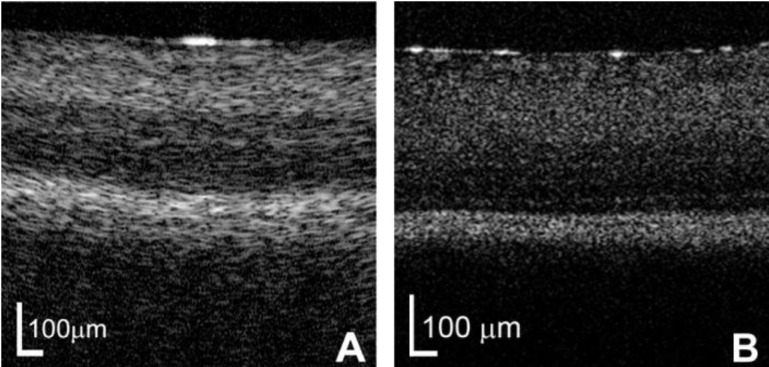
An image of an infrared viewing card (VRC5, Thorlabs, NJ) taken by the probe at 5 Hz is shown in Fig. 4 . The top layer is a plastic film overlaying the infrared photosensitive layer of the card.
Fig. 4.
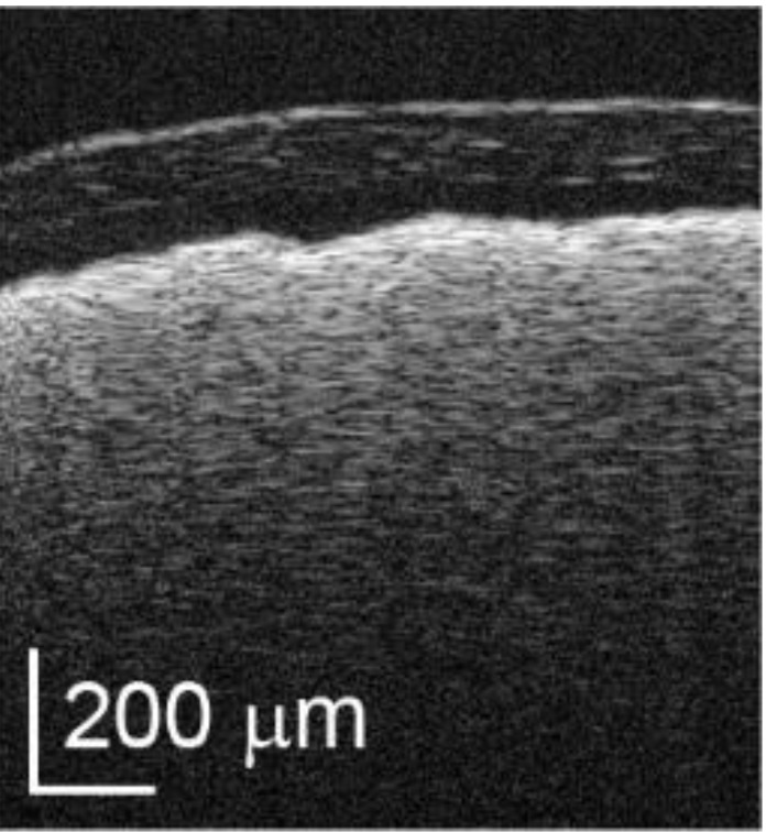
OCT probe image of an IR card taken at 5 Hz.
3.2 OCT imaging of cellophane tape phantom
A single real-time image of a roll of cellophane tape is shown in Fig. 5(a) to demonstrate the ability of the miniature forward-imaging OCT probe. Each tape layer including the glue space is 50 μm. The axial resolution of the probe appears similar to the axial resolution of the commercial tissue-imaging probe shown in Fig. 5(b), which is reported to be 4 to 6 μm near the spectral limit of the Bioptigen, Inc. very-high resolution SLD source.
Fig. 5.
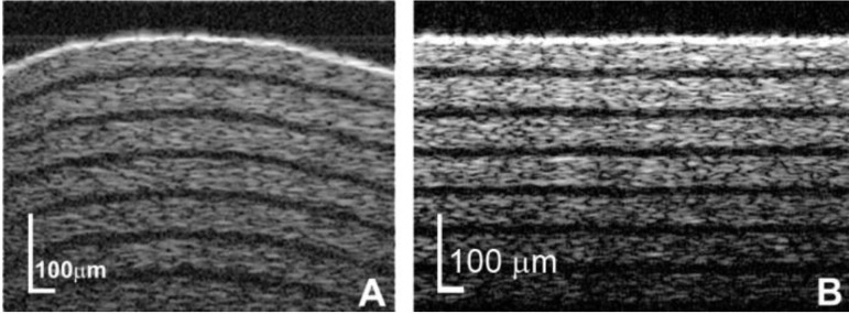
(a) Multiple layers within a roll of cellophane tape are clearly delineated by the miniature OCT probe. (b) Similarly, multiple layers are visible when imaged with a commercial 18 mm diameter probe.
3.3 OCT imaging of porcine ocular tissue
To test the performance of the probe for real-time non-averaged imaging of ocular structures, fresh porcine eyes were used. The B-scan probe was aimed externally at the eyelid skin, cornea, and conjunctiva as shown in Fig. 6 . It was possible to identify the underlying layers of Tenons and sclera beneath the underling superficial conjunctiva as shown in Fig. 6(c).
Fig.6.
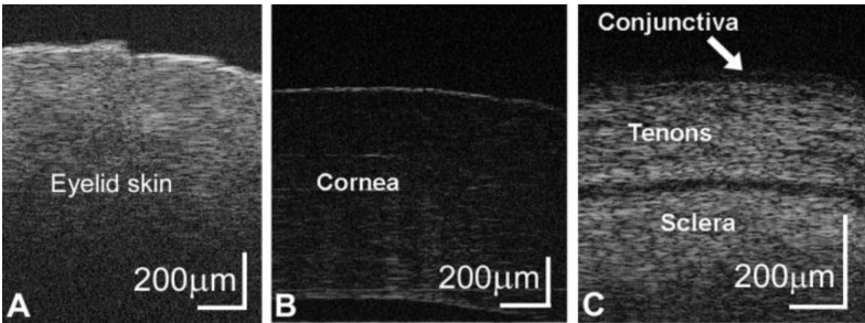
Real-time images of (a) eyelid skin, (b) cornea, and (c) conjunctiva. (b) The outer corneal epithelium and inner Descemets membrane are visible in the corneal images. (c) The layers of conjunctiva and Tenons are observed above the dense sclera.
The probe’s working distance also permitted real-time imaging of the iris and lens surface as shown in Fig. 7(a) and Fig. 7(b) through an intact cornea. Opening the cornea permitted imaging of the peripheral angle with angulation of the probe in the anterior chamber as shown in a single unprocessed frame in Fig. 7(c).
Fig.7.
The cross-section of the (a) iris is visible including its relationship to the (b) lens surface. (c) The anterior chamber angle structures are visible with the miniature OCT probe.
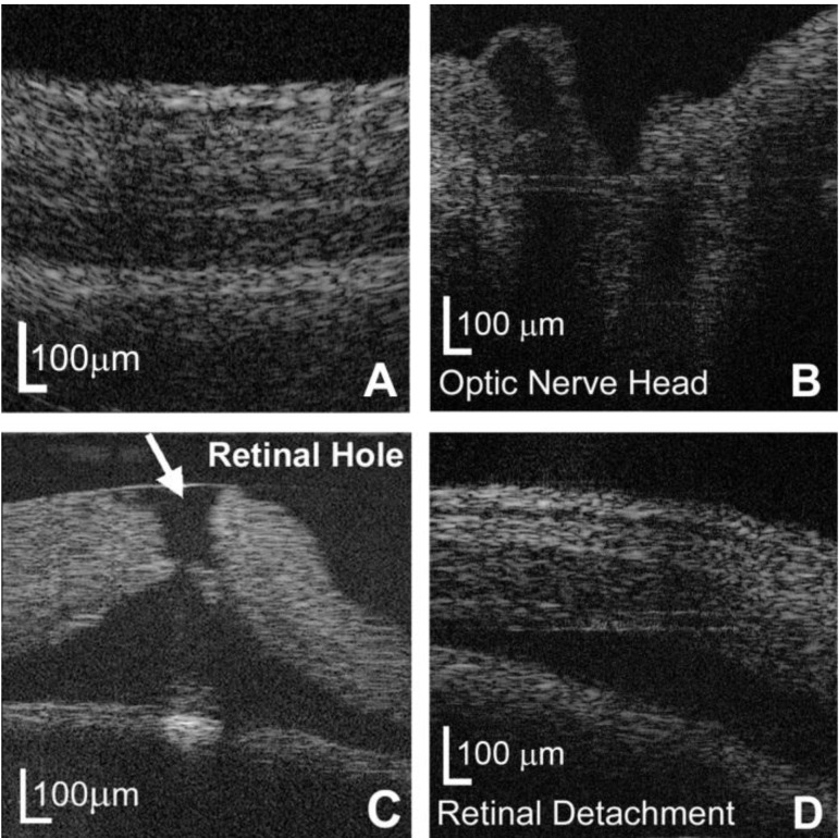
Removal of the lens and vitreous was performed to ensure that the probe was held within 3 to 4 mm of the retina to test the probe’s capabilities within the range of its known calculated lateral resolution. A real-time B-scan image of the porcine retina is shown in Fig. 8(a) . Several layers of the retina could be clearly identified as demonstrated in this individual frame from the real-time video. The probe was able to image the cross-sectional appearance of the porcine optic nerve as shown in Fig. 8(b). A retinal hole was successfully imaged in Fig. 8(c). Balanced saline solution was injected under the retina to model a retinal detachment which was successfully imaged in Fig. 8(d). Layers within cadaver porcine retina are similarly observed with the miniature OCT probe Fig. 9(a) and with the large commercial 18 mm diameter tissue-imaging probe Fig. 9(b).
Fig. 8.
The miniature intraocular probe is able to (a) distinguish layers of the retina, (b) image the optic nerve in a porcine eye, (c) image a retinal hole, and (d) visualize a retinal detachment.
Fig. 9.
(a) Several layers within a porcine cadaver retina are delineated by the miniature OCT probe. (b) Similarly, several layers are visible within a porcine cadaver retina when imaged with a commercial 18 mm diameter probe.
4. Discussion and conclusion
A miniature hand-held 25-gauge probe was developed to obtain high-resolution SDOCT two-dimensional imaging of intraocular structures. Its diameter is compatible with the smallest commercially-available vitrectomy port system to permit real-time, non-averaged, intraoperative depth-resolved images of intraocular structures. Simply pointing the probe at the area of interest will produce a B-scan image of the structure. The quality of the retinal images (Fig. 8 and Fig. 9) also is at least as good as the quality of images of porcine cadaver retinas produced from a microscope-integrated OCT system developed by Hahn, et al. [27].
The value of OCT imaging in the ophthalmic operating room has been demonstrated with an external system in evaluating the changes of the retinal structures immediately following surgical manipulation [27–33]. This would ensure that the intended procedure has been completed as desired. Additional steps could be undertaken if the procedure was found to be incomplete, whereas a second surgery would have to be scheduled if an incomplete procedure was discovered postoperatively during the clinic examination. However, it would be most desirable to use real-time intraoperative OCT to improve efficiency and completeness interactively during a procedure, such as during membrane peeling, by aiding visualization of the actual surgical maneuvers as they occur. External OCT has limitations in that metallic surgical instruments cast dense optical shadows upon the underlying tissues of interest [27–29,31]. In addition, a major limitation is the ability to efficiently locate and follow the surgical instrument as the membrane peeling or other procedure occurs [27–29]. Finally, optical aberrations of the media will reduce clarity of the externally acquired OCT image [5]. An intraocular OCT probe would solve these limitations posed by external OCT imaging. In addition, an intraocular OCT probe could be positioned to image structures in the periphery of the eye which are not accessible by external OCT imaging.
Unlike other miniature forward-imaging probes, this probe has an internal scanning system so that the entire probe itself does not need to be scanned back-and-forth to obtain two-dimensional images. This feature is immensely important. It permits the 25-gauge probe to be handled by the retina surgeon in a manner similar to other intraocular instruments. Bypassing the need for moving the entire probe 1.6 mm or closer to tissue to produce a B-scan also avoids the risk of damage to the entrance port and/or the retina. The probe length was designed to encompass the distance between the surgeon’s hand and the target. The focusing distance of the GRIN lens can be modified to accommodate a different desired working distance from the tissue.
The 25-gauge forward-imaging probe with its disposable tip is compatible with the increasingly popular 25-gauge ports for vitrectomy. Other previously described self-contained scanning OCT probes are too large to pass through the now standard 23-gauge and 25-gauge vitrectomy ports used in retinal surgery. The fluid impervious tip permits imaging in fluids such as the BSS used during a vitrectomy. Disposable tips permit the probe body to be re-sterilized and used in other surgical cases similar to a phacoemulsification hand piece used to remove cataracts. When combined with an OCT system, this probe permits the operator to point at desired locations to produce real-time depth-imaging of that intraocular anatomical structure. Retinal layers and blood vessels become visible. Future plans include interactive visualization within a living eye, and visualization of an epiretinal membrane model during removal of the membrane. Eliminating the need for potentially toxic visualization dyes as well as ensuring that the entire membrane is removed would improve epiretinal membrane procedures [6,7]. This probe has the potential to provide real-time evaluation of intraocular tissues to guide surgical maneuvers in the future.
Acknowledgments
The authors acknowledge the support of: NIH 1R21EY019752, Joseph Ellis Family Research Fund, William Black Research Fund, Vanderbilt Vision Research Center P30EY00812, and Unrestricted Grant from Research to Prevent Blindness, Inc., N.Y. to the Vanderbilt Eye Institute. The authors would like to thank Haoran Yu for technical support.
References and links
- 1.Sarunic M. V., Applegate B. E., Izatt J. A., “Spectral domain second-harmonic optical coherence tomography,” Opt. Lett. 30(18), 2391–2393 (2005). 10.1364/OL.30.002391 [DOI] [PubMed] [Google Scholar]
- 2.Nassif N., Cense B., Park B. H., Yun S. H., Chen T. C., Bouma B. E., Tearney G. J., de Boer J. F., “In vivo human retinal imaging by ultrahigh-speed spectral domain optical coherence tomography,” Opt. Lett. 29(5), 480–482 (2004). 10.1364/OL.29.000480 [DOI] [PubMed] [Google Scholar]
- 3.Tao Y. K., Zhao M., Izatt J. A., “High-speed complex conjugate resolved retinal spectral domain optical coherence tomography using sinusoidal phase modulation,” Opt. Lett. 32(20), 2918–2920 (2007). 10.1364/OL.32.002918 [DOI] [PubMed] [Google Scholar]
- 4.Stopa M., Bower B. A., Davies E., Izatt J. A., Toth C. A., “Correlation of pathologic features in spectral domain optical coherence tomography with conventional retinal studies,” Retina 28(2), 298–308 (2008). 10.1097/IAE.0b013e3181567798 [DOI] [PubMed] [Google Scholar]
- 5.Savini G., Zanini M., Barboni P., “Influence of pupil size and cataract on retinal nerve fiber layer thickness measurements by Stratus OCT,” J. Glaucoma 15(4), 336–340 (2006). 10.1097/01.ijg.0000212244.64584.c2 [DOI] [PubMed] [Google Scholar]
- 6.Almony A., Nudleman E., Shah G. K., Blinder K. J., Eliott D. B., Mittra R. A., Tewari A., “Techniques, rationale, and outcomes of internal limiting membrane peeling,” Retina 32(5), 877–891 (2012). 10.1097/IAE.0b013e318227ab39 [DOI] [PubMed] [Google Scholar]
- 7.Carpentier C., Zanolli M., Wu L., Sepulveda G., Berrocal M. H., Saravia M., Diaz-Llopis M., Gallego-Pinazo R., Filsecker L., Verdaguer-Diaz J. I., Milan-Navarro R., Arevalo J. F., Maia M., “Residual internal limiting membrane after epiretinal membrane peeling: Results of the Pan-American Collaborative Retina Study Group,” Retina (Apr): 22 (2013) (Epub ahead of print) [DOI] [PubMed] [Google Scholar]
- 8.Rollins A. M., Ung-Arunyawee R., Chak A., Wong R. C., Kobayashi K., Sivak M. V., Jr, Izatt J. A., “Real-time in vivo imaging of human gastrointestinal ultrastructure by use of endoscopic optical coherence tomography with a novel efficient interferometer design,” Opt. Lett. 24(19), 1358–1360 (1999). 10.1364/OL.24.001358 [DOI] [PubMed] [Google Scholar]
- 9.Klein A. M., Pierce M. C., Zeitels S. M., Anderson R. R., Kobler J. B., Shishkov M., de Boer J. F., “Imaging the human vocal folds in vivo with optical coherence tomography: a preliminary experience,” Ann. Otol. Rhinol. Laryngol. 115(4), 277–284 (2006). [DOI] [PubMed] [Google Scholar]
- 10.Wong B. J. F., Jackson R. P., Guo S., Ridgway J. M., Mahmood U., Su J., Shibuya T. Y., Crumley R. L., Gu M., Armstrong W. B., Chen Z., “In vivo optical coherence tomography of the human larynx: normative and benign pathology in 82 patients,” Laryngoscope 115(11), 1904–1911 (2005). 10.1097/01.MLG.0000181465.17744.BE [DOI] [PubMed] [Google Scholar]
- 11.Low A. F., Tearney G. J., Bouma B. E., Jang I. K., “Technology Insight: optical coherence tomography--current status and future development,” Nat. Clin. Prac. Cardiovasc. Med. 3(3), 154–162, quiz 172 (2006). 10.1038/ncpcardio0482 [DOI] [PubMed] [Google Scholar]
- 12.Kawasaki M., Bouma B. E., Bressner J., Houser S. L., Nadkarni S. K., MacNeill B. D., Jang I. K., Fujiwara H., Tearney G. J., “Diagnostic accuracy of optical coherence tomography and integrated backscatter intravascular ultrasound images for tissue characterization of human coronary plaques,” J. Am. Coll. Cardiol. 48(1), 81–88 (2006). 10.1016/j.jacc.2006.02.062 [DOI] [PubMed] [Google Scholar]
- 13.Jafri M. S., Tang R., Tang C. M., “Optical coherence tomography guided neurosurgical procedures in small rodents,” J. Neurosci. Methods 176(2), 85–95 (2009). 10.1016/j.jneumeth.2008.08.038 [DOI] [PubMed] [Google Scholar]
- 14.Pan Y. T., Xie T. Q., Du C. W., Bastacky S., Meyers S., Zeidel M. L., “Enhancing early bladder cancer detection with fluorescence-guided endoscopic optical coherence tomography,” Opt. Lett. 28(24), 2485–2487 (2003). 10.1364/OL.28.002485 [DOI] [PubMed] [Google Scholar]
- 15.Jain A., Kopa A., Pan Y., Fedder G. K., Xie H., “A two-axis electrothermal micromirror for endoscopic optical coherence tomography,” IEEE J. Sel. Top. Quantum Electron. 10(3), 636–642 (2004). 10.1109/JSTQE.2004.829194 [DOI] [Google Scholar]
- 16.Boppart S. A., Bouma B. E., Pitris C., Tearney G. J., Fujimoto J. G., Brezinski M. E., “Forward-imaging instruments for optical coherence tomography,” Opt. Lett. 22(21), 1618–1620 (1997). 10.1364/OL.22.001618 [DOI] [PubMed] [Google Scholar]
- 17.Liu X., Cobb M. J., Chen Y., Kimmey M. B., Li X., “Rapid-scanning forward-imaging miniature endoscope for real-time optical coherence tomography,” Opt. Lett. 29(15), 1763–1765 (2004). 10.1364/OL.29.001763 [DOI] [PubMed] [Google Scholar]
- 18.Xie T., Mukai D., Guo S., Brenner M., Chen Z., “Fiber-optic-bundle-based optical coherence tomography,” Opt. Lett. 30(14), 1803–1805 (2005). 10.1364/OL.30.001803 [DOI] [PubMed] [Google Scholar]
- 19.Wu J., Conry M., Gu C., Wang F., Yaqoob Z., Yang C., “Paired-angle-rotation scanning optical coherence tomography forward-imaging probe,” Opt. Lett. 31(9), 1265–1267 (2006). 10.1364/OL.31.001265 [DOI] [PubMed] [Google Scholar]
- 20.Munce N. R., Mariampillai A., Standish B. A., Pop M., Anderson K. J., Liu G. Y., Luk T., Courtney B. K., Wright G. A., Vitkin I. A., Yang V. X. D., “Electrostatic forward-viewing scanning probe for Doppler optical coherence tomography using a dissipative polymer catheter,” Opt. Lett. 33(7), 657–659 (2008). 10.1364/OL.33.000657 [DOI] [PubMed] [Google Scholar]
- 21.Sun C., Lee K. K. C., Vuong B., Cusimano M. D., Brukson A., Mauro A., Munce N., Courtney B. K., Standish B. A., Yang V. X. D., “Intraoperative handheld optical coherence tomography forward-viewing probe: physical performance and preliminary animal imaging,” Biomed. Opt. Express 3(6), 1404–1412 (2012). 10.1364/BOE.3.001404 [DOI] [PMC free article] [PubMed] [Google Scholar]
- 22.Han S., Sarunic M.V., Wu J., Humayun M., Yang C., “Handheld forward-imaging needle endoscope for ophthalmic optical coherence tomography inspection,” J. Biomed. Opt. 13(2), 020505 (2008). [DOI] [PubMed] [Google Scholar]
- 23.Iftimia N.V., Bouma B.E., Pitman M.B., Goldberg B., Bressner J., Tearney G.J., “A portable, low coherence interferometry based instrument for fine needle aspiration biopsy guidance,” Rev. Sci. Instrum. 76(6), 064301 (2005). [Google Scholar]
- 24.Yang S., Balicki M., MacLachlan R. A., Liu X., Kang J. U., Taylor R. H., Riviere C. N., “Optical coherence tomography scanning with a handheld vitreoretinal micromanipulator,” in Proceedings of 2012 Annual International Conference of the IEEE Engineering in Medicine and Biology Society (IEEE, 2012), pp. 948–951 10.1109/EMBC.2012.6346089 [DOI] [PMC free article] [PubMed] [Google Scholar]
- 25.Huang Y., Liu X., Song C., Kang J. U., “Motion-compensated hand-held common-path Fourier-domain optical coherence tomography probe for image-guided intervention,” Biomed. Opt. Express 3(12), 3105–3118 (2012). 10.1364/BOE.3.003105 [DOI] [PMC free article] [PubMed] [Google Scholar]
- 26.Wright D., Greve P., Fleischer J., Austin L., “Laser beam width, divergence and beam propagation factor: an international standardization approach,” Opt. Quantum Electron. 24(9), S993–S1000 (1992). 10.1007/BF01588600 [DOI] [Google Scholar]
- 27.Hahn P., Migacz J., O’Connell R., Izatt J. A., Toth C. A., “Unprocessed real-time imaging of vitreoretinal surgical maneuvers using a microscope-integrated spectral-domain optical coherence tomography system,” Graefes Arch. Clin. Exp. Ophthalmol. 251(1), 213–220 (2013). 10.1007/s00417-012-2052-2 [DOI] [PMC free article] [PubMed] [Google Scholar]
- 28.Ehlers J. P., Tao Y. K., Farsiu S., Maldonado R., Izatt J. A., Toth C. A., “Integration of a spectral domain optical coherence tomography system into a surgical microscope for intraoperative imaging,” Invest. Ophthalmol. Vis. Sci. 52(6), 3153–3159 (2011). 10.1167/iovs.10-6720 [DOI] [PMC free article] [PubMed] [Google Scholar]
- 29.Hahn P., Migacz J., O’Connell R., Maldonado R. S., Izatt J. A., Toth C. A., “The use of optical coherence tomography in intraoperative ophthalmic imaging,” Ophthalmic Surg. Lasers Imaging 42(4Suppl), S85–S94 (2011). 10.3928/15428877-20110627-08 [DOI] [PMC free article] [PubMed] [Google Scholar]
- 30.Ray R., Barañano D. E., Fortun J. A., Schwent B. J., Cribbs B. E., Bergstrom C. S., Hubbard G. B., 3rd, Srivastava S. K., “Intraoperative microscope-mounted spectral domain optical coherence tomography for evaluation of retinal anatomy during macular surgery,” Ophthalmology 118(11), 2212–2217 (2011). 10.1016/j.ophtha.2011.04.012 [DOI] [PubMed] [Google Scholar]
- 31.Ehlers J. P., Tao Y. K., Farsiu S., Maldonado R., Izatt J. A., Toth C. A., “Visualization of real-time intraoperative maneuvers with a microscope-mounted spectral domain optical coherence tomography system,” Retina 33(1), 232–236 (2013). 10.1097/IAE.0b013e31826e86f5 [DOI] [PMC free article] [PubMed] [Google Scholar]
- 32.Hahn P., Migacz J., Oʼconnell R., Day S., Lee A., Lin P., Vann R., Kuo A., Fekrat S., Mruthyunjaya P., Postel E. A., Izatt J. A., Toth C. A., “Preclinical evaluation and intraoperative human retinal imaging with a high-resolution microscope-integrated spectral domain optical coherence tomography device,” Retina 33(7), 1328–1337 (2013). 10.1097/IAE.0b013e3182831293 [DOI] [PMC free article] [PubMed] [Google Scholar]
- 33.Ehlers J. P., Ohr M. P., Kaiser P. K., Srivastava S. K., “Novel microarchitectural dynamics in rhegmatogenous retinal detachments identified with intraoperative optical coherence tomography,” Retina 33(7), 1428–1434 (2013). 10.1097/IAE.0b013e31828396b7 [DOI] [PubMed] [Google Scholar]


