Abstract
The real-time monitoring of intracranial pressure (ICP) is very important for craniocerebrally critically ill patients, but it is very difficult to realize long-time monitoring for the traditional invasive method, which very easily infects patients. Many noninvasive methods have emerged, but these have not been able to monitor ICP for long periods in real time, and they are not ready for clinical application. In order to realize long-time, online, real-time, noninvasive monitoring for ICP, a new method based on acoustoelasticity of ultrasound is herein proposed. Experimental models were devised to research the new method for experiment and simulation. Polymethyl methacrylate and hydrogel were adopted for the experiment, and their mechanical properties were very close to the real brain. A numerical solution for acoustoelasticity theory was acquired by simulating calculation based on a finite-element method. This was compared to the experimental value. The results showed a consistent match between theoretical solution and experimental value, with maximum error at most 5%. Thus, the effectiveness of the new method was verified. Theoretical and practical foundation is provided for this new method, and it could be used for animal experimentation or clinical testing in further research.
Keywords: medical instruments, noninvasive, intracranial pressure, ultrasonic, acoustoelasticity, biomechanics
Introduction
Under normal conditions, the pressure that exists in the human cranial cavity is called intracranial pressure (ICP). Continuous ICP monitoring is common practice in diagnosing and managing neurosurgical diseases, such as traumatic brain injury, cerebral tumor, cerebral hemorrhage, subarachnoid hemorrhage, and hydrocephalus. The fluctuation of ICP is associated with physiological factors, such as cerebral blood flow, arterial blood pressure, and cardiac cycle. These conditions are usually accompanied by increased ICP. Increased ICP is an early stage signal of intracranial complication and a common reason for late-stage death.
ICP acts on the cranial cavity wall by cranial cavity content, and it consists of two parts: hydrostatic pressure and fluctuant of angiotasis.1 Cerebral trauma and other brain diseases have many pathogeneses, and patients’ conditions change quickly. Moreover, the risk of craniocerebral operations is very great. Ensuring opportunity for operation is vital for craniocerebral critical patients and grasping fast changes in ICP could make doctors hold the optimal opportunity. Also, ICP has a crucial influence on whether the operation will be successful and whether the patient will recover. Therefore, monitoring for ICP is very important in neurosurgery and the intensive care unit (ICU).2
The monitoring of ICP is divided into two categories: invasive and noninvasive. An advantage of invasive monitoring is its high precision, but its disadvantages are significant, such as complexity of the clinical operation, higher chance of cross-infection, and the difficulty of realizing long-term, real-time, online monitoring for ICP. Invasive monitoring methods that are commonly used in the clinic include brain-chamber intubation, epidural sensors, fiber-optic transducer monitoring, and lumbar puncture.3–5 The ICP variable acquired by brain-chamber intubation is the hydraulic pressure of cerebrospinal fluid (CSF), and this is the most accurate measure of ICP. In medicine, this value often is called the gold standard.6 However, the brain-chamber intubation is very complicated and sophisticated, and the operation is very dangerous. Therefore, in the clinic, the alternative gold-standard value is hydraulic pressure of CSF acquired by lumbar spinal cord subarachnoid puncture when the patient is in a lateral position. This alternative is regarded as the representative value of ICP.7
In view of the many disadvantages of invasive monitoring, noninvasive methods were presented. Relative to invasive methods, noninvasive methods are no harmful to the human body, and the operation is very simple because it does not need surgery. However, the accuracy of noninvasive methods is insufficient, so they have a long way to go before they can be used clinically. Although invasive methods are commonly used in the clinic, noninvasive methods are becoming the trend of ICP monitoring, and a lot of noninvasive methods have been presented by scholars at home and abroad. The main noninvasive methods include flash visual evoked potential, transcranial Doppler, tympanic membrane displacement, intraocular pressure, and bioelectrical impedance analysis. These are all only in the research stage at present.8–13
At the scene of a serious accident, eg, a traffic accident, doctors need to monitor real-time ICP, and the monitoring instrument must be convenient for field monitoring. Another application setting is the ICU, where doctors usually need to monitor long-term, real-time, online ICP. For these applications, no existing noninvasive methods meet these requirements, because of inevitable defects, such as awkward instrumentation for operation, and inconvenience for mobile monitoring. Moreover, all the noninvasive monitoring methods are in the research-and-testing phase, and they cannot be applied clinically.
In this paper, a new monitoring method for ICP based on ultrasonic acoustoelasticity is proposed. Target objects monitored by noninvasive methods are generally indirect entities that are easier for monitoring than ICP and closely related to it. Thus, a computing model needs to be established to ascertain the ICP value under these models. These methods often fail, since an accurate computing model is not easy to establish.14 The method proposed in this paper monitors ICP and requires no surgery. Therefore, this monitoring method is not only absolutely noninvasive, but is also suitable for both embedded and mobile monitoring. This method can monitor long-term, real-time, online ICP. In the ICU, this method can monitor ICP by the ward bed.
The design of the monitoring instrument
This ICP-monitoring instrument is devised based on ultrasound. The frequency of ultrasound is very high, and its range is over 20 kHz. Ultrasound has many advantages, such as good direction and strong penetrating ability.15 It is easy to obtain a concentrated acoustic energy, and it can be widely used in many fields, such as distance measurement, velocity measurement, density detection, material inspection, and medical application.
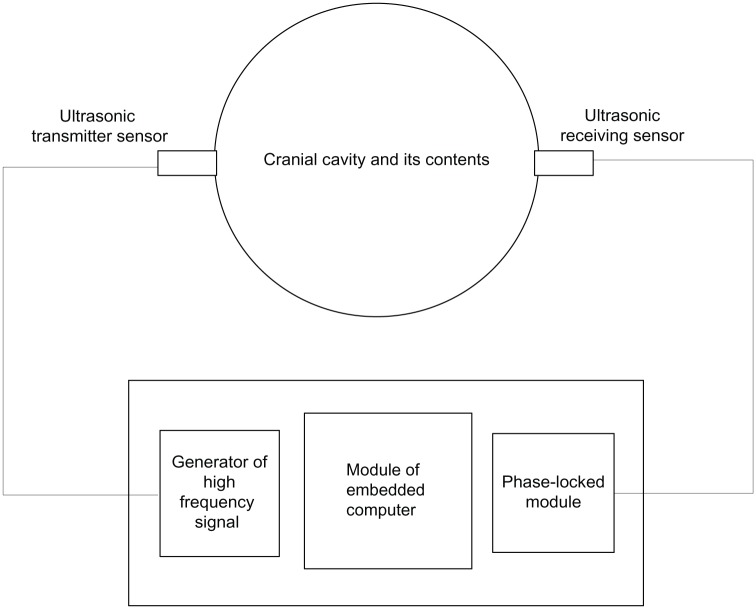
The human cranial cavity can be viewed as a closed container, the interior of which is full of brain tissue and CSF. The cranial cavity has only one passageway that leads to the spine. The cranial cavity and the spine are full of CSF. According to this anatomical structure, we designed a blackbox model to monitor ICP.16 The monitoring instrument is simplified in the sketch shown in Figure 1.
Figure 1.
Schematic of monitoring method.
In Figure 1, the cranial cavity is depicted as a closed container in which uniform stress exists. On each side of the container, left and right, an ultrasonic transducer is placed. On the left is the transmitter, which converts electrical energy into mechanical energy, meaning it can transform electrical signals into ultrasonic waves. On the right is the receiver, which converts mechanical energy into electrical energy, ie, it can transform ultrasonic waves that have passed through brain tissue from the left to the right into electrical signals. The received signal involves information that has been modulated by ICP. Thus, we can compute the value of ICP from the received signal by microcomputer. In addition, the instrument includes two other components: a generator of high-frequency signals and a phase-locked loop. The generator of high-frequency signals can produce and send a high-frequency signal to the transmitting transducer. The task of the phase-locked loop module is to measure phase difference between received and transmitted signals. The embedded computer works out the ICP value according to the phase difference.
Theoretical basis of the instrument
In essence, monitoring ICP by ultrasound is a mechanical process that examines the relationship between propagation characteristics of ultrasound and stress acting on brain tissue. It was believed that wave velocity and phase were only related to inherent properties of the material. In other words, ultrasonic propagation characteristics would not be affected by stress in a specific material. This idea is changing gradually. Since Hughes and Kelly put forward a preliminary theory of acoustoelasticity in solids for the sake of getting third-order elastic modulus of solid by ultrasound in 1953,17 and Tokuoka and Iwashimizu proposed acoustoelastic birefringence effect in 1968,18 more than half a century has passed, and acoustoelastic theory has been developing very quickly. At present, more and more researchers believe that ultrasonic propagation characteristics are influenced by the stress state of the material, ie, ultrasonic parameters change with changes in stress, eg, wave velocity or phase. In recent years, along with advances in ultrasonic testing technology, acoustoelasticity theory has been used more and more widely for measuring the initial stress of solids, such as in the detection of rock stress or welding residual stress.19,20 However, the theory has never been used for detecting the stress of soft matter, eg, organ tissue, in the past. Research on soft matter has been paid more and more attention in recent years, because soft matter is a class of very important material and is widely used. Biological tissues and organs are all soft matter. Many disease-detection methods are finding changes in mechanical properties. Thus, detection of the inner stress of biological tissues or other soft matter has very important practical significance. Pao et al21 and Wu et al22 studied the influence on elastic wave velocity due to plastic deformation. However, nobody has measured the inner stress of soft matter such as biological tissues based on ultrasonic acoustoelastic theory.
The relation between ultrasonic wave motion and stress is called the stress-acoustic effect or acoustoelastic effect.23 This theory is the theoretical foundation of ICP monitoring by ultrasound. Acoustoelasticity theory has four fundamental assumptions:24
assumption of continuous medium
ultrasonic propagation is small perturbation superposed upon static and limited large deformation
the material is superelastic and homogeneous
the deformation of the material could be viewed as an isothermal and isentropic process.
According to the acoustoelastic theory, the state of brain tissue can be divided into three kinds:
natural state – ICP is normal and brain tissue has not been deformed
initial state – pre-deformation state when ICP has increased
final state – testing state when ultrasound is being overlaid.
These three states can be described by using three kinds of coordinate system: natural system of coordinates (ξ), initial system of coordinates (X), and final system of coordinates (χ). Accordingly in accordance with acoustoelasticity theory we can get an acoustoelastic equation for the initial system of coordinates, as shown in equation 1:
| (1) |
Equation 1 is the equation of motion as ultrasound propagating in a medium. Solving it will produce the wave equation, thus the ultrasonic wave velocity or phase difference can be calculated.
In equation 1, CIJKL is equivalent stiffness, and it depends on material constant and initial displacement field, and reflects the intrinsic property of the material. Equivalent stiffness of different materials is not identical, and will not change along with loads, deformation, time, or velocity. Thus, at a certain temperature, stress is determined uniquely by strain field. Equivalent stiffness is symmetrical as shown here:
| (2) |
CIJKL can be calculated by equation 3:
| (3) |
In equation 3, cIJKL (the c is lowercase) can be expressed as equation 4:
| (4) |
The symbol eMN indicates tiny deformation.
| (5) |
All of these formulas adopt the notation of a Cartesian tensor. Respectively , , and mean initial displacement, strain, and stress described in the initial coordinate system; ρi indicates the density in the initial state; cαβγδ is the tensor of second-order elastic constant of a material. For isotropic materials, it has two independent second-order elastic constants, which are called Lamé constants; cαβγδζη means the tensor of third-order elastic constant of a material. There are three third-order elastic constants, which are called Murnaghan constants.
The design of the experimental model
A design principle is that the experimental model must fit with the real environment and actual conditions very closely. We studied prior knowledge of physiology and anatomy of the cranial cavity. The mechanical parameters of brain tissue are shown in Table 1.25
Table 1.
Mechanical parameters of each component in the cranial cavity
| Tissue | Young’s modulus (MPa) | Poisson’s ratio | Density (kg/m3) |
|---|---|---|---|
| Skull | 6000–10000 | 0.200–0.220 | 1210–2150 |
| CSF | 0.012–0.149 | 0.489–0.499 | 1040.3 |
| Brain tissue | 0.067–1.000 | 0.480–0.490 | 1000–1140.3 |
Abbreviation: CSF, cerebrospinal fluid.
According to the known biomechanical parameters of the cranial cavity and its contents, shown in Table 1, polymethyl methacrylate was selected to simulate the skull and hydrogel to simulate the brain tissue in this paper. Polymethyl methacrylate approximates skull in terms of density, Poisson’s ratio, and Young’s modulus. The properties of CSF of are very close to water, because the main ingredient of CSF is water. Hydrogel belongs to soft matter and has been widely used in the medical field as biomaterial, and in medical experiments, and in some other aspects such as artificial tissues now26–29 There are many kinds of hydrogel, and their mechanical properties are closely associated with the water proportion. In this paper, the proportion of water is 80% and the density of hydrogel 1,004 kg/m3. Poisson’s ratio is 0.49, measured by high-precision strain gauge. Therefore, hydrogel and brain tissue are both very similar to incompressible substances (Poisson’s ratio of absolutely incompressible substance is 0.5). Since hydrogel is a soft material, measurement of Young’s modulus is very difficult. Therefore, we first obtained the compression modulus, and then we calculated Young’s modulus by using the compression modulus and Poisson’s ratio. The calculation formula is indicated in equation 6.30
| (6) |
In equation 6, E0 is Young’s modulus, and Es the compression modulus, ν is Poisson’s ratio. Equation 6 is correct within the linear elastic range. Thus, the measurement of the compression modulus must be limited within the linear elastic range. Since the deformation of hydrogel is minimal when compressed, the accuracy of the strain gauge must be high enough. Young’s modulus for the hydrogel was 0.984 MPa, calculated by equation 6. According to these data, it could be seen that the mechanical properties of the hydrogel in the experiment were very close to the actual parameters of brain tissue. Thus, the model designed in this paper can simulate the real environment of the cranial cavity very well.
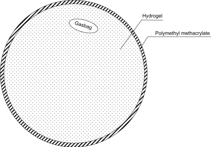
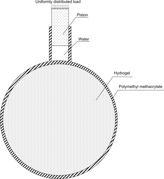
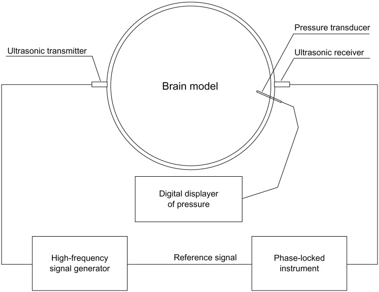
In this paper, we describe two black-box test models and simulate the situation of increased ICP when CSF is increasing or brain tumor respectively. The models are shown in Figures 2 and 3 respectively. The shells of the models were polymethyl methacrylate, which simulates the human skull, and the contents were hydrogel, which simulates the cranial contents. The diameter of the container was 18 cm, and its thickness 2 mm. The model was designed according to the mean value of the human head, and the actual value for each patient would be somewhat different. However, the ultrasonic phase shift is proportional to its flight distance. Thus, the clinical ICP value could be converted proportionally according to the diameter of a specific patient. A sketch of the entire experiment is shown in Figure 4.
Figure 2.
Experiment model 1.
Figure 3.
Experiment model 2.
Figure 4.
Schematic of the model test.
The ultrasonic wavelength is much larger than the size of tiny blood vessels, so the brain tissue could be viewed as a continuous medium when the patient is being monitored by ultrasound. So the first assumption is met.
In preliminary experiments, we determined ultrasonic parameters as follows: frequency 150 kHz, amplitude 1 V (signal voltage adopted as reference unit and definite vibration displacement provided by the sensor parameter), supersonic power limited within 1–10 mW/cm2. Since the hydrogel is incompressible and the deformation very small, the ultrasonic vibration amplitude must be tiny enough to meet the assumed conditions of small perturbation that are claimed in acoustoelastic theory. In the experiments, the ultrasonic amplitude was very tiny and was able to meet the requirement. If the ultrasonic amplitude is too powerful, it will be harmful in terms of biological effect.31 In this model, the ultrasonic power was low enough to avoid damage to the human brain. Furthermore, the energy absorbed by intracranial media was limited to a very low level, so the monitoring process can be deemed an isothermal or isentropic process. Thus, it meets the fourth assumption of acoustoelastic theory.
The actual test objects and equipment are shown in Figure 5. Electrical connection is also shown in Figure 5. The loading speed in the experiment was the same as the speed of human ICP increase.
Figure 5.
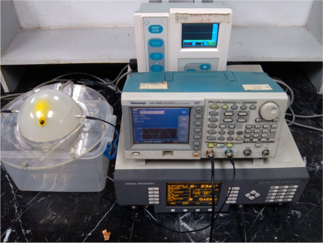
Experiment equipment including a lock-in amplifier, signal generator and stress measuring instrument.
Simulation and experimental results
Equation 1 defines ultrasonic acoustoelasticity when the test object is subject to additional stress. It describes the particle motion in the medium when the stress state has changed. To solve the partial differential equation, it is first necessary to obtain a wave value for ultrasound under initial stress, and then to obtain ultrasonic wave velocity or phase. However, the partial differential equation can be solved analytically within several special status and boundary conditions. In general conditions, the numerical solution of the equation based on finite-element simulation can only be given. In this paper, equation 1 is solved numerically based on finite-element analysis by using Abaqus software (Dassault Systèmes, Vélizy-Villacoublay, France).
Finite-element analysis for the brain experimental model was established and divided into meshes based on the tetrahedron shown in Figure 6. In the finite element software, the element of tet (tetrahedron) was selected. But in fact, some hexahedral was generated automatically in the middle of the model by the software. In the finite-element simulation, an element-stiffness matrix is necessary and is given by equation 5. The matrix shown in equation 5 is a symmetrical matrix. Due to the equivalent stiffness in equation 1 is fourth-order tensor, and two-dimensional matrix can only be inputted into finite-element software. Thus, we adopted the Voigt abbreviation method for the fourth-order tensor in order to transfer it into a two-dimensional matrix and enter it into the software.
Figure 6.
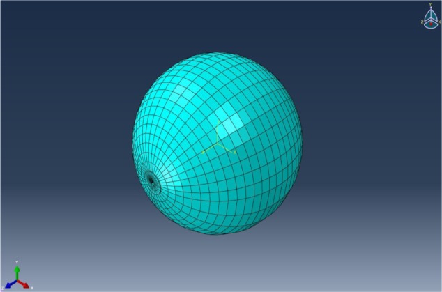
The finite-element model and mesh of the experimental model.
| (7) |
In equation 7, λ, and μ are the second-order elastic constants of the material, known as Lamé constants. These can be acquired by experimental measurement or calculated from the first-order elastic constants, such as Young’s modulus and Poisson’s ratio. The computing formula is shown in equations 8 and 9.
| (8) |
| (9) |
In these two equations, E is Young’s modulus and ν is Poisson’s ratio.
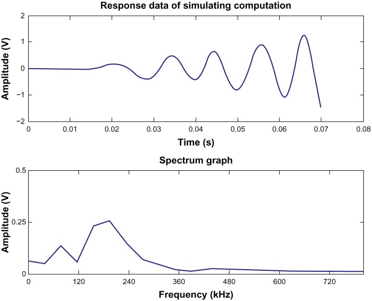
The response curve of the simulation and its spectrum are shown in Figure 7. As an example in Figure 7, the additional load was 0.532 kPa (4 mmHg). The results in Figure 7 show that the theoretical data derived by the finite-element software can meet the actual requirements.
Figure 7.
Response curve of simulation and its spectrum.
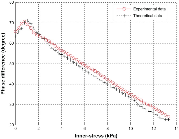
Graphs of both experimental values and calculated values are shown in Figure 8, and the two kinds of values are compared. The curves in Figure 8 are the relationship curves between ultrasonic phase difference and internal stress of the test object. The experimental value is the mean value of the loading process and unloading. The phase difference of theoretical data was calculated by correlation analysis.32
Figure 8.
Relationship between stress and phase difference.
Conclusions
The following conclusions can be drawn from Figure 8. (1) The error between the experimental value and the calculated value based on acoustoelastic theory is no more than 5%. Thus, this kind of ICP-monitoring method has been proved to be correct theoretically. That is to say, the method is feasible in theory and practice, but it needs to be tested clinically for further evaluation. (2) The normal range of adult ICP is 0.7–2.0 KPa (5–15 mmHg). The upper limit of the monitoring instrument for increased ICP is 13.3 kPa (100 mmHg). In the range of 0.7–13.3 kPa, the curve decreases monotonically. Hence, ICP value could be calculated inversely according to the curve from the ultrasonic phase difference acquired by the receiving transducer. (3) The test model meets actual requirements very well. This monitoring method based on ultrasound has the potential to be applied to clinical tests. This method will be verified in clinical testing and the algorithm adjusted appropriately according to testing.
Footnotes
Disclosure
The authors report no conflicts of interest in this work.
References
- 1.Han ZS, Cao MH, Yu PL. Intracranial Pressure and Increased Intracranial Pressure. Gansu: Gansu Science and Technology Press; 1993. [Google Scholar]
- 2.Raboel PH, Bartek J, Jr, Andresen M, Bellander BM, Romner B. Intracranial pressure monitoring: invasive versus non-invasive methods – a review. Crit Care Res Pract. 2012;2012:950393. doi: 10.1155/2012/950393. [DOI] [PMC free article] [PubMed] [Google Scholar]
- 3.Yue XF, Wang L. Monitoring of Intracranial Pressure and New Minimally Invasive Method of Strain Gauge Measurement. Beijing: Science Press; 2008. [Google Scholar]
- 4.Ji Z. The Method and Realization for Noninvasive Measuring of Intracranial Pressure. Beijing: Higher Education Press; 2010. [Google Scholar]
- 5.Li X, Li B, Yang L, et al. Clinical application of invasive intracranial pressure monitoring after severe traumatic brain injury. Jie Fang Jun Yi Xue Za Zhi. 2011;36(12):1323–1325. Chinese [with English abstract] [Google Scholar]
- 6.Wang ZC. Neurosurgery. Wuhan: Hubei Science and Technology Press; 2004. [Google Scholar]
- 7.Zhou NL. Research on the Association among Intraocular Pressure, Intracranial Pressure and Blood Pressure. Hebei: Hebei Medical University; 2011. [Google Scholar]
- 8.Ji Z, Peng CL, Yang L. Instrument realization of non-invasive intracranial pressure measurement based on flash visual evoked potential. Chin J Sci Instrum. 2010;31(12):2809–2814. [Google Scholar]
- 9.Fukushima U, Miyashita K, Okano S, Higuchi S, Takase K, Hagio M. Evaluation of intracranial pressure by transcranial Doppler ultrasonography in dogs with intracranial hypertension. J Vet Med Sci. 2000;32(3):353–355. doi: 10.1292/jvms.62.353. [DOI] [PubMed] [Google Scholar]
- 10.Davids JD, Birch AA, Marchbanks RJ. Non-invasive measurements of intracranial pressure: can coherent averaging show a tilt-dependent change in the measured spontaneous tympanic membrane displacement (stmd) signal in healthy volunteers? J Neurol Neurosurg Psychiatry. 2012;83(3):e1. [Google Scholar]
- 11.Muchnok T, Deitch K, Giraldo P. Can intraocular pressure measurements be used to screen for elevated intracranial pressure in emergency department patients? J Emerg Med. 2012;43(3):532–537. doi: 10.1016/j.jemermed.2010.04.032. [DOI] [PubMed] [Google Scholar]
- 12.Shaw M, Piper I, Campbell P, et al. Investigation of the relationship between transcranial impedance and intracranial pressure. Acta Neurochir Suppl. 2012;114:61–65. doi: 10.1007/978-3-7091-0956-4_11. [DOI] [PubMed] [Google Scholar]
- 13.Yang L, Zhao M, Peng C, Hu X, Feng H, Ji Z. Waveform descriptor for pulse onset detection of intracranial pressure signal. Med Eng Phys. 2012;34(2):179–186. doi: 10.1016/j.medengphy.2011.07.008. [DOI] [PubMed] [Google Scholar]
- 14.Ji Z, Peng CL. Methods and realization for intracranial pressure measurement and analysis. Chin J Sci Instrum. 2012;33(2):457–462. [Google Scholar]
- 15.Rui H, Xu DZ. Research on a new digital automatic ultrasonic inspection system. Chin J Sci Instrum. 2005;26(9):957–960. [Google Scholar]
- 16.Shu H, Zhang YF, Gao L, et al. Research progress on the simulation model for ICP. Space Med Med Eng (Beijing) 2012;25(5):381–385. [Google Scholar]
- 17.Hughes DS, Kelly JL. Second-order elastic deformation of solids. Phys Rev. 1953;92(5):1145–1149. [Google Scholar]
- 18.Tokuoka T, Iwashimizu Y. Acoustical birefringence of ultrasonic waves in deformed isotropic elastic materials. Int J Solids Struct. 1968;(4):383–389. [Google Scholar]
- 19.Tian JY, Hu LL. Progress in theories and experimental technologies of solid acoustoelasticity and its application. Adv Mech. 2010;40(6):652–662. [Google Scholar]
- 20.Zhou XJ, Jiang YJ, Wei Z, et al. Experimental approach to the acoustoelastic method for surface stress testing of aerospace transparency. Chin J Sci Instrum. 2000;21(5):497–500. [Google Scholar]
- 21.Pao YH, Wu TT, Gamer U. Acoustoelastic birefringences in plastically deformed solids. Part I. Theory. J Appl Mech. 1991;58(1):11–17. [Google Scholar]
- 22.Wu TT, Hirao M, Pao YH. Acoustoelastic birefringences in plastically deformed solids. Part II. Experiment. J Appl Mech. 1991;58(1):18–23. [Google Scholar]
- 23.He H. The Development of Ultrasonic Device to Detect Welding Residual Stress. Harbin: Harbin Institute of Technology; 2010. [Google Scholar]
- 24.He LF, Liu J. Technology of Acoustoelasticity. Beijing: Science Press; 2002. [Google Scholar]
- 25.Lu JP. The Restruction[sic] of Brain Finite Modle[sic] and the Analysys[sic] of Little Hammer Striking on the Left Brain Simulation. Tianjin: Tianjin University of Science and Technology; 2006. [Google Scholar]
- 26.Wang T, Jiang XJ. Intelligent hydrogel in in situ myocardial tissue engineer. Adv Cardiovasc Dis. 2008;29(5):683–685. [Google Scholar]
- 27.Li F, Zhou HY, Su YL, Wang CT. Study on the compression properties between articular cartilage and polyvinyl alcohol hydrogel as artificial cartilage. J Med Biomech. 2009;24(6):448–451. [Google Scholar]
- 28.Wang HB, Zhang J, Wang BL. An improved PVA hydrogel as artificial vitreous body and its application on rabbits. J Biomed Eng. 1993;10(1):13–17. [Google Scholar]
- 29.Liu JL, Zhang DK, Ge SR. Preparation and mechanical properties analysis of porous biological ceramics and PVA hydrogel composite material. J Med Biomech. 2011;26(4):341–348. [Google Scholar]
- 30.Gao DZ. Soil Science and Soil Mechanics. 3rd ed. Beijing: China Communications Press; 2001. [Google Scholar]
- 31.Bai J. Ultrasonic Imaging Mechanism in Medicine. Beijing: Tsinghua University Press; 1998. [Google Scholar]
- 32.Mao J, Jiang CH. Phase difference measurement based on correlation analysis. Ship Electron Eng. 2009;29(12):90–92. [Google Scholar]


