Abstract
In this paper, we propose a novel approach for intensity based atlas construction from a population of anatomical images, that estimates not only a template representative image but also a common optimal parameterization of the anatomical variations evident in the population. First, we introduce a discrete parameterization of large diffeomorphic deformations based on a finite set of control points, so that deformations are characterized by a low dimensional geometric descriptor. Second, we optimally estimate the position of the control points in the template image domain. As a consequence, control points move to where they are needed most to capture the geometric variability evident in the population. Third, the optimal number of control points is estimated by using a log −L1 sparsity penalty. The estimation of the template image, the template-to-subject mappings and their optimal parameterization is done via a single gradient descent optimization, and at the same computational cost as independent template-to-subject registrations. We present results that show that the anatomical variability of the population can be encoded efficiently with these compact and adapted geometric descriptors.
1 Introduction
Fundamental to Computational Anatomy is the estimation of the template and the template-to-subject mappings that characterize anatomical variability in a population. For statistical analysis of a set of images it is crucial to efficiently parametrize the anatomical variability. One approach consists of extracting features of the mappings, like the Jacobian matrix of the deformation [3], or its determinant [9]. More comprehensive approaches rely on the statistical analysis of the displacement fields of the voxels grid by using a log-Euclidean technique [2], or on the Riemanian characterization of the group of diffeomorphisms parametrized via the continuous initial momenta map in the LDDMM setting [14].
The intrinsic problem with such approaches is that the fundamental anatomical variability is parametrized in an infinite dimensional space (practically on the order the size of the imaging modality), which does not reflect the intrinsic dimensionality of the anatomical variations in a finite database of images. Indeed, the estimated deformations are usually constrained to be spatially smooth, thus preventing every voxel from moving independently. Moreover, the need for deformation is not equally distributed over the domain, since intensity-based registrations are mostly driven by the level sets of the template image. As a consequence, we hypothesize that the anatomical variability can be characterized by a compact geometric parametrization of much smaller dimension. It has already been shown in [7] that smooth vector fields parameterizing diffeomorphisms can be efficiently approximated by a small number of momenta via a “matching pursuit” technique, where momenta stands for vectors attached to control points.
In this paper we propose a control point parameterization of large deformation diffeomorphisms following [10] to drive template-to-subject image registrations. This differs from LDDMM image registration, for which the deformation is parameterized by a continuous map of momenta that are always parallel to the image gradient [12]. Here, we propose to use a finite set of momenta, which are not constrained in their direction. Control points techniques have been widely used for small deformation transformations [8], its use for large deformation matching of images is challenging. In [13], diffeomorphisms were built by a composition of small B-splines transforms without a comprehensive variational formulation. In [1], diffeomorphisms were characterized via a finite set of initial momenta located at the vertices of a “texture mesh”, but no attempt was made to estimate an optimal mesh describing a whole population of images. The inherent difficulty is to find an efficient way to transport information back and forth from source to target. Indeed, control points flow from source to target (via the deformation φ), whereas the variability in the population is in the target image domain and hence needs to be pulled back to the source to build the template (Isrc ∘φ−1). We solve this issue via a new formulation of the dynamical system which drives the LDDMM registration, borrowed from optimal control theory. It enables us to easily transport points and vectors via simple integration of ODE. One of the striking results of this formulation is that the optimal positions of the control points in the template space can be found at no additional computational cost. We demonstrate that the control points are naturally attracted by the contours of the template image, and a regularity term optimizes their spatial distribution to avoid redundancy in the parameterization. The number of control points determines the number of degrees of freedom of the deformations and therefore the accuracy of the template-to-subject deformations and the sharpness of the atlas. To optimize the number of control points for a given atlas sharpness, we use a log L1-penalty term on the set of initial momenta, in the spirit of the in vogue sparse statistical methods. Our results show that this prior enables to prune the set of control points without sacrificing the description of the anatomical variability. This sparse and adapted parameterization of the variability seems therefore adapted to the statistical analysis of a collection of images.
We follow the now well established paradigm for atlas estimation by first defining pairwise image matching and then using it for population analysis.
2 Image Matching with Discrete Parameterization of Deformations
Image matching term
Let Isrc and Itar two images to be matched and φ a diffeomorphism of the image domain. The source image is deformed into I1 via Isrc ∘ φ−1. Let y = (y1, …, yM) be the concatenation of the location of the voxels in the target image. The deformed image I1 linearly interpolates the gray levels of the neighboring voxels around positions φ−1(yk). We denote y(0) = φ−1(y).
The deformation estimation is driven by the L2 norm between the images:
| (1) |
which depends only on the positions y(0), since the target voxel positions y are fixed on a regular lattice.
Non-linear diffeomorphic deformations
A standard way to construct nonlinear diffeomorphisms is to integrate infinitesimal transformation parametrized via a time-varying vector field vt(x) over the time interval [0, 1]: φ̇t(x) = vt(φt(x)), with initial condition φ0(x) = x. Under the conditions detailed in [4] and satisfied here, the resulting (φt)t∈[0,1] is a flow of diffeomorphisms (for each time t ∈ [0, 1], φt is a diffeomorphic deformation).
Let c0 = {c1, …, cN} be a finite set of control points. These points move in space according to the deformation: ci(t) = φt(ci). By analogy with landmark matching [10], we parametrize the instantaneous velocity field vt(x) by a set of time-varying vectors α(t) = {α1(t), …, αN(t)} as:
| (2) |
where K is an interpolating kernel, assumed hence forth without loss of generality, to be Gaussian: K(x, y) = exp(−|x - y|2)/σ2).
The positions of the control points ci(t) depend on the velocities and therefore on the vectors α(t). They satisfy a set of N coupled ODEs: , with initial condition at t = 0: ci(0) = ci. In a matrix form, this can be written as: ċ(t) = f(c(t), α(t)) with c(0) = c0.
Once these positions have been estimated, the motion of any point x0 is computed by solving the ODE: ẋ(t) = vt(x), x(0) = x0. It follows that the flow of diffeomorphisms is entirely determined by the time-varying vectors α(t) and the initial control points c0.
In particular, the points in the data term are computed by flowing the positions yk from t = 1 (target space) back to time t = 0 (source space): one integrates backward the ODE: with the final condition yk(1) = yk. This equation in matrix form becomes ẏ = g(y(t), c(t), α(t)), y(1) = y. The solution at time t = 0 is .
One defines the regularity of the deformation as its total kinetic energy: , using the Sobolev norm of the velocity field associated with the kernel K. We write it as .
Criterion minimization
Now, the matching criterion can be written as:
| (3) |
subject that:
| (4) |
where γ is the scalar trade-off between the regularity of the deformation and the fidelity to data. The minimization of this criterion with respect to the time-varying vectors α(t) leads to the source-to-target deformation parameterized by the control points c0. The minimization with respect to the c0 leads to the optimal positions of the control points which parameterize the best matching possible. Both optimizations will be done via a single gradient descent.
It has been shown that the regularity term for γ > 0 ensures that the flow of diffeomorphisms builds a geodesic path in a certain group of diffeomorphisms [4]. This means that at the minimum the flow of diffeomorphisms is entirely determined by the initial momenta at time t = 0: (c0, α(0)).
We optimize the criterion via a gradient descent. The initial conditions are α(t) = 0 for all t (which gives φt(x) = x, i.e. no deformation) and the control points c0 are given on a regular lattice. A variation of the momenta δα(t) and of the control points initial position δc0 induces a variation of the whole path of the control points δc(t) from source (t = 0) to target (t = 1). Then, this changes the path of the target voxels flowing back to the source: it leads to a variation of the positions δy(0) and hence a variation of the criterion. We show in Appendix A, that the gradient of the criterion with respect to these two variables is:
| (5) |
where ηc and η̃y are 3N dimensional vectors, which satisfy one forward and one backward integral equations:
and η̃y is the solution of the set of N linear equations for all t:
| (6) |
The auxiliary variable ηy is computed forward in time: it transports the usual image force ∇yk(0)A from the source (t = 0) to the target space (t = 1). Once at time t = 1, this variable is used as a source term in the ODE satisfied by the variable ηc, which is integrated backward in time. At time t = 0, this variable is used to update the position of the control points in the source image domain, at no additional cost. The overall gradient descent is summarized in Algorithm 1.
Algorithm 1.
Image Matching with finite-dimensional parameterization
| 1: | αi(t) ← 0 for all i = 1, …, N and all t |
| 2: | c0 ← initial positions of control points (input) |
| 3: | repeat {Gradient descent} |
| 4: | {Compute path of control points (forward integration)} |
| 5: | |
| 6: | {Compute deformed source image (backward integration)} |
| 7: | |
| 8: | {Compute gradient of source image} |
| 9: | ∇yk(0)E = 2 (I0(yk(0)) - I1(yk)) ∇yk(0)I0 |
| 10: | {Compute auxiliary variable ηy(forward integration)} |
| 11: | |
| 12: | {Compute auxiliary variable ηc (backward integration)} |
| 13: | |
| 14: | {Solve the linear system} |
| 15: | (η̃y is of dimension 3N) |
| 16: | {Compute gradient} |
| 17: | |
| 18: | {Update time-varying momenta} |
| 19: | αi(t) ← αI(t) − ε∇αiJ(t) |
| 20: | {Update initial positions of control points} |
| 21: | |
| 22: | until Convergence |
Remark 1 (Interpretation in the small deformation setting)
To better understand these equations, we linearize this model in time. Then, the flow of diffeomorphisms is reduced to the transform: φ(x) = x + v(x) parameterized by the fixed momenta (c0, α(0)). For small deformations, the inverse is approximated by φ−1(yk) = yk - v(yk). The matching criterion becomes:
| (7) |
whose gradient can be computed straightforwardly as:
This is exactly the linearization of the gradient (5), at order 0 for the first equation and at order 1 for the second one (the zeroth order vanishing).
The first equation consists of two terms: the first one is the convolution of the usual image force at the control points, the second one is a regularizer of the estimated momenta, which can be seen as a low-pass filter on the momenta. The second equation is the update rule for the control points positions. The first term shows that they are attracted by the voxels where the gradient of the image is large (i.e. the contours), provided that the momenta αi pushes in the ‘right’ direction, that of the image force (making the dot product positive). The second term is a repulsion term which moves away two control points which carry momenta pointing in the same direction, thus limiting the redundancy of the parameterization at the scale of the kernel σ.
3 Atlas Estimation with Common Sparse Parameterization of Deformations
3.1 Joint Optimization of the Template Image and the Deformations
Given a set of Ns images, one wants to find a template image I0, the optimal set of control points c0 in the image domain and the optimal set of Ns time-varying vectors αs(t), which drive the registration of the template to every image. As a consequence, the criterion to be minimized is given by:
| (8) |
subject that:
| (9) |
where we notice that the initial and final condition of the ODEs are shared among the population. This criterion has the same form as in (3). Denoting Es each term of the sum, the gradient with respect to c0 and the αs(t) is given as:
| (10) |
This means that the weighting vectors are computed for Ns parallel registrations by integrating the ODEs of (5). After the back and forth integrations, the auxiliary variables are averaged over the subjects to update the common parameterization of the deformations c0.
The gradient with respect to the template image I0 is the sum of the gradient ∇I0
As (ys(0)). The value I0(yk(0)) is computed as Σp∈
 (yk(0))
ρp(yk(0))I0(πp(yk (0))), where
 (y) denotes the set of 8 neighboring voxels πp(y) of the position y and ρp(y) the weights corresponding to the trilinear interpolation. Let Rs be the residual image I0(y(0)) - Is. Then a variation δI0 of the template image leads to:
where one multiplies the gray levels for each voxel in the source domain instead of the target domain. This shows that the gradient of A is the partial volume projection [6] of the residual image. This is computed by flowing the voxel yk back in the source domain and distributing its gray level at the 8 neighboring voxels with the same weight as for a trilinear interpolation. The accumulation of such values for every voxel and every subject gives the gradient.
3.2 Sparsity Enforced by log −L1 Penalty Term
The number of control points determines the number of degrees of freedom of the deformations. The more control points, the more accurate the registrations, the sharper the template image. Consequently, the optimization of the previous criterion tends to use as many control points as possible. However, as we will see in our experiments, from a certain point, adding more momenta only marginally increase the atlas sharpness at the cost of adding much more noise in the description of the variability. To find the optimal number of degrees of freedom for an accurate description of the variability, we use a numerically stabilized log −L1 penalty motivated by [5]:
| (11) |
where N denotes the total number of control points, the ith initial momentum vector of the sth subject. For numerical stability we truncate the log function near 0 via: logc(x) = max(log(x), log(c))-log(c) a positive penalty. This penalty function has almost no effect on large momenta, whereas it enforces the small momenta to converge to zero. The constant c is a threshold to avoid numerical instability, set typically at the voxel size. Every 5 iterations of the gradient descent, control points with an initial momenta smaller than c are pruned.
This penalty induces only a small change in the algorithm. The quantity is added to each ∇αiEs as soon as .
4 Experiments
Our method is independent of the dimension of the images. In this section, we focus on 2D images for a better visualization and understanding of the results.
In Fig. 1, we show the matching of two synthetic 2D images of size 256×256. It shows that a discrete parameterization (with the maximum number of degrees of freedom: one control point every σ) enables a perfect matching, as would do a parameterization by a continuous momenta map as in [4]. Using much fewer momenta, the matching is less accurate. But, moving the control points at their optimal position near the contours drastically increases the matching accuracy.
Fig. 1.
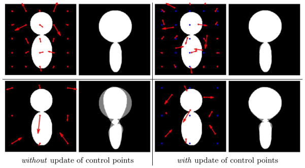
Synthetic image matching with 25 (top) and 9 (bottom) control points. On the left of each panel: the source image with the initial momenta (red arrows). On the right the superimposition of the deformed source and target image. First row shows that a discrete parameterization is sufficient for a perfect matching. Second row shows that moving the control points to their optimal positions gives a much better representation of the shape differences for a fixed number of parameters. σ = 50 voxels, γ = 10−2.
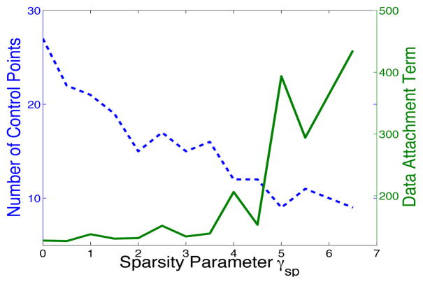
In Fig. 2, we construct an atlas from 3 synthetic images. The sparsity prior enables to select the most important momenta and to give a compact representation of the shape variability. Fig. 3 shows that the initial number of control points can be divided by 5 without sacrificing much of the atlas sharpness.
Fig. 2.
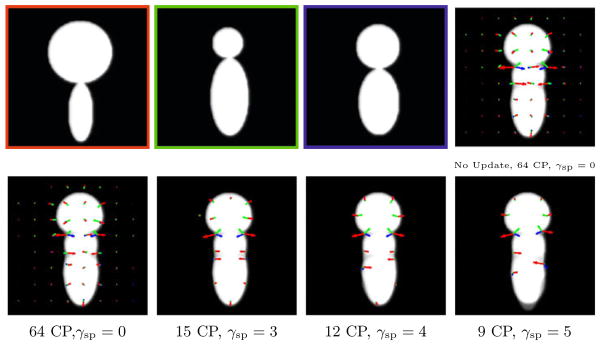
Atlas from 3 images (top left). Template and initial momenta shown without (top right, A = 163) and with (bottom left, A = 127) update of control points. The sparsity term drastically reduces the number of control points, for a comparable atlas sharpness: data term A = 134 and 206 for γsp = 3 and 4. For γsp = 5, the atlas sharpness worsens (A = 393), as noticeable at the bottom of the image. γ = 0.1, σ = 30 voxels.
Fig. 3.
Graph of the the number of control points and the fidelity-to-data term with respect to the sparsity parameter γsp with data of Fig. 2. There is a whole range γsp ∈]0, 4] for which the number of control points can be divided by 2.4 to 5.3 (from 27 to 12 compared to the initial 64 control points) for an almost constant atlas sharpness.
In Fig. 4, we show the motion of the control points to the contours of the source image during a registration between MRI slices of size 176 × 256. In Fig. 5, we construct an atlas from 5 of such images. The sparsity prior shows that the main variations in the population are located at the skull, near the ventricles and the main sulci, like the frontal sulcus. These structures are indeed the most salient and variable at the scale of analysis: σ = 5 voxels.
Fig. 4.
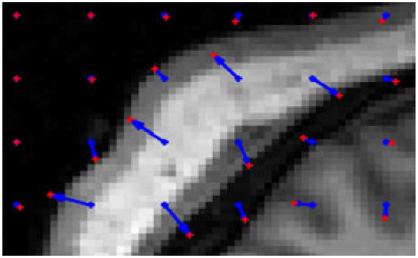
Registration of brain MRI slices: close-up on the left posterior area of the source image. Initial control points in blue moved to the positions shown in red. They moved toward the contours of the image. They do not move in absence of image force in homogeneous areas. σ = 5 voxels and γ = 10−3.
Fig. 5.
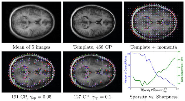
Atlas from 5 brain images. Top row: estimated atlas with update of control points but without sparsity enforced. Bottom row: with enforced sparsity, the control points focus on the skull, the ventricles and the major sulci. The graph shows that we can achieve an equivalent description of the variability with 40.8% to 27.1% of the original 468 momenta, for γsp ∈]0, 0.1]. σ = 5, γ = 5 10−3.
5 Discussion and Conclusion
In this paper, we present a new method for parameterizing large and dense image deformations via a discrete set of control points. Given a set of images, we estimate the template image, the template-to-subject deformations and their parameterization via the optimal placement of the control points and the optimal number of them according to a sparse prior. The whole estimation is posed as a single optimization problem and is solved by a single gradient descent. This is more controllable and more efficient than usual alternated minimizations. The algorithm requires only a solution of ODEs and linear systems; no heuristic rule is used to update the control points. By contrast, a death/birth procedure of control points could have been investigated, but at the cost of more heuristic and arbitrary priors. Our results show that the anatomical variability can be efficiently described by small number of well-placed momenta. We expect to show in the future that these new parameterizations substantially improve the statistical analysis of sets of 3D anatomical images. Future work will extend this framework to include the construction of geodesic diffeomorphisms by integration of Hamiltonian systems, as initiated in [1,11] Future work will also focus on the automatic estimation of the best trade-offs between atlas sharpness, sparsity and regularity of the deformations by adding priors on γ and γsp.
Acknowledgments
This work was supported by NIH grants: NIBIB (5R01 EB007 688), NCRRR (P41 RR023953), ACE-IBIS (RO1 HD055741), and NA-MIC (U54 EB005149).
A Differentiation of the Criterion
A variation of the momenta δα(t) and the initial position of the control points δc0 induces a variation of the path of the control points δc(t) and then of the voxel positions δy(t). This induces the variation of the criterion:
| (12) |
The variations δc(t) and δy(t) satisfy the linearized ODEs:
with δc(0) = δc0 and δy(1) = 0. Let and . The solution of these linear ODEs with source terms are:
Plugging these equations into (12) and using Fubini’s theorem leads to:
Therefore the gradient of E with respect to the L2 metric is given as:
| (13) |
where we have denoted:
| (14) |
Since and , we have:
| (15) |
Given the definitions of f,g and L, the L2-gradient can be written as:
| (16) |
where k(y, c) denotes the 3M -by 3N block matrix whose (i, j)th-block is K(yi, cj).
The Sobolev gradient associated to the metric k(c(t), c(t)) is therefore:
| (17) |
which requires to solve a linear system. If control points gets closer than σ, then the matrix k(c(t), c(t)) is badly conditioned [6]. In this case, we adjust σ in this matrix to the minimal distance between control points and use the gradient kadj (c(t), c(t))−1 ∇L2E, which interpolates between the L2 gradient (σadj → 0) and the Sobolev gradient (σadj → σ).
References
- 1.Allassonnière S, Trouvé A, Younes L. Geodesic shooting and diffeomorphic matching via textured meshes. In: Rangarajan A, Vemuri BC, Yuille AL, editors. EMMCVPR 2005. LNCS. Vol. 3757. Springer; Heidelberg: 2005. pp. 365–381. [Google Scholar]
- 2.Arsigny V, Commowick O, Pennec X, Ayache N. A log-euclidean framework for statistics on diffeomorphisms. In: Larsen R, Nielsen M, Sporring J, editors. MICCAI 2006. LNCS. Vol. 4190. Springer; Heidelberg: 2006. pp. 924–931. [DOI] [PubMed] [Google Scholar]
- 3.Ashburner J, Hutton C, Frackowiak R, Johnsrude I, Price C, Friston K. Identifying global anatomical differences: deformation-based morphometry. Human Brain Mapping. 1998;6(5–6):348–357. doi: 10.1002/(SICI)1097-0193(1998)6:5/6<348::AID-HBM4>3.0.CO;2-P. [DOI] [PMC free article] [PubMed] [Google Scholar]
- 4.Beg MF, Miller MI, Trouvé A, Younes L. Computing large deformation metric mappings via geodesic flows of diffeomorphisms. IJCV. 2005;61:139–157. [Google Scholar]
- 5.Candès EJ, Wakin MB, Boyd SP. Enhancing sparsity by reweighted L1 minimization. Journal of Fourier Analysis and Applications. 2008;14(5):877–905. [Google Scholar]
- 6.Durrleman S. Thèse de sciences (phd thesis) Université de Nice-Sophia Antipolis; Mar, 2010. Statistical models of currents for measuring the variability of anatomical curves, surfaces and their evolution. [Google Scholar]
- 7.Durrleman S, Pennec X, Trouvé A, Ayache N. Statistical models of sets of curves and surfaces based on currents. Med Im Anal. 2009;13(5):793–808. doi: 10.1016/j.media.2009.07.007. [DOI] [PubMed] [Google Scholar]
- 8.Glasbey CA, Mardia KV. A penalised likelihood approach to image warping. Journal of the Royal Statistical Society, Series B. 2001;63:465–492. [Google Scholar]
- 9.Gogtay N, Lu A, Leow AD, Klunder AD, Lee AD, Chavez A, Greenstein D, Giedd JN, Toga AW, Rapoport JL, Thompson PM. 3D growth pattern abnormalities visualized in childhood-onset schizophrenia using tensor-based morphometry. Proc Natl Acad Sci. 2008;105(41):15979–15984. doi: 10.1073/pnas.0806485105. [DOI] [PMC free article] [PubMed] [Google Scholar]
- 10.Joshi S, Miller M. Landmark matching via large deformation diffeomorphisms. IEEE Transaction on Image Processing. 2000;9(8):1357–1370. doi: 10.1109/83.855431. [DOI] [PubMed] [Google Scholar]
- 11.Marsland S, McLachlan R. A hamiltonian particle method for diffeomorphic image registration. In: Karssemeijer N, Lelieveldt B, editors. IPMI 2007. LNCS. Vol. 4584. Springer; Heidelberg: 2007. pp. 396–407. [DOI] [PubMed] [Google Scholar]
- 12.Miller M, Trouvé A, Younes L. Geodesic shooting for computational anatomy. Journal of Mathematical Imaging and Vision. 2006;24(2):209–228. doi: 10.1007/s10851-005-3624-0. [DOI] [PMC free article] [PubMed] [Google Scholar]
- 13.Rueckert D, Aljabar P, Heckemann RA, Hajnal JV, Hammers A. Diffeomorphic Registration Using B-Splines. In: Larsen R, Nielsen M, Sporring J, editors. MICCAI 2006. LNCS. Vol. 4191. Springer; Heidelberg: 2006. pp. 702–709. [DOI] [PubMed] [Google Scholar]
- 14.Singh N, Fletcher P, Preston J, Ha L, King R, Marron J, Wiener M, Joshi S. Multivariate statistical analysis of deformation momenta relating anatomical shape to neuropsychological measures. In: Jiang T, Navab N, Pluim JPW, Viergever MA, editors. MICCAI 2010. LNCS. Vol. 6363. Springer; Heidelberg: 2010. pp. 529–537. [DOI] [PubMed] [Google Scholar]


