Abstract
Subtle changes in knee kinematics may substantially alter cartilage contact patterns and moment generating capacities of soft tissues. The objective of this study was to use dynamic magnetic resonance imaging (MRI) to measure the influence of the timing of quadriceps loading on in vivo tibiofemoral and patellofemoral kinematics. We tested the hypothesis that load-dependent changes in knee kinematics would alter both the finite helical axis of the tibiofemoral joint and the moment arm of the patellar tendon. Eight healthy young adults were positioned supine in a MRI-compatible device that could impose either elastic or inertial loads on the lower leg in response to cyclic knee flexion-extension. The elastic loading condition induced concentric quadriceps contractions with knee extension, while an inertial loading condition induced eccentric quadriceps contractions with knee flexion. Peak internal knee extension moments ranged from 23–33 Nm, which is comparable to loadings seen in normal walking. We found that anterior tibia translation, superior patella glide, and anterior patella translation were reduced by an average of 5.1 mm, 5.8 mm and 2.9 mm when quadriceps loading coincided with knee flexion rather than knee extension. These kinematic variations induced a distal shift in the finite helical axis of the tibiofemoral joint and a reduction in the patellar tendon moment arm. We conclude that it may be important to consider such load-dependent changes in knee kinematics when using models to ascertain soft tissue and cartilage loading during functional tasks such as gait.
Keywords: Cine-phase contrast imaging, musculoskeletal models, eccentric contraction, finite helical axis, patellar tendon, moment arm
Introduction
Subtle changes in secondary knee kinematics can substantially alter cartilage contact loading during gait, and thereby potentially contribute to the pathomechanics of osteoarthritis (Andriacchi et al., 2004; Chaudhari et al., 2008). To investigate such links, gait models are often used to estimate muscle forces, which are then applied in a computational knee model to predict the distribution of joint contact loads (Kim et al., 2009; Shelburne et al., 2006). However, gait models typically use a simplified knee model with pre-defined constraints on secondary motion (Collins and O’Connor, 1991; Sasaki and Neptune, 2010). For example, the knee has often been modeled as kinematic joint in which tibiofemoral translations and non-sagittal rotations are constrained functions of knee flexion (Arnold et al., 2010; Wilson and O’Connor, 1997). These functions are often based on the passive behavior of cadaveric knees in which the 3D motion is determined by the ligamentous constraints and geometry of the articular surfaces (Walker et al., 1988; Wilson et al., 2000). However, it is recognized that knee kinematics are dependent on loading and thus not strict functions of knee flexion (Blankevoort et al., 1988). For example, at a given knee flexion angle, external tibia rotation and anterior tibia translation during gait can differ markedly between the stance and swing phases of gait (Dyrby and Andriacchi, 2004; Lafortune et al., 1992), presumably due to differences in the ground reaction force and soft tissue loads. Such effects may be important to consider in gait models, since secondary kinematic changes have the potential to alter the lines of action and moment arms of muscles and hence the cartilage loading seen at the joint.
Advances in dynamic magnetic resonance imaging (MRI) have been used to accurately measure three-dimensional in vivo tibiofemoral and patellofemoral kinematics (Barrance et al., 2007; Seisler and Sheehan, 2007; Sheehan et al., 1998, 1999). Such data have been used to track the finite helical axis of the tibiofemoral joint and moment arm of the patellar tendon (Sheehan, 2007b, c). However, to date, in vivo tibiofemoral kinematics have primarily been measured with MRI under no- or low-load conditions. We recently introduced a MR compatible loading device which is compatible with closed bore magnets and can be used to vary the timing of muscle loading in a knee flexion-extension motion cycle (Silder et al., 2009). The objective of this study was to investigate the influence of the timing of quadriceps loading on in vivo tibiofemoral and patellofemoral kinematic patterns. We expected that eccentric quadriceps loading with knee flexion would induce an anterior shift of the tibia and superior translation of the patella. We further hypothesized that load-dependent variations in in vivo kinematics would alter both the finite helical axis of the tibiofemoral joint and the moment arm of the patellar tendon. Support for this hypothesis would raise questions about the validity of using a kinematically constrained knee model in which functional joint rotation axes and moment arms are assumed to be independent of load.
Methods
Eight subjects (4 females, 4 males, age, 24±2.2y; height, 1.73±0.10m; mass, 70±12kg) participated after giving informed consent according to a protocol approved by the University of Wisconsin’s Health Sciences Institutional Review Board. The right knee of each subject was tested in two separate sessions. The first session took place in a motion analysis laboratory and was used to assess the repeatability of cyclic knee motion, loading and induced quadriceps activities. The second session took place in the University of Wisconsin Hospital and Clinics and involved the collection of dynamic MR images during cyclic knee flexion-extension.
Loading Device
We constructed a MRI compatible device that allowed subjects to flex and extend their knee against either elastic or inertial loads within the bore of a MR scanner (Silder et al., 2009). Each subject was positioned supine on the device, such that their right knee rested on a padded support assembly and was aligned with the axis of a rotating brace. The lower leg was securely strapped to the brace, which was coupled via a flat belt to a loading assembly (Fig. 1). Gearing in the loading assembly was used to generate 13.3° of loading shaft rotation for every 1° of knee flexion. Subjects were asked to flex and extend their knee cyclically in synchronization with a metronome rate of 30 cycles per minute (f=0.5Hz). Elastic loading trials were performed with a stainless steel torsion spring (k=0.3Nm/rad) mounted on the loading shaft. Inertial loading trials were performed with a set of high-density disks (I=348kg-cm2) mounted on the shaft. Assuming that the motion is harmonic, it can be shown that the elastic and inertial loading conditions induce peak internal knee extension moments at max knee extension and flexion, respectively (Appendix A).
Figure 1.
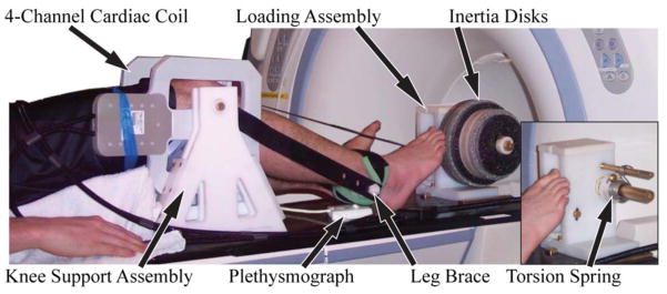
Subjects performed cyclic knee flexion-extension tasks on a MRI compatible loading device. The leg brace was secured to the lower leg and coupled to a loading assembly that imposed either elastic (torsion spring) or inertial loads (via rotating inertia disks) on the quadriceps. Imaging was performed using a 4 channel cardiac coil positioned on either side of the knee. A plethysmograph placed below the foot was used to gate the cine-PC imaging sequence.
Motion Analysis
Each subject first performed the flexion/extension task in a motion analysis lab while limb kinematics, EMG signals and applied forces were simultaneously collected. Each subject performed 3 repeat trials under both the elastic and inertia loading condition, with the order of loading randomized. A single trial lasted two minutes and a minimum of 2 minutes rest was provided between trials. A 60cm diameter cylinder was placed around the lower leg to emulate the range of motion restricted in a scanner. An active motion capture system (PhoeniX Technologies Incorporated, Burnaby, British Columbia) was used to record the 3D positions of two markers placed on the leg brace during the trials. Two tensile load cells (FT24, Measurement Specialties, Hampton, Virginia) were used to monitor the tension in the top and bottom loop of the flat belt. Surface electrodes (Delsys 2.1 single differential electrodes, Boston, Massachusetts) were used to monitor EMG activities of the vastus medialis, vastus lateralis, rectus femoris, lateral hamstrings, and medial hamstrings. EMG and load cell signals were collected at 1000Hz using a 12 bit A/D system (National Instruments, Austin, Texas), while kinematic data were collected synchronously at 100Hz.
Marker kinematics were bi-directionally low-pass filtered with a 3rd order low-pass (6Hz) Butterworth filter and used to compute the knee flexion angle (θk throughout each trial. Knee angles were numerically differentiated to estimate the knee angular velocity and acceleration (θ̈k). Kinematic and force data were then used in an inverse dynamics analysis of the leg to compute the net internal knee flexion moment (Eq. 1):
| (1) |
where rp (=.0635 m) is the leg brace pulley radius; Ft and Fb are the measured top and bottom belt tensions; ml is the estimated mass of the subject’s lower leg and foot; ℓ is the distance from the knee joint to the lower leg center of mass; and θt is the fixed thigh angle relative to horizontal. Repeatability was assessed by evaluating variability in the cycle time period, the maximum and minimum knee flexion angle, the peak knee extension moment, and the angle at which the peak moment occurred.
The raw EMG signals were band-pass filtered at 20–450Hz, full-wave rectified and then low pass filtered at 6Hz; all with bi-directional 3rd order Butterworth filters. For each trial, we then computed the average rectified EMG activity over four phases of the flexion-extension cycle: e2 – mid knee flexion to peak knee extension, f1 – peak knee extension to mid knee flexion, f2 – mid knee flexion to peak flexion, e1 – peak flexion to mid knee flexion. Activity magnitudes were then averaged across all cycles for each loading condition. Paired t-tests were used to assess the effect of load on mean peak knee extension moment, the angle of peak moment and the average EMG activities during the four phases of the motion cycle.
MRI Image Collection
For the imaging trials, the device was placed on the couch of a 1.5T MRI scanner (HDx, v15.0, GE Healthcare, Waukesha, Wisconsin). The subject was positioned supine on the device with the right knee aligned with the leg brace axis, and a four channel cardiac coil positioned about the knee (Fig. 1). A plethysmograph placed on the base and pointing at the posterior of the subject’s foot was used to gate the cine image acquisitions. The cyclic flexion-extension rate was maintained by having the subjects track a metronome beat transmitted via headphones.
For each loading condition, we first collected a gated cine spoiled gradient echo (“fastcard”) scan (field of view = 24 cm, slice thickness=8mm, TR=5.1ms, TE=1.4ms, 256×160 matrix, segmentation factor = 12, receiver bandwidth = ±32kHz, flip angle = 15°, total scan time =32 sec) of an axial imaging plane located at the mid-patella. Twenty images were reconstructed throughout the flexion/extension cycle. These data were then used to define a sagittal-oblique imaging plane that was perpendicular to the posterior edges of the femoral condyles, bisected the mid-patella, and was medial to the popliteal artery (Seisler and Sheehan, 2007). A second fastcard scan was acquired using this sagittal-oblique plane. For each loading condition, we then performed a series of fastcard and cine phase-contrast (cine-PC) image collections. Fastcard acquisitions were obtained using transverse cross-sections that bisected the: a) mid-patella at full extension, b) tibia near the insertion of the patellar tendon onto the tibia at full extension, c) femur ~2cm superior of the most inferior point of the femoral notch. Three repeat cine-PC scans (field of view = 24 × 16cm, slice thickness=8mm, TR=12.0ms, TE=5.2ms, 256×160 matrix, 20° flip angle, segmentation factor = 2, receiver bandwidth =±19kHz, VENC=200mm/s, scan time = 1:48 minutes) were then obtained using the sagittal-oblique imaging plane. Cine-PC imaging was used to measure pixel velocities in 3 perpendicular directions throughout the motion, which were later integrated to compute the three-dimensional joint motion. A minimum of two minutes rest was provided between trials.
Tracking Segment Motion
Reference frames were established in the femur, tibia and patella segments using images of the knee in the most extended posture (Fig. 2). Axial fastcard images were used to define a mediolateral axis, while cine-PC images were used to define the segment longitudinal axis. The subsequent translation and orientation of the segments were determined via analysis of the cine-PC velocity data set (Fig. 3). Tracking was accomplished by first identifying regions of interest (ROI) within each segment. For each frame, we computed the translational and angular velocities that best agreed with the pixel velocities of each ROI (see Appendix B for details). Trapezoidal integration of the velocities was performed to compute the translational and rotational positions throughout the flexion-extension cycle. Integrations were performed both in forward and backward directions, and a weighted average of these results produced cyclic 6 degree-of-freedom (DOF) kinematic trajectories for each joint. Fourier integration was then used to refine segment kinematic trajectories, a process which optimally incorporated higher frequency information into the integration (Zhu et al., 1996).
Figure 2.

(a) Segment reference frames were defined using coronal and axial images corresponding to the most extended knee position. The femoral origin was placed within the femoral notch at the most visible inferior point. The tibia origin was positioned at the midpoint on the tibial plateau. The patella origin was placed at the most inferior, posterior point in the segment. The y-axes of the femur (yf) and tibia (yf) were defined to bisect the bone shafts. The orientation of the patella’s y-axis was defined along the posterior edge of the bone. The medio-lateral axis of the femur was positioned along the posterior edge of the femur in the axial image. The tibia was given the same medio-lateral axis as the femur at this position. The patella z-axis was defined to bisect the most medial and lateral aspect of the bone in the axial image. (b) Reference frames were used to characterize 6 DOF motion at the tibiofemoral and patellofemoral joints.
Figure 3.
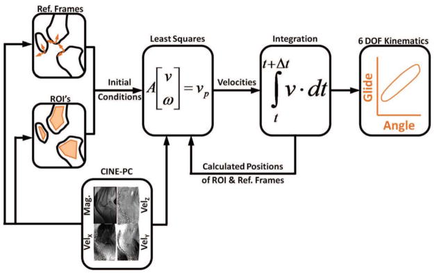
Segment kinematics were obtained by tracking regions of interest (ROIs) within the bone segments. This was done by first identifying all the pixels within each ROI, and then determine the segment translational (v⃑) and angular (ω⃑) velocities that best agreed with measured pixel velocities (v⃑p). Velocity data were then numerically integrated to determine the subsequent position and angular orientation of the segments, and the location of the ROIs. This process was repeated across all frames, thereby producing the 6 degree of freedom (6 DOF) segment kinematic trajectories over the flexion-extension cycle.
Patellofemoral and tibiofemoral joint kinematics were then characterized by the distal segment translations and rotations relative to the proximal segment. Three-dimensional joint angles were determined using a Cardan rotation sequence (body fixed 3-1-2) consisting of flexion, adduction, and internal rotation (Grood and Suntay, 1983). We computed the finite helical axis (FHA) of the tibiofemoral joint assuming rigid body transformations over every 10° increment in knee flexion (Berme et al., 1990; Spoor and Veldpaus, 1980). FHA orientation was characterized by a unit vector, ûFHA, along the axis. FHA position was described by its intersection with the mid-sagittal femoral plane (Sheehan, 2007a). We also digitized the origin and insertion of the patellar tendon with respect to the patella and tibia reference frames, respectively, using the image of the extended knee. The global locations of these points were computed at each time frame and used to ascertain a unit vector, ûPT, along the patellar tendon. The magnitude of the patellar tendon moment arm (rPT) was then computed (Krevolin et al., 2004) by:
| (2) |
where p⃗FHA–PTO is a vector from a point on the FHA to the origin of the patellar tendon line of action. This moment arm, (rPT), represents the tendency of the patellar tendon force to induce a moment about the finite helical axis.
Paired t-tests were used to assess the influence of load (elastic, inertia) on the excursion of each kinematic trajectory over a motion cycle and on the joint translations and rotations at the time of peak knee flexion and extension. A two-way repeated measures ANOVA was used to assess the influence of loading and knee flexion angle on the FHA location and patellar tendon moment arm. The ANOVA analyses were performed separately for FHA and moment arm data extracted during the flexion and extension phases of the motion. Post-hoc analyses were performed using Tukey’s Honest Significance Tests. All statistical analysis was preformed using Statistica (v10, StatSoft Inc., Tulsa., OK) with significance level set at p=0.05.
Results
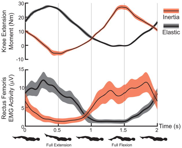
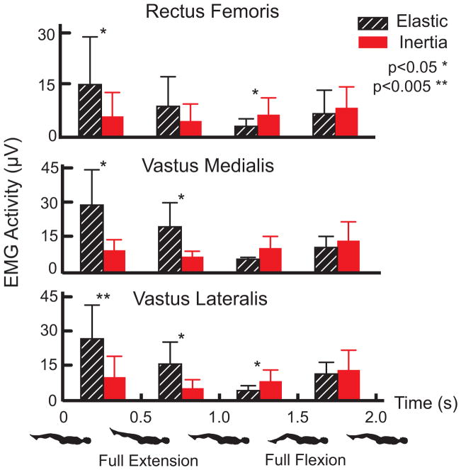
Variations in maximum and minimum knee flexion angles were generally less than 1° over 60 repeat cycles. Peak knee extension moments ranged from 23 to 33 Nm but did not differ significantly between the elastic and inertia loading trials for individual subjects. However, as expected (Appendix A), peak extension moments occurred near the minimum knee flexion angle for the elastic loading condition, while it occurred near maximum knee flexion for the inertia loading condition (Fig. 4). Rectus femoris, vastus medialis and vatus lateralis EMG activity were all significantly larger in extended knee postures for the elastic loading condition (Fig. 5). In contrast, inertial loading induced significantly larger quadriceps activity in a flexed knee posture.
Figure 4.
Average (shaded regions represent ± 1 sd,) knee extension moment and rectus femoris EMG activity for representative elastic and inertial loading trials. Peak quadriceps activity and loading corresponds with knee extension in the elastic case and knee flexion in the inertial case.
Figure 5.
Average (± 1 sd) quadriceps EMG activity during distinct phases of a flexion-extension motion cycle. Elastic loading induced significantly greater EMG activity during all muscles during the last half of knee extension and in the vastii muscles during the first half of knee flexion. Inertial loading induced significant increases in vastus lateralis and rectus femoris activity during the last half of knee flexion. Vastus medialis activity also tended (p=0.06) toward being enhanced in this phase.
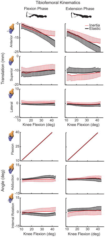
At the point of maximum knee extension, there were no significant load-dependent differences in tibiofemoral kinematics. However, at maximum knee flexion, the tibia was more interiorly translated in the inertial loading condition (p<0.01) (Table 1). As a result, the tibia underwent an average of 5.1 mm less anterior-posterior translation over a flexion-extension cycle in the inertial case (p<0.001) (Fig. 6). Subjects exhibited slightly greater peak knee flexion during elastic loading (47.6°) compared to the inertial (45.7°) condition. There was no significant difference in tibiofemoral adduction or internal tibia rotation between loading conditions.
Table 1.
Mean (SD) tibiofemoral and patellofemoral kinematic measures at the point of maximum knee extension and flexion.
| Joint | Degree of Freedom | @ Maximum Knee Extension | @ Maximum Knee Flexion | Range | ||||||
|---|---|---|---|---|---|---|---|---|---|---|
| Elastic | Inertia | p | Elastic | Inertia | p | Elastic | Inertia | p | ||
| Tibiofemoral | Anterior Translation | −4.0 (1.9) | −4.9 (2.3) | 0.36 | −18.8 (3.8) | −14.6 (3.0) | 0.01* | 14.8 (3.1) | 9.7 (3.5) | 0.001* |
| Superior Translation | −10.6 (3.1) | −11.7 (3.5) | 0.17 | −8.7 (2.8) | −9.5 (3.3) | 0.45 | −1.9 (1.0) | −2.2 (1.0) | 0.41 | |
| Lateral Translation | 0.1 (0.2) | 0.4 (1.1) | 0.37 | −0.3 (1.6) | 0.3 (1.4) | 0.42 | 0.3 (1.6) | 0.2 (1.7) | 0.73 | |
| Flexion | −10.6 (5.3) | −10.6 (5.6) | 0.96 | −47.6 (4.1) | −45.7 (4.0) | 0.03* | 37.1 (6.2) | 35.1 (5.4) | 0.03 * | |
| Adduction | 0.1 (0.3) | −0.6 (1.6) | 0.44 | 1.7 (3.1) | 1.2 (2.5) | 0.67 | −1.9 (3.2) | −1.8 (2.8) | 0.97 | |
| Internal Rotation | 0.0 (1.0) | −1.3 (2.3) | 0.17 | 0.8 (3.7) | 1.4 (3.1) | 0.68 | −0.8 (4.2) | −2.7 (3.8) | 0.24 | |
|
| ||||||||||
| Patellofemoral | Anterior Translation | 29.6 (4.8) | 29.7 (4.7) | 0.94 | 21.7 (5.7) | 24.6 (5.8) | 0.02* | 7.9 (2.6) | 5.0 (2.4) | 0.002* |
| Superior Glide | 16.4 (4.7) | 14.0 (5.1) | 0.05* | −5.1 (7.4) | −1.8 (5.6) | 0.03* | 21.5 (4.5) | 15.8 (4.2) | 0.001* | |
| Lateral Shift | 0.0 (0.8) | −1.8 (2.1) | 0.03* | 1.0 (3.3) | −0.2 (3.6) | 0.18 | −0.9 (3.) | −1.6 (2.8) | 0.41 | |
| Flexion | −5.9 (8.7) | −6.7 (10.3) | 0.42 | −25.2 (9.6) | −21.9 (15.1) | 0.24 | 19.3 (7.2) | 15.2 (7.0) | 0.10 | |
| Adduction | −0.4 (1.5) | 0.3 (1.5) | 0.30 | −5.9 (3.8) | −3.0 (5.8) | 0.25 | 5.5 (4.3) | 3.3 (5.3) | 0.27 | |
| Medial Tilt | 1.1 (6.0) | −0.5 (7.3) | 0.46 | 1.9 (6.8) | 5.4 (14.9) | 0.47 | −0.8 (6.8) | −6.0 (11.7) | 0.19 | |
Significant load effects denoted:
p<0.05
Figure 6.
Shown is the range of 6 degree of freedom tibiofemoral kinematic measures (mean ± 1 sd) seen during the flexion and extension phases of the motion cycles. Substantially reduced anterior tibia translation is seen when quadriceps loading coincides with a flexed posture (inertial case). Non-sagittal tibiofemoral rotations were substantially smaller and did not significantly vary between loading conditions.
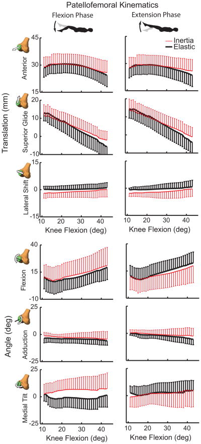
At the patellofemoral (PF) joint, there was significantly (p<0.05) greater anterior and superior patella translation at peak knee flexion in the inertial loading condition compared to the elastic case (Table 1). At peak knee extension, patella glide and lateral patella shift were significantly greater in the elastic case than inertial loading case. As a result, the PF range of motion measures were greater in the elastic case with subjects exhibiting an average of 5.7 mm more patella glide and 2.9 mm more anterior translation (Fig. 7). There were no significant load-dependent variations in patella flexion, adduction or medial tilt.
Figure 7.
Shown are the 6 degree of freedom patellofemoral kinematics (mean ± 1 sd) seen during the flexion and extension phases of the motion cycles. Substantially greater anterior and superior patella translation arises from quadriceps loading in a flexed posture (inertial case). Quadriceps loading with knee extension (elastic case) induced a more laterally oriented patella that was significant in the most extended posture. Hysteresis is evident in the patella rotations with greater medial tilt occurring when the quadriceps loading is increasing with flexion (inertial case).
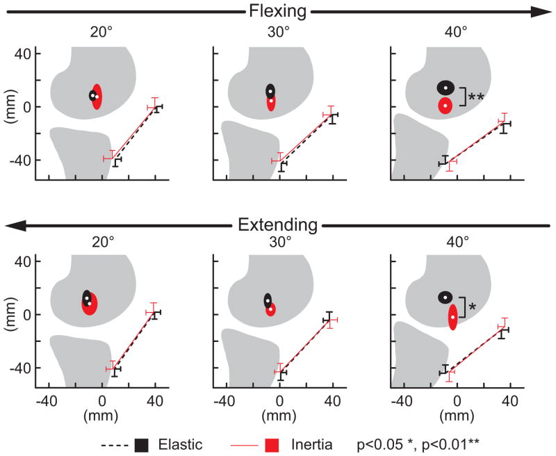
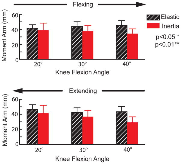
There were no load-dependent variations in the FHA location or patellar tendon moment arm in more extended knee postures. However in a flexed knee posture (40 deg), the FHA was significantly (p<0.05) more distally positioned in the inertial loading condition (Fig. 8). The FHA translation significantly (p<0.05) altered the patellar tendon moment arm in a flexed knee, with the moment arm decreasing from 45±6 mm in the elastic loading condition to 34±6 mm in the inertial case (Fig. 9).
Figure 8.
Shown are the average (±1 sd) origin and insertion of the patellar tendon and the average (±1 sd) location at which the tibiofemoral finite helical axis crossed the mid-sagittal femur. Discrete flexion angles within the flexing and extensing phases of motion are shown. Note the FHA migrated distally with knee flexion when the quadriceps were loaded (inertial case), reducing the moment generating potential of the patellar tendon.
Figure 9.
Shown are the average (±1 sd) patellar tendon moment arm at discrete angles during flexion and extension portions of the motion cycle. Compared to the elastic loading case, the patellar tendon moment arms were significantly reduced when the quadriceps were eccentrically loaded during knee flexion (inertial case).
Discussion
The primary objective of this study was to use dynamic MR imaging to compare in vivo tibiofemoral and patellofemoral kinematics between distinct loading paradigms. Elastic loading was used to induce concentric quadriceps contractions with knee extension, while inertial loading induced eccentric quadriceps contractions with knee flexion. Knee extension moments of ~30 Nm occur with knee flexion during the stance phase of walking (Silder et al., 2008), which is comparable to the inertial loading paradigm (Fig. 2). As expected, subjects exhibited greater anterior tibia translation and superior patella glide when the quadriceps were active and loaded in knee flexion. Biomechanically, this reflects the quadriceps tendon pulling the patella superiorly, and the patellar tendon pulling the tibia interiorly. It was shown that these kinematic variations affected the moment generating capacity of the patellar tendon, which may be important to consider in gait models used to ascertain muscle loading.
The tibiofemoral kinematic patterns we observed are qualitatively similarly to normative values reported in prior cine-PC studies of knee kinematics. In particular, relatively small non-sagittal tibia rotations were observed with knee flexion (Barrance et al., 2005; Barrance et al., 2006; Sheehan et al., 1999). While there was a tendency for external rotation to be enhanced in the inertial loading condition, the difference was not significant. We did observe some significant load-dependent differences in patellofemoral motion. In particular, there was significantly greater lateral shift of the patella in the extended knee in an elastic loading case (Table 1). This result could be due to the patella being less constrained mediolaterally by the trochlea in an extended knee and hence more dependent on relative loading of the vastus lateralis and vastus medialis (Draper et al., 2011; Stensdotter et al., 2003).
The load-dependent changes in knee kinematics had functional ramifications on the knee extensor mechanism. Notably in a flexed knee, quadriceps loading caused the tibiofemoral finite helical axis (FHA) to migrate distally and thereby diminish the patellar tendon’s moment arm. Patellar tendon moment arms were relatively constant (from 41 to 47 mm) in the elastic loading condition but exhibited a significant reduction with flexion (from 41 to 29 mm) in the inertial loading condition. In comparison, moment arms of 40–50 mm have been measured in cadaveric studies at similar knee angles (Buford et al., 1997; Krevolin et al., 2004). A prior dynamic MR imaging study reported slightly smaller in vivo moment arms of 20–40 mm during volitional flexion-extension (Sheehan, 2007b). The latter study was performed without any applied external loads, such that gravity and limb inertia effects may have induced the same decrease in moment arms that we saw in the inertial loading paradigm. A different in vivo study has reported an increase in the patellar tendon moment arm with quadriceps loading (Tsaopoulos et al., 2007), but direct comparison with this study is challenging since their analysis was two-dimensional and moment arms were computed about the tibiofemoral contact point rather than the FHA.
Traditional musculoskeletal simulations of gait do not account for load-dependent changes in moment arms, and instead consider the knee as a 1 degree of freedom joint with secondary motions kinematically coupled to knee flexion (Collins and O’Connor, 1991; Sasaki and Neptune, 2010). Functionally, a change in the patellar tendon moment arm means that it has altered capacity to induce motion about the joint’s screw axis. However, it is not immediately clear what a reduced patellar tendon moment arm would mean for net quadriceps loading since subtle changes in secondary kinematics can also alter cartilage contact location, ligament stretch and the direction and moment arms of other muscles. Hence, the findings of this study support the consideration of a co-simulation framework to account for the simultaneous contributions of cartilage contact, muscle and ligament loads to multi-joint dynamics (Lin et al., 2010).
Limitations of the dynamic MR imaging approach are relevant to consider when interpreting the results. We imaged subjects in a supine posture in order to utilize the high field strength available in closed bore scanners. Upright scanners have the advantage of imaging the knee in a weight bearing posture (Draper et al., 2011; Draper et al., 2008) but have much lower and inhomogeneous magnetic fields limiting the accuracy of cine imaging for tracking 3D segment kinematics. Cine-PC imaging required subjects to perform many repeated cycles of motion to assess kinematic patterns (Barrance et al., 2007; Seisler and Sheehan, 2007; Sheehan et al., 1998). Our motion analysis data showed that subjects could reliably reproduce the net knee motion and overall loading patterns using a MR compatible loading system. We were limited to relatively low loads to allow for the repetition of many cycles. Even so, we were able to induce knee extension moments that are comparable to that seen in normal walking (Silder et al., 2008). Hence, the load-dependent changes in kinematics seem physiologically relevant for a normal intact knee and are likely even more important to consider in knees that have increased laxity due to prior injury or surgery.
In summary, we have shown that significant load-dependent variations in tibiofemoral and patellofemoral kinematics can be observed in vivo using dynamic MRI. These factors may be important to consider when using models to ascertain internal muscle and cartilage loading during functional tasks such as gait.
Supplementary Material
Acknowledgments
We gratefully acknowledge the contributions of Kelli Hellenbrand, Sara John, Eric Bader, Amy Silder, and the financial support of NSF grant 0966535 and NIH grant AR062733.
Footnotes
Conflict of interest statement
There are no conflicts of interest to disclose regarding this study.
Publisher's Disclaimer: This is a PDF file of an unedited manuscript that has been accepted for publication. As a service to our customers we are providing this early version of the manuscript. The manuscript will undergo copyediting, typesetting, and review of the resulting proof before it is published in its final citable form. Please note that during the production process errors may be discovered which could affect the content, and all legal disclaimers that apply to the journal pertain.
References
- Andriacchi TP, Mundermann A, Smith RL, Alexander EJ, Dyrby CO, Koo S. A framework for the in vivo pathomechanics of osteoarthritis at the knee. Ann Biomed Eng. 2004;32:447–457. doi: 10.1023/b:abme.0000017541.82498.37. [DOI] [PubMed] [Google Scholar]
- Arnold EM, Ward SR, Lieber RL, Delp SL. A model of the lower limb for analysis of human movement. Ann Biomed Eng. 2010;38:269–279. doi: 10.1007/s10439-009-9852-5. [DOI] [PMC free article] [PubMed] [Google Scholar]
- Barrance PJ, Williams GN, Novotny JE, Buchanan TS. A method for measurement of joint kinematics in vivo by registration of 3-D geometric models with cine phase contrast magnetic resonance imaging data. J Biomech Eng. 2005;127:829–837. doi: 10.1115/1.1992524. [DOI] [PubMed] [Google Scholar]
- Barrance PJ, Williams GN, Snyder-Mackler L, Buchanan TS. Altered knee kinematics in ACL-deficient non-copers: a comparison using dynamic MRI. J Orthop Res. 2006;24:132–140. doi: 10.1002/jor.20016. [DOI] [PubMed] [Google Scholar]
- Barrance PJ, Williams GN, Snyder-Mackler L, Buchanan TS. Do ACL-injured copers exhibit differences in knee kinematics?: An MRI study. Clin Orthop Relat Res. 2007;454:74–80. doi: 10.1097/BLO.0b013e31802bab0d. [DOI] [PubMed] [Google Scholar]
- Berme N, Cappozzo A, Meglan J. Rigid body mechanics as applied to human movement studies. Biomech of Human Move: Appl in Rehab, Sports, and Ergo. 1990:89–107. [Google Scholar]
- Blankevoort L, Huiskes R, de Lange A. The envelope of passive knee joint motion. J Biomech. 1988;21:705–720. doi: 10.1016/0021-9290(88)90280-1. [DOI] [PubMed] [Google Scholar]
- Buford WL, Jr, Ivey FM, Jr, Malone JD, Patterson RM, Peare GL, Nguyen DK, Stewart AA. Muscle balance at the knee--moment arms for the normal knee and the ACL-minus knee. IEEE Trans Rehabil Eng. 1997;5:367–379. doi: 10.1109/86.650292. [DOI] [PubMed] [Google Scholar]
- Chaudhari AM, Briant PL, Bevill SL, Koo S, Andriacchi TP. Knee kinematics, cartilage morphology, and osteoarthritis after ACL injury. Med Sci Sports Exerc. 2008;40:215–222. doi: 10.1249/mss.0b013e31815cbb0e. [DOI] [PubMed] [Google Scholar]
- Collins JJ, O’Connor JJ. Muscle-ligament interactions at the knee during walking. Proc Inst Mech Eng H. 1991;205:11–18. doi: 10.1243/PIME_PROC_1991_205_256_02. [DOI] [PubMed] [Google Scholar]
- Draper CE, Besier TF, Fredericson M, Santos JM, Beaupre GS, Delp SL, Gold GE. Differences in patellofemoral kinematics between weight-bearing and non-weight-bearing conditions in patients with patellofemoral pain. J Orthop Res. 2011;29:312–317. doi: 10.1002/jor.21253. [DOI] [PMC free article] [PubMed] [Google Scholar]
- Draper CE, Santos JM, Kourtis LC, Besier TF, Fredericson M, Beaupre GS, Gold GE, Delp SL. Feasibility of using real-time MRI to measure joint kinematics in 1.5T and open-bore 0.5T systems. J Magn Reson Imaging. 2008;28:158–166. doi: 10.1002/jmri.21413. [DOI] [PMC free article] [PubMed] [Google Scholar]
- Dyrby CO, Andriacchi TP. Secondary motions of the knee during weight bearing and non-weight bearing activities. J Orthop Res. 2004;22:794–800. doi: 10.1016/j.orthres.2003.11.003. [DOI] [PubMed] [Google Scholar]
- Grood ES, Suntay WJ. A joint coordinate system for the clinical description of three-dimensional motions: application to the knee. J Biomech Engr. 1983;105:136. doi: 10.1115/1.3138397. [DOI] [PubMed] [Google Scholar]
- Kim HJ, Fernandez JW, Akbarshahi M, Walter JP, Fregly BJ, Pandy MG. Evaluation of predicted knee-joint muscle forces during gait using an instrumented knee implant. J Orthop Res. 2009;27:1326–1331. doi: 10.1002/jor.20876. [DOI] [PubMed] [Google Scholar]
- Krevolin JL, Pandy MG, Pearce JC. Moment arm of the patellar tendon in the human knee. J Biomech. 2004;37:785–788. doi: 10.1016/j.jbiomech.2003.09.010. [DOI] [PubMed] [Google Scholar]
- Lafortune MA, Cavanagh PR, Sommer HJ, 3rd, Kalenak A. Three-dimensional kinematics of the human knee during walking. J Biomech. 1992;25:347–357. doi: 10.1016/0021-9290(92)90254-x. [DOI] [PubMed] [Google Scholar]
- Lin YC, Walter JP, Banks SA, Pandy MG, Fregly BJ. Simultaneous prediction of muscle and contact forces in the knee during gait. J Biomech. 2010;43:945–952. doi: 10.1016/j.jbiomech.2009.10.048. [DOI] [PubMed] [Google Scholar]
- Sasaki K, Neptune RR. Individual muscle contributions to the axial knee joint contact force during normal walking. J Biomech. 2010;43:2780–2784. doi: 10.1016/j.jbiomech.2010.06.011. [DOI] [PMC free article] [PubMed] [Google Scholar]
- Seisler AR, Sheehan FT. Normative three-dimensional patellofemoral and tibiofemoral kinematics: a dynamic, in vivo study. IEEE Trans Biomed Eng. 2007;54:1333–1341. doi: 10.1109/TBME.2007.890735. [DOI] [PubMed] [Google Scholar]
- Sheehan F. The finite helical axis of the knee joint (a non-invasive in vivo study using fast-PC MRI) J Biomech. 2007a;40:1038–1047. doi: 10.1016/j.jbiomech.2006.04.006. [DOI] [PubMed] [Google Scholar]
- Sheehan FT. The 3D patellar tendon moment arm: quantified in vivo during volitional activity. J Biomech. 2007b;40:1968–1974. doi: 10.1016/j.jbiomech.2006.09.029. [DOI] [PMC free article] [PubMed] [Google Scholar]
- Sheehan FT. The finite helical axis of the knee joint (a non-invasive in vivo study using fast-PC MRI) J Biomech. 2007c;40:1038–1047. doi: 10.1016/j.jbiomech.2006.04.006. [DOI] [PubMed] [Google Scholar]
- Sheehan FT, Zajac FE, Drace JE. Using cine phase contrast magnetic resonance imaging to non-invasively study in vivo knee dynamics. J Biomech. 1998;31:21–26. doi: 10.1016/s0021-9290(97)00109-7. [DOI] [PubMed] [Google Scholar]
- Sheehan FT, Zajac FE, Drace JE. In vivo tracking of the human patella using cine phase contrast magnetic resonance imaging. J Biomech Eng. 1999;121:650–656. doi: 10.1115/1.2800868. [DOI] [PubMed] [Google Scholar]
- Shelburne KB, Torry MR, Pandy MG. Contributions of muscles, ligaments, and the ground-reaction force to tibiofemoral joint loading during normal gait. J Orthop Res. 2006;24:1983–1990. doi: 10.1002/jor.20255. [DOI] [PubMed] [Google Scholar]
- Silder A, Heiderscheit B, Thelen DG. Active and passive contributions to joint kinetics during walking in older adults. J Biomech. 2008;41:1520–1527. doi: 10.1016/j.jbiomech.2008.02.016. [DOI] [PMC free article] [PubMed] [Google Scholar]
- Silder A, Westphal CJ, Thelen DG. A Magnetic Resonance-Compatible Loading Device for Dynamically Imaging Shortening and Lengthening Muscle Contraction Mechanics. J Med Devices. 2009;3:034504. doi: 10.1115/1.3212559. [DOI] [PMC free article] [PubMed] [Google Scholar]
- Spoor C, Veldpaus F. Rigid body motion calculated from spatial co-ordinates of markers. J Biomech. 1980;13:391–393. doi: 10.1016/0021-9290(80)90020-2. [DOI] [PubMed] [Google Scholar]
- Stensdotter AK, Hodges PW, Mellor R, Sundelin G, Hager-Ross C. Quadriceps activation in closed and in open kinetic chain exercise. Med Sci Sports Exerc. 2003;35:2043–2047. doi: 10.1249/01.MSS.0000099107.03704.AE. [DOI] [PubMed] [Google Scholar]
- Tsaopoulos DE, Baltzopoulos V, Richards PJ, Maganaris CN. In vivo changes in the human patellar tendon moment arm length with different modes and intensities of muscle contraction. J Biomech. 2007 doi: 10.1016/j.jbiomech.2007.05.005. [DOI] [PubMed] [Google Scholar]
- Walker PS, Rovick JS, Robertson DD. The effects of knee brace hinge design and placement on joint mechanics. J Biomech. 1988;21:965–974. doi: 10.1016/0021-9290(88)90135-2. [DOI] [PubMed] [Google Scholar]
- Wilson D, O’Connor J. A three-dimensional geometric model of the knee for the study of joint forces in gait. Gait Posture 1997 [Google Scholar]
- Wilson DR, Feikes JD, Zavatsky AB, O’Connor JJ. The components of passive knee movement are coupled to flexion angle. J Biomech. 2000;33:465–473. doi: 10.1016/s0021-9290(99)00206-7. [DOI] [PubMed] [Google Scholar]
- Zhu Y, Drangova M, Pelc NJ. Fourier tracking of myocardial motion using cine-PC data. Magn Reson Med. 1996;35:471–480. doi: 10.1002/mrm.1910350405. [DOI] [PubMed] [Google Scholar]
Associated Data
This section collects any data citations, data availability statements, or supplementary materials included in this article.


