Abstract
We compared trilinear interpolation to voxel nearest neighbor and distance-weighted algorithms for fast and accurate processing of true 3-dimensional ultrasound (3DUS) image volumes. In this study, the computational efficiency and interpolation accuracy of the 3 methods were compared on the basis of a simulated 3DUS image volume, 34 clinical 3DUS image volumes from 5 patients, and 2 experimental phantom image volumes. We show that trilinear interpolation improves interpolation accuracy over both the voxel nearest neighbor and distance-weighted algorithms yet achieves real-time computational performance that is comparable to the voxel nearest neighbor algrorithm (1–2 orders of magnitude faster than the distance-weighted algorithm) as well as the fastest pixel-based algorithms for processing tracked 2-dimensional ultrasound images (0.035 seconds per 2-dimesional cross-sectional image [76,800 pixels interpolated, or 0.46 ms/1000 pixels] and 1.05 seconds per full volume with a 1-mm3 voxel size [4.6 million voxels interpolated, or 0.23 ms/1000 voxels]). On the basis of these results, trilinear interpolation is recommended as a fast and accurate interpolation method for rectilinear sampling of 3DUS image acquisitions, which is required to facilitate subsequent processing and display during operating room procedures such as image-guided neurosurgery.
Keywords: image-guided neurosurgery, interpolation, rasterization, volumetric 3-dimensional ultrasound
Ultrasound (US) imaging is an important technique with broad utility in both diagnostic and intraoperative navigational applications. Conventional 2-dimensional ultrasound (2DUS) is currently the most commonly used platform, in which multiple freehand sweeps are usually acquired to sample the target tissue. To generate a 3-dimensional (3D) representation of the imaged volume, the position of the US transducer is tracked, and 3D reconstruction algorithms using voxel-, pixel-, and function-based methods1–3are often applied to interpolate image intensities at a set of regularly spaced rectilinear grid points. Cross-sectional 2DUS images are similarly generated either for visualization purposes or for comparison to coregistered 2-dimensional (2D) images of other modalities.
Recently, we integrated true 3-dimensional ultrasound (3DUS) into image-guided neurosurgery, in which the 3DUS image volume is generated from a single acquisition without the need for freehand sweeps or 3D reconstruction, thereby leading to much improved imaging efficiency and volume sampling compared to conventional 2DUS.4 Because the voxels in the volumetric 3DUS acquisition are arranged in an unconventional spherical coordinate system (rather than at the regular Cartesian grid points that most image analysis and processing software handles), image interpolation is required to accurately rasterize the volumetric 3DUS data into a rectilinear 3D image. The creation of a common rectilinear grid of US image intensities for subsequent image processing and visualization is especially important when multiple 3DUS acquisition volumes with partially overlapping fields of view are recorded in rapid succession to sample the surgical volume of interest. Both image interpolation accuracy and computational efficiency are important for clinical applications in the operating room, where real-time or near real-time visualization is essential; thus, the performance characteristics of the algorithm are critical.
In this study, we compared a trilinear interpolation scheme to voxel nearest neighbor and distance-weighted algorithms in terms of interpolation accuracy and computational efficiency. The goal of the study was to identify a simple, accurate, and real-time interpolation method for rapid image processing, analysis, and visualization of true 3DUS image volumes for clinical applications in the operating room. Instead of creating a new interpolation algorithm, we applied existing approaches in a rectilinear parametric space rather than in the physical space of a native volumetric 3DUS data acquisition. Simulated, experimental (phantom), and clinical image volumes were used in the evaluation. The results show that trilinear interpolation is the best choice because it improves interpolation accuracy over both the voxel nearest neighbor and distance-weighted algorithms while achieving computational efficiencies comparable to those of the voxel nearest neighbor algorithm. In the following sections, we introduce the coordinate system used to acquire the native 3DUS data, summarize the interpolation schemes involved in the trilinear interpolation, voxel nearest neighbor, and distance-weighted algorithms, and present the accuracy and efficiency findings from the performance evaluation.
Materials and Methods
Three-Dimensional Ultrasound Coordinate System
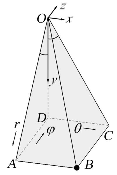
Understanding the coordinate system used to acquire the native 3DUS data is necessary for establishing the coordinate transformations required for subsequent rectilinear grid interpolation. Voxels in volumetric 3DUS images obtained from the US system used in the study (iU22; Philips Healthcare, Bothell, WA) are arranged in an unconventional spherical coordinate system (its transformation to/from a Cartesian coordinate system differs from a traditional spherical coordinate system5; see Equations 1–3) in which a radial distance relative to the origin O (r, in millimeters), a lateral angle (θ, in degrees), and a medial angle (φ, in degrees) define a voxel location (Figure 1). A typical voxel in a 3DUS image (point Bin Figure 1) is specified by a triplex (ir, jθ, kφ), where each element denotes an index within the rows, columns, and slices of the 3D image matrix, respectively. The dimensions of the 3D matrix (ie, the number of rows, columns, and slices) and the physical ranges of the scan depth (in millimeters) and lateral and medial angles (in degrees) determine the step sizes of r, θ, and φ, respectively. Together with the step sizes, the indices of the voxel in the image matrix determine the location of the voxel (r, θ, φ) in physical space, where r is the distance from the origin, whereas θ and φ are the angles between the vertical axis OD (the corresponding θ and φ values are both 0) and planes OBC and OAB, respectively (Figure 1). Voxels of an iso-θor iso-φvalue are on a plane, whereas voxels of an iso-r value are equidistant from the origin. In the figure shown, we have the following geometric relationships: OB = r; AD = z; CD = x; OD = y; CD ˔ OD, and AD˔OD. In addition, the quadrilateral ABCD is a rectangle, which leads to
| (1) |
With further manipulation, the Cartesian coordinates (x, y, z) of the voxel are determined from the triplex in image space (r, θ, φ) according to
| (2) |
Conversely, from the Cartesian coordinates (x, y, z) of a voxel, the image coordinates (r, θ, φ) are given by
| (3) |
All of the volumetric 3DUS images evaluated in this study were acquired using a dedicated transducer (X3-1 broad-band matrix array with a 1–3 MHz operating frequency) connected to the iU22 system, which produces volumetric US images in the Digital Imaging and Communications in Medicine format. All 3DUS images were digitally retrieved from the US system through a dedicated communications network. All acquisitions were configured to cover the maximum angular ranges allowable (−42.9° to 44.4° in θ and −36.6° to 36.6° in φ, respectively). For clinical images, the scan depth was set at 140 to 160 mm to capture the parenchymal surfaces contralateral to the craniotomy, whereas an optimal scan depth of 90 mm was used to acquire the experimental phantom images (see “Performance Evaluation” section for details). The dimensions of a typical 3DUS image matrix were 368 × 70 × 46, resulting in step sizes of 1.27° and 1.63° in θ and φ, respectively, whereas the step size in r depended on the scan depth.4
Figure 1.
Coordinate system of a typical 3-dimensional ultrasound image, in which a typical voxel (B) is specified by its coordinates (r, θ, φ).
Geometric Transformation and Trilinear Interpolation
A volumetric 3DUS image is mathematically represented as a 3D matrix. A parametric space is then defined as a rectilinear coordinate system where each axis spans from 1 to the respective dimension of the image matrix (ie, the number of rows, columns, and slices). The coordinates (i, j, k; not necessarily integers) of an arbitrary location in parametric space that does not necessarily coincide with a grid point, together with the step sizes of r, θ, and φ, uniquely determine the coordinates in physical space, in ways similar to voxels located at grid points (Equation 2). Conversely, for an arbitrary point in physical space (p in Figure 2a), the corresponding point in parametric space (p’ in Figure 2b) can be uniquely determined (Equation 3). This one-to-one mapping establishes the geometric transformation between the 2 spaces, allowing the 8 neighboring voxels relative to p to be easily identified.6 In addition, these neighboring voxels form an 8-node hexahedral element in parametric space, and the intensity value at p or its equivalent, p’, can then be linearly interpolated using standard finite element trilinear shape functions.7
Figure 2.
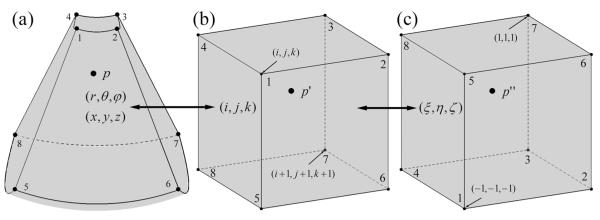
Sequential transformations of a typical point from physical space (a; p, shown in a frustum-shaped volume formed by the 8 surrounding voxels) to parametric space (b; p’), and subsequently to natural coordinates (c; p”) of a hexahedral element determined by the 8 surrounding voxels. The image intensity at p is interpolated through the standard trilinear shape functions for a normalized hexahedral element at p” in natural coordinates.
Specifically, the hexahedral element in parametric space is further transformed into natural coordinates as in the standard finite element method (Figure 2c7). The trilinear shape functions for a normalized hexahedral element are expressed as
| (4) |
where a spans from 1 to 8, representing the 8 nodes, whereas ξ, η, and ζ are 3 normalized coordinates each extending from −1 to 1 (the subscript indicates the coordinate value at node a). Thus, in the trilinear interpolation algorithm, the intensity at p is calculated as the weighted sum of the intensities at the neighboring voxels according to the equation (Figure 2c)
| (5) |
where I(a) is the intensity value of the voxel associated with node a.
Voxel Nearest Neighbor and Distance-Weighted Interpolation
To evaluate the computational efficiency and interpolation accuracy of trilinear interpolation, voxel nearest neighbor1–3 and distance-weighted (analogous to that described by Trobaugh et al8) interpolation algorithms were also implemented. For the voxel nearest neighbor algorithm, image intensity at p was set to the value of the closest voxel in Figure 2b. For the distance-weighted algorithm, a typical point, p, was first projected onto the 2 closest iso-θ planes (Figure 3), and the respective quadrilaterals enclosing the resulting planar projections (Xi; i = 1, 2) were obtained. In order to use the same interpolation method as Trobaugh et al,8 the planar projections were further projected onto the straight sides of the respective quadrilateral. The image intensities at the edge projections (Xij; i, j = 1, 2), planar projections (Xi), and eventually at p were calculated sequentially on the basis of the distance-weighting algorithm (Figure 3).
Figure 3.

Distance-weighted interpolation for 3-dimensional ultrasound images. A typical point in physical space, p, was projected onto the 2 closest iso-θ planes, and the resulting projection points were further projected onto the straight edges of the respective quadrilaterals. I(Xij), I(Xi), and I(p) in the equations are image intensities at the edge projections, planar projections, and the interpolation point, respectively.
In total, 8 surrounding voxels contribute to the image intensity at p using trilinear interpolation and the distance-weighted algorithm, whereas only the closest voxel contributes to the voxel nearest neighbor algorithm. For the distance-weighted algorithm, degenerative cases (eg, when p is on the volumetric boundary in Figure 2a) are also properly handled. Here, the shape functions (Equation 4) used in trilinear interpolation are continuous in parametric space and generate a continuous interpolation throughout the physical space.
Performance Evaluation
To evaluate the interpolation accuracy as well as the computational efficiency of the trilinear interpolation, voxel nearest neighbor, and distance-weighted algorithms, simulated, clinical, and experimental phantom images were investigated. A simulated 3DUS image was created by setting voxel intensities proportional to the voxel distances from the origin (ie, image intensity linearly varied within the imaging volume: 1.2 million voxels). A set of randomly generated points (n = 10,000) and their ground-truth intensities (explicitly determined by the distance relative to the origin) were used to evaluate the interpolation error. The interpolation error (IE) was defined as the average absolute difference of image intensities between the interpolated and ground-truth images1:
| (6) |
where and are the interpolated and ground-truth image intensities of the kth voxel, and Nv is the total number of voxels in the image volume. Using the simulated data, an exact interpolation (IE < 10−13) was achieved with the trilinear interpolation algorithm as expected because the linearity of the interpolation perfectly matched the true image intensities,7 which validated the algorithm’s implementation.
Clinical images from 5 patients (3 male and 2 female; average age, 53 years) undergoing open cranial brain tumor (including 3 low-grade gliomas, 1 high-grade glioma, and 1 meningioma) resections with deployment of volumetric 3DUS were evaluated. After craniotomy but before dural opening, a set of volumetric 3DUS images (8 bits in gray intensity, 1.2 million voxels for each image) was acquired (the number of acquisitions for each patient typically ranged from 3 to 9, resulting in a total of 34 3DUS volumes). To evaluate the interpolation error with clinical images, we used a scheme similar to the concept of “leave one out” by retaining only voxels with odd-numbered indices of r for interpolation and using even-numbered indices of r as the ground-truth intensities for comparison. The step size of r was doubled to maintain the image integrity (ie, to ensure that voxels in the resulting image volume were transformed to the same physical locations in the Cartesian coordinate system compared to their counterparts in the original image).
Two 3DUS phantom image volumes were generated from a group of carrots submerged in a water tank (Figure 3a) as another accuracy evaluation experiment in a fixed geometry of discrete objects that could be carefully controlled. The effects of air bubbles in the water were minimized with an in-house degasser system similar to that described by Kaiser et al,9 operated continuously for 1 hour before image acquisition. The degasser consisted of a standard pump, a customized degassing head with twelve 0.51-mm holes, and common laboratory tubing. The 2 images were acquired by placing the US transducer at 2 distinct but nearby locations (≈5 mm apart), and image acquisitions were performed at least 5 minutes after the US transducer was repositioned to minimize water movement. Positional trackers were rigidly attached adjacent to the water tank (“patient tracker” in Figure 4a) and to the US transducer, respectively. Both trackers were continuously monitored by an optical digitizer (Polaris; Northern Digital, Inc, Toronto, Ontario, Canada), which established a common world coordinate system through which the second 3DUS image volume was transformed into the coordinate system of the first (Figure 4b). The details of the optical tracking system and coordinate transformations have been described in detail elsewhere.10 Image intensities in the first image volume were interpolated to locations defined by the transformed voxels in the second image acquisition using the 3 interpolation algorithms. These phantom images, although not fully representative of the effects in tissue, likely present a challenging scenario for evaluation of interpolation accuracy because of the strong mismatch in acoustic impedance at the water-carrot interfaces that caused considerable specular reflections, which are typically lacking in US images of soft tissue (but are similar to the US images we routinely acquire from the brain-skull interface opposite to the cranial opening during surgery). Future phantom studies would benefit from the use of better tissue-mimicking materials (eg, gelatin and agar) to evaluate interpolation accuracy within embedded structures, in which case variations in the speed of sound must be considered to correctly interpolate the imaging results. In this work, image artifacts from speed of sound variations were likely negligible because only the water-carrot interface (as opposed to interior features) was evident. The interpolation accuracies of the 3 algorithms were compared quantitatively by computing the interpolation error in Equation 6, where the image intensities in the second volume acquisition served as the ground truth (the change in the phantom angular position in the US images was negligible because of the small change in the US transducer position).
Figure 4.
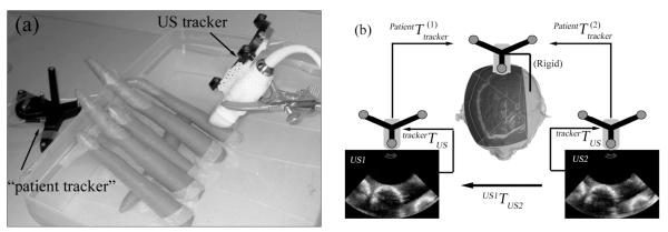
a, Layout of the phantom image acquisition experiment. b, Image transformation from the second 3DUS image into the coordinate system of the first.
Finally, we randomly generated cross-sectional 2DUS images (n = 100) of 320 × 240 in size using the trilinear interpolation, voxel nearest neighbor, and distance-weighted algorithms (image size identical to that described by Gobbi and Peters11) and compared the computational costs with 2 of the fastest interpolation algorithms using pixel-based methods for 2DUS images.3 The computational cost of generating a full rasterized volume with a voxel size of 1 mm3 from a representative clinical image with a scan depth of 140 mm was also determined.
All interpolation algorithms were implemented in C and compiled into MATLAB executables (MATLAB R2008b; The Mathworks, Natick, MA), which were dynamically linked with identical computational efficiency to execution of the natively compiled C codes. All computations were performed on a Xeon computer (Intel Corporation, Santa Clara, CA) running Ubuntu 6.10 (2.33 GHz, 8 GB RAM; Canonical Group, Ltd, London, England).
Results
Using the simulated data, trilinear interpolation had computational efficiency comparable to that of the voxel nearest neighbor algorithm but was 6 times faster than the distance-weighted algorithm (Table 1).
Table 1.
Absolute and Normalized Computational Costs for Trilinear (TRI), Voxel Nearest Neighbor (VNN), and Distance-Weighted (DW) Interpolation Algorithms Using a Simulated 3-Dimensional Ultrasound Image
| Parameter | TRI | VNN | DW |
|---|---|---|---|
| Time, s | 0.019 | 0.015 | 0.12 |
| Normalized time, ms/1000 voxels | 1.9 | 1.5 | 12 |
The image had 1.2 million voxels, and performances of 10,000 voxel interpolations were evaluated.
Using clinical 3DUS images to interpolate intensities at even-numbered indices of r, trilinear interpolation maintained a computational cost similar to that of the voxel nearest neighbor algorithm but required only 2.6% of the time needed for the distance-weighted algorithm (Table 2). Again, trilinear interpolation reduced the interpolation error relative to the voxel nearest neighbor and distance-weighted algorithms, showing the superiority of the scheme. The interpolation error of the distance-weighted algorithm by essentially removing half of the voxels was similar to that reported by Rohling et al1 for a thyroid examination using the same interpolation algorithm (ie, distance-weighted).
Table 2.
Absolute and Normalized Computational Costs and Interpolation Error for Trilinear (TRI), Voxel Nearest Neighbor (VNN), and Distance-Weighted (DW) Interpolation Algorithms Using Clinical 3-Dimensional Ultrasound Volumese
| Parameter | TRI | VNN | DW |
|---|---|---|---|
| Time, s | 0.20 ± 0.01 | 0.17 ± 0.01 | 7.74 ± 0.34 |
| Normalized time, ms/1000 voxels | 0.34 | 0.29 | 13.1 |
| Interpolation error | 5.95 ± 1.59 | 17.90 ± 19.49 | 7.33 ± 1.68 |
Time and interpolation error values are mean ± SD. Data were averaged from 34 volumes acquired in 5 patients; each volumetric image had 1.2 million voxels, and performances of 592,500 voxel interpolations were evaluated.
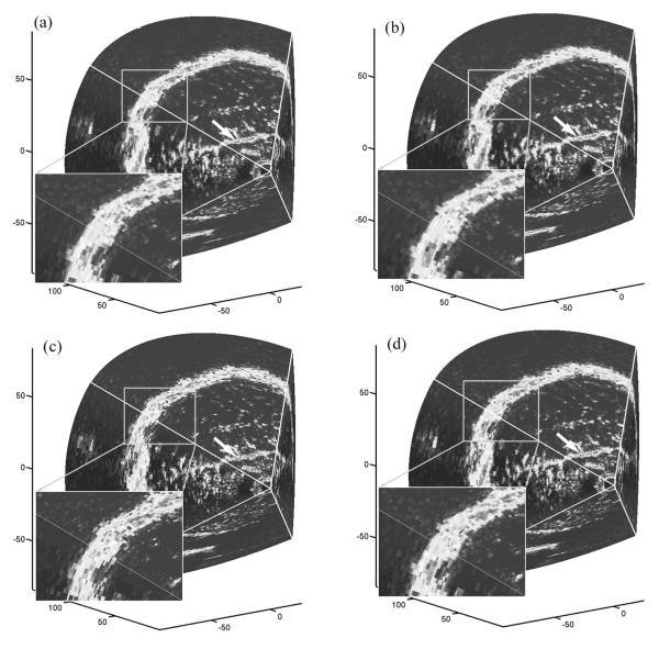
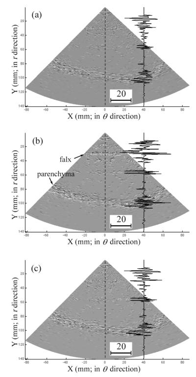
To visually compare the differences in interpolation error, boundaries from a typical clinical 3DUS image volume are shown by retaining only the even-numbered indices of r for comparison to images interpolated with the trilinear interpolation, voxel nearest neighbor, and distance-weighted algorithms (Figure 5). Relative to the ground truth (ie, image intensities at the even-numbered indices of r from the acquired 3DUS images), trilinear interpolation reduced the interpolation error over the voxel nearest neighbor algorithm especially in regions near the parenchymal surface and the falx (see the magnitude of the image intensity difference relative to ground truth along the dashed line in the difference images of Figure 6) while being visually comparable to the distance-weighted algorithm.
Figure 5.
Visualization of boundaries in a typical clinical 3DUS image using the even-numbered indices of r as the ground truth (a) and the corresponding boundaries interpolated with the trilinear interpolation (b), voxel nearest neighbor (c), and distance-weighted (d) algorithms. Differences at the parenchymal surface (enlarged) and the falx (arrow) are evident. Axis units are millimeters.
Figure 6.
Difference images corresponding to the top surfaces of Figure 4, b–d, with respect to the ground truth shown in Figure 4a. a, Trilinear interpolation algorithm. b, Voxel nearest neighbor algorithm. c, Distance-weighted algorithm. Representative curves in each image show the respective image difference (interpolated image subtracting the ground-truth image) as a function of the radial position from the origin along the dashed line (the scale of the image difference is also shown).
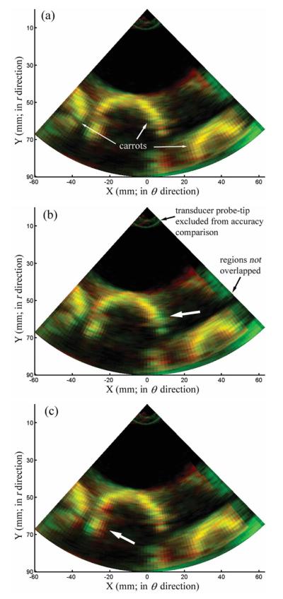
By transforming the second phantom image into the coordinate system of the first to interpolate image intensities at locations defined by the transformed voxels, the relative interpolation error resulting from the 3 algorithms can be visually compared by generating composite overlays with the ground-truth image (ie, the second image acquired). In the composite 2D red-green-blue images shown in Figure 7, the interpolated and ground-truth images were set to the red and green channels, respectively. The closer the interpolated image intensity was to the corresponding ground-truth value, the closer the corresponding color-coded pixel in the composite image appears as yellow in Figure 6. Apparently, trilinear interpolation generated a composite image with more dominant yellow pixels compared to that produced by the voxel nearest neighbor or distance-weighted algorithm (thick arrows in Figure 6, b and c), indicating its superior interpolation accuracy, which confirms its smaller interpolation error in Table 3. Voxels near the probe tip (voxel distance relative to the origin, <20 mm) or in regions not overlapped with the first phantom image were excluded from the evaluation of interpolation error. Similarly to the clinical images, the computational efficiency of trilinear interpolation was comparable to that of the voxel nearest neighbor algorithm but was 2 orders of magnitude faster than the distance-weighted algorithm (Table 3).
Figure 7.
Interpolated image (red) obtained from the trilinear interpolation (a), voxel nearest neighbor (b), and distance-weighted (c) algorithms overlaid against its corresponding ground-truth image (green, ie, the second phantom image being transformed). Only 2-dimensional iso-φ images are shown. Thick arrows in b and c indicate regions with fewer yellow pixels compared with their counterparts in a, suggesting superior interpolation accuracy with the trilinear interpolation algorithm.
Table 3.
Absolute and Normalized Computational Cost and Interpolation Error Resulting From Trilinear (TRI), Voxel Nearest Neighbor (VNN), and Distance-Weighted (DW) Interpolation Algorithms Using Phantom Images
| Parameter | TRI | VNN | DW |
|---|---|---|---|
| Time, s | 0.29 | 0.26 | 11.93 |
| Normalized time, ms/1000 voxels | 0.25 | 0.22 | 10.1 |
| Interpolation error | 10.9 ± 15.1 | 14.3 ± 18.4 | 12.6 ± 16.6 |
Interpolation error values are mean ± SD. Each image had 1.2 million voxels to interpolate.
The average computational costs using the trilinear interpolation, voxel nearest neighbor, and distance-weighted algorithms to generate cross-sectional 2DUS images are reported in Table 4 (SD, ≈10−4; not shown) and are compared to some of the fastest pixel-based interpolation methods published to date.3
Table 4.
Average Computational Costs for Trilinear (TRI), Voxel Nearest Neighbor (VNN), and Distance-Weighted (DW) Interpolation Algorithms When Generating Cross-sectional 2-Dimensional Ultrasound Images Compared With 2 of the Fastest Pixel-Based Algorithms3,11
| Parameter | TRI | VNN | DW | Real-time PNN | Real-time PTL |
|---|---|---|---|---|---|
| Time, s | 0.035 | 0.028 | 1.01 | 0.033 | 0.05 |
| Normalized time, ms/1000 pixels | 0.46 | 0.36 | 13.2 | 0.43 | 0.65 |
Each image had 76,800 pixels to interpolate. PNN indicates pixel nearest neighbor interpolation11; and PTL, pixel trilinear interpolation via alpha blending.11
Finally, we generated a full-volume 3D representation of a typical clinical image (scan depth of 140 mm) rasterized at a set of regularly spaced grid points (image matrix size of 193 × 141 × 168 [ie, 4.6 million voxels in total], resulting in a voxel size of 1 × 1 × 1 mm) using the 3 algorithms. The computational costs were 1.05, 1.03, and 53.76 seconds for the trilinear interpolation, voxel nearest neighbor, and distance-weighted algorithms, respectively, averaged from 100 independent runs (normalized computational cost of 0.23, 0.22, and 11.7 ms/1000 voxels, respectively).
Discussion
We have implemented and compared 3 interpolation algorithms for rapid processing of true 3DUS image volumes acquired from a dedicated US transducer. The interpolation accuracy of clinical 3DUS image volumes was evaluated by retaining half of the voxels for interpolation, whereas the remainder was used for ground-truth comparison. The r indices of the remaining voxels in parametric space were precisely n+ 0.5, where n was an integer. To evaluate interpolation accuracy at arbitrary locations, we also acquired two 3DUS images of a phantom under conditions that were not possible to control in the operating room, one of which was selected to determine a parametric space, whereas the other (transformed into the image coordinate system of the first) supplied the ground truth.
The trilinear interpolation algorithm achieved computational efficiency comparable to that of the voxel nearest neighbor algorithm but with substantially improved interpolation accuracy. It had slightly better interpolation accuracy relative to the distance-weighted algorithm but computational efficiency that was 1 to 2 orders of magnitude faster than the distance-weighted algorithm. The computational efficiency of trilinear interpolation was also comparable to that of the fastest pixel-based algorithms for tracked 2DUS images published in the literature.3 It generated a cross-sectional 2DUS image (76,800 pixels) in 0.035 seconds relative to 0.033 and 0.05 seconds for pixel nearest neighbor interpolation and pixel trilinear interpolation via alpha blending, respectively. Both the trilinear interpolation and voxel nearest neighbor algorithms use an explicit geometric transformation that allows interpolation to be performed in parametric space instead of physical space, in which case standard shape functions associated with finite elements can be directly applied. The explicit geometric transformation that maps points for interpolation from physical space into parametric space is essential to achieving the real-time performance of the algorithms. In fact, the trilinear interpolation algorithm was only marginally slower than the voxel nearest neighbor algorithm for all of the performance evaluations in this study (Tables 1–4) because both methods use the same geometric transformation, which consumes a large fraction of the total computational costs associated with each technique.
Because interpolation is involved, trilinear interpolation is likely to be more accurate than pixel nearest neighbor interpolation, which only uses the nearest pixels in ways similar to those of the voxel nearest neighbor algorithm and is likely to be similar to pixel trilinear interpolation via alpha blending because of the linear nature of both methods, but actual validation studies have not been performed and would be required to confirm these expectations. Furthermore, trilinear interpolation is simple to implement and calculates image intensities directly without the need to traverse pixels or “fill holes,” as required by pixel-based methods, in which the type and size of the interpolation kernel must be empirically determined beforehand.3 Unlike pixel-based methods in which the computational complexity depends on the numbers of interpolation points and input images, the computational complexity of trilinear interpolation only depends on the number of interpolation points [ie, O(N) complexity]. Therefore, trilinear interpolation is also expected to be more efficient than the pixel-based algorithms when multiple 3DUS images are used to create a single rasterization over the combined image volumes. Although trilinear interpolation may introduce new intensity values that are not present in the original image acquisition, which could adversely affect certain types of subsequent image processing such as mutual information computations,12 it tends to reduce the level of noise because of its weighted averaging (ie, Equation 5), which is similar to mean filtering and typically beneficial to further processing.
All of the interpolation algorithms used here can be implemented with graphics processing units to take advantage of multithreading, which would considerably increase their computational efficiency even further (a factor of 1–2 orders of magnitude of gain in speed is expected13). With the growing popularity of graphics processing units for scientific computing, we anticipate that more advanced interpolation schemes could be implemented (eg, quadratic or cubic forms) that would improve interpolation accuracy further while maintaining real-time performance.
In summary, trilinear interpolation is recommended as a fast and accurate interpolation method for rectilinear sampling of 3DUS image acquisitions, which is required to facilitate subsequent processing and display during operating room procedures such as image-guided neurosurgery.
Acknowledgments
This work was funded by National Institutes of Health grant R01 EB002082-11. Support for the iU22 ultrasound system was provided by Philips Healthcare (Bothell, WA).
Abbreviations
- 3D
3-dimensional
- 3DUS
3-dimensional ultrasound
- 2D
2-dimensional
- 2DUS
2-dimensional ultrasound
- US
ultrasound
References
- 1.Rohling R, Gee A, Berman L. A comparison of freehand three-dimensional ultrasound reconstruction techniques. Med Image Anal. 1999;3:339–359. doi: 10.1016/s1361-8415(99)80028-0. [DOI] [PubMed] [Google Scholar]
- 2.Fenster A, Downey DB, Cardinal HN. Three-dimensional ultrasound imaging. Phys Med Biol. 2001;46:R67–R99. doi: 10.1088/0031-9155/46/5/201. [DOI] [PubMed] [Google Scholar]
- 3.Solberg OV, Lindseth F, Torp H, Blake RE, Nagelhus Hernes TA. Free-hand 3D ultrasound reconstruction algorithms: a review. Ultrasound Med Biol. 2007;33:991–1009. doi: 10.1016/j.ultrasmedbio.2007.02.015. [DOI] [PubMed] [Google Scholar]
- 4.Ji S, Hartov A, Fontaine K, Borsic A, Roberts D, Paulsen K. Coregistered volumetric true 3D ultrasonography in image-guided neurosurgery. In: Miga MI, Cleary KR, editors. Medical Imaging 2008: Visualization, Image-Guided Procedures, and Modeling. Proceedings of SPIE. Vol 6918. SPIE; Bellingham, WA: 2008. p. 69180F. [Google Scholar]
- 5.McQuarrie DA. Mathematical Methods for Scientists and Engineers. University Science Books; Herndon, VA: 2003. [Google Scholar]
- 6.Duan Q, Angelini E, Song T, Laine A. Fast interpolation algorithms for real-time three-dimensional cardiac ultrasound. Proceedings of the 25th Annual International Conference of the Institute of Electrical and Electronics Engineers Engineering in Medicine and Biology Society; Piscataway, NJ: Institute of Electrical and Electronics Engineers; 2003. pp. 1192–1195. [Google Scholar]
- 7.Zienkiewicz OC, Taylor RL, Zhu JZ. The Finite Element Method: Its Basis and Fundamentals. 6th ed Elsevier Butterworth-Heinemann; Oxford, England: 2005. [Google Scholar]
- 8.Trobaugh JW, Trobaugh DJ, Richard WD. Three-dimensional imaging with stereotactic ultrasonography. Comput Med Imaging Graph. 1994;18:315–323. doi: 10.1016/0895-6111(94)90002-7. [DOI] [PubMed] [Google Scholar]
- 9.Kaiser AR, Cain CA, Hwang EY, Fowlkes JB. Cost-effective degassing system for use in ultrasonic measurements: the multiple pinhole degassing system. J Acoust Soc Am. 1996;99:3857–3859. [Google Scholar]
- 10.Ji S, Wu Z, Hartov A, Roberts DW, Paulsen KD. Mutual-information-based image to patient re-registration using intraoperative ultrasound in image-guided neurosurgery. Med Phys. 2008;35:4612–4624. doi: 10.1118/1.2977728. [DOI] [PMC free article] [PubMed] [Google Scholar]
- 11.Gobbi DG, Peters TM. Interactive intra-operative 3D ultrasound reconstruction and visualization. Med Image Comput Comput Assist Intervention. 2002;2489:156–163. [Google Scholar]
- 12.Maes F, Collignon A, Vandermeulen D, Marchal G, Suetens P. Multimodality image registration by maximization of mutual information. IEEE Trans Med Imaging. 1997;16:187–198. doi: 10.1109/42.563664. [DOI] [PubMed] [Google Scholar]
- 13.Owens JD, Houston M, Luebke D, Green S, Stone JE, Phillips JC. GPU computing. Proceedings ofIEEE. 2008;96:879–899. [Google Scholar]


