Abstract
An upgraded optical coherence tomography system with integrated retinal tracker (TOCT) was developed. The upgraded system uses improved components to extend the tracking bandwidth, fully integrates the tracking hardware into the optical head of the clinical OCT system, and operates from a single software platform. The system was able to achieve transverse scan registration with sub-pixel accuracy (~10 μm). We demonstrate several advanced scan sequences with the TOCT, including composite scans averaged (co-added) from multiple B-scans taken consecutively and several hours apart, en face images collected by summing the A-scans of circular, line, and raster scans, and three-dimensional (3D) retinal maps of the fovea and optic disc. The new system achieves highly accurate OCT scan registration yielding composite images with significantly improved spatial resolution, increased signal-to-noise ratio, and reduced speckle while maintaining well-defined boundaries and sharp fine structure compared to single scans. Precise re-registration of multiple scans over separate imaging sessions demonstrates TOCT utility for longitudinal studies. En face images and 3D data cubes generated from these data reveal high fidelity image registration with tracking, despite scan durations of more than one minute.
1. Introduction
New high speed and high resolution optical coherence tomography systems have been reported that use alternate scan patterns or Fourier domain techniques to acquire nontraditional scans and full three-dimensional (3D) maps of the human retina. Podoleanu et al. have built low coherence systems that scan in a raster pattern – as is done with a scanning laser ophthalmocope – to create an en-face retinal view, and then step in depth to create the 3D maps [1]. Fourier domain methods, in which a spectrometer is placed in the detector arm of the interferometer to simultaneously collect light from all range gates within the A-scan, have also been applied to retinal imaging [2, 3]. Nassif, Cense, and others have used high speed Fourier domain systems to acquire conventional OCT cross-sections and step along the transverse axis to build a 3D map [4, 5]. Acquisition of full retinal maps will provide a more extensive picture of ocular health to ophthalmologists, increase the sensitivity and specificity for diagnosis of many types of retinal pathologies, and lead to improved determination of efficacy for current and future treatments of retinal diseases.
It is clear from these investigations that the main limitation to routine collection of high density 3D maps in a clinical environment is eye motion. Back-scattered light must be collected with sufficient signal-to-noise within the limitations imposed by laser safety standards and the subject’s fixational ability. The en-face systems do this by re-ordering the scans so the fast scan is along the transverse dimension where eye motion is prevalent. Fourier domain systems use their multiplexed advantage to acquire high speed scans up to two orders of magnitude faster than their time domain counterparts. Cross-sectional images can be acquired in as little as tens of milliseconds but full retinal maps still take several seconds to acquire. These systems have changed the point where eye movements begin to corrupt the image: motion artifacts that used to perturb OCT B-scans are less problematic in cross-sectional imaging but now perturb OCT C-scans in 3D imaging. We demonstrate that if eye motion can be controlled, these advanced scan types can be collected with any OCT instrument. Retinal tracking essentially removes limitations related to scan duration from consideration by rendering the target stationary.
In prior work, we reported the development of a prototype clinical optical coherence tomography system with integrated retinal tracker (TOCT) [6, 7]. We demonstrated the capability of TOCT to stabilize the eye during OCT scans, between scans, and permit precise re-registration of scans in successive visits in glaucoma patients. In any OCT system, the same scan path is very difficult to repeat without reference to fixed retinal coordinates provided by tracking. Software A-scan depth registration and averaging revealed superior OCT image detail with tracking. Without tracking, transverse registration error and associated vertical alignment algorithm errors led to blur and image distortions.
In this paper, we report initial clinical results from an upgraded TOCT system. The new system uses a Status OCT platform with higher scan speed and resolution, a more compact, higher speed tracking system, and new scan patterns that exploit the real time scan registration made possible with retinal tracking. In order to determine the effectiveness of tracking on acquisition of OCT images in a clinical setting, testing in human volunteers with normal and diseased eyes is underway at UPMC Eye Center, University of Pittsburgh School of Medicine. In this paper, we look at preliminary results obtained from two subjects with normal eyes using several non-standard scans.
2. Materials and methods
In previous reports, we describe the integration of a hardware-based active retinal tracker into a second generation clinical optical coherence tomographer manufactured by Carl Zeiss Meditec Inc. (CZMI [6, 7]. That system underwent preliminary clinical trials in subjects with normal and glaucomatous eyes. We assessed the ability to track eye movements and generate cross-sections at fixed retinal coordinates using a standard protocol for multiple scans within a visit and over multiple visits [7]. Despite the low transverse resolution of the OCT scans (107 μm for the standard 3.4 mm diameter peripapillary scan and 59 μm for the radial line scans), we found that the variance in scan-to-scan position was less than 1 pixel for standard landmarks with well-defined edges (e.g., optic cup, foveal pit). Tracking was stable on all but one subject (92% of subjects tested) who had spontaneous venous pulsation.
The system described herein uses a retinal tracking integrated into a third generation clinical OCT system (Stratus OCT, CZMI). The Stratus OCT system has many improvements over its predecessors, most notably increased transverse resolution (21 μm for the standard 3.4 mm diameter peripapillary scan), faster A-scan rates (400 A-scans/sec), and advanced acquisition and analysis software.
The retinal tracker operates on the same principle as previously described tracking scanning laser ophthalmoscopy (TSLO) and TOCT systems [6–11]. The optical layout is illustrated in Fig. 1. The tracker dithers a secondary beam on a retinal target with a pair of resonant scanner (RS, Electro-Optical Products Corp.) and detects reflectivity changes in the target with a confocal reflectometer. The detected signal is processed with a real-time data acquisition processor (DAP, Microstar Laboratories Inc.) and fed back to two galvanometer-driven mirrors (TG, Cambridge Technology Inc.) through which the OCT beam passes. As the eye rotates, the system senses reflectivity changes at the dither frequency, generates error signals, and drives the galvanometer-driven mirrors to null the error. The optical beam path of the Stratus OCT system was not altered except for the changes involved in integration of the retinal tracker. These changes include addition of a dichroic beamsplitter, D2 (T>90% above 900 nm, T<10% below 860 nm, Barr Associates) and two tracking mirrors (enhanced silver coating, ~96% reflective at all wavelengths used) and use of a new dichroic beamsplitter, D1, to reflect the longer wavelength tracking beam. Total round-trip losses in SLD power amount to 10–15% with inclusion of the tracker.
Fig. 1.
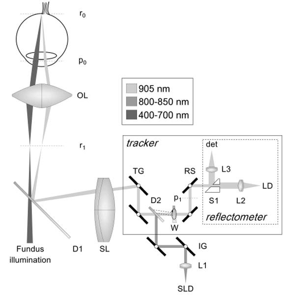
Optical schematic of TOCT (flattened for clarity). SLD: superluminescent diode, LD: laser diode, W: wedge, D1–2: dichroic beamsplitters, L1–3: fiber collimating lenses, TG: tracking galvano meter-driven mirrors, IG: OCT imaging galvanometer-driven mirrors, RS: resonant scanners, S1: split aperture, SL: scan lens, OL: ophthalmoscopic lens. Retinal and pupil conjugates shown (rx and px).
The retinal tracker was also significantly upgraded from previously reported systems. The opto-mechanical hardware of the new tracker was re-designed and made extremely compact for integration into the optical head of the Stratus OCT system. Figure 2 shows the clinical system, which externally looks identical to a Stratus OCT, and the compact optical head with integrated tracker (outer case removed). A wedge prism mounted in a rotary stage is now used to position the tracking beam on the retina. This allows the beam to be positioned on the favored target, the optic nerve head (bright lamina cribrosa), and easily switched between left and right eyes, or other targets such as large superior or inferior retinal arteries and veins. The dither scanner resonant frequency was increased from 8 kHz to 16 kHz by using smaller mirrors. Since the confocal aperture is defined by the size of the beam-splitting optic (S1 in Fig. 1) rather than the resonant scanner mirror clear apertures, this change was made with little change in confocality or reduction in signal intensity. One auxiliary benefit of this change for clinical operation is that the scanners are now essentially inaudible because the human ear usually has marginal sensitivity at 16 kHz. Also, the tracking beam wavelength was shifted further into the infrared to 905-nm (from 860 nm) to accommodate a broader OCT source bandwidth and the dichroic beamsplitter (D2) was also replaced to transmit this wavelength efficiently without clipping the OCT spectrum.
Fig. 2.
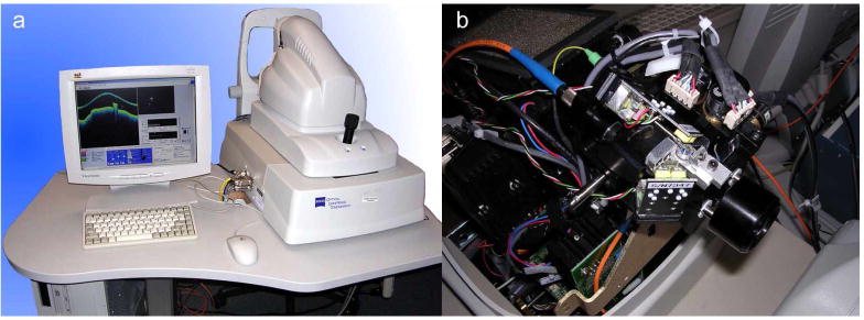
Photograph of TOCT3 system (a). Photograph of optical head (viewed from the top) illustrating location of tracker optics (b).
The system bandwidth was increased by upgraded the real-time DAP board and resonant scanners. The DAP board processor clock speed increased from 96 MHz to 400 MHz and the single channel signal acquisition speed increased from 16 kHz to 40 kHz (for closed-loop operation with throughput latency less than 1 cycle).
The retinal tracker and OCT scan acquisition software programs were unified into a single platform and run on a single computer. The acquisition software was written in LabVIEW (National Instruments Inc.) and C/C++ and the analysis software was written in LabVIEW and Matlab (Mathworks Inc.). In the previous-generation clinical TOCT system, separate software and two independent computers were used to control the tracking and imaging systems. Thus although a common beam path was used, the tracking and imaging beams essentially operated in independent coordinate frames from the standpoint of the control software. This necessitated a calibration methodology to assure that fixed OCT beam coordinates were used from one group of scans to the next. The system was more complex to operate. The new system is nearly as easy to operate as the standard Stratus system, and includes additional functionality (besides tracking) such as automatic blink detection and relock, scan pause and restart, and acquisition of OCT videos (rather than still frames). This enables operation with non-standard scans including groups of identical scans that can be co-added for increased image signal-to-noise ratio and raster scans for three-dimensional mapping of the macula or optic nerve head. The front panel of the new software platform is shown in Fig. 3.
Fig. 3.
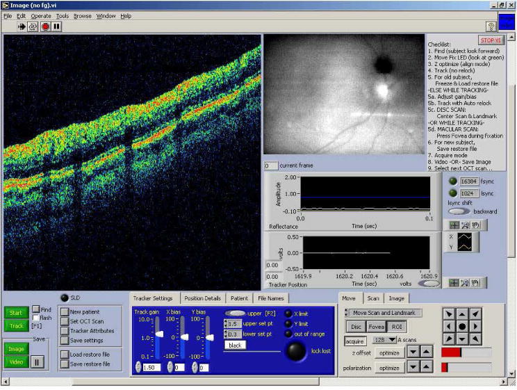
Front panel of the TOCT3 acquisition software.
Each subject in the studies was imaged with a standard set of scans. For many subjects, several non-standard scans were also collected. The standard scans consisted of three “fast” scans: fast optic disc, fast macular thickness map, and fast RNFL thickness. The “fast” scans differ from the normal OCT scans in that a number of scans with different orientation or multiple identical scans are acquired consecutively. The fast optic disc scan consists of six radial line scans centered on the optic disc in a spoke pattern and is designed to map optic nerve head topography. The fast macular thickness map is designed to map retinal nerve fiber layer (RNFL) and retina thickness with 6 radial line scans centered on the fovea. The fast RNFL thickness scan consists of three identical peripapillary scans (3.4-mm diameter circular scan centered on the disc).
The non-standard scans included high-density raster scans, circle group, line group, radial group and fast radial group. The “group” scans consist of a large number of identical scans acquired for the purpose of co-addition. The radial and fast radial groups differ in the order in which the scans are acquired. The radial group acquires a number of scans at one radial orientation and then moves to the next orientation. The fast radial group acquires a set of 6 radial lines (i.e., all radial orientations) and repeats a number of times.
Custom analysis software was used to process the scans. CZMI analysis software did not include the functionality required to process the non-standard scan types. The software coaligned the images with a cross-correlation algorithm. The algorithm computed the cross-correlation between A-scans from all the frames, calculated the peaks, and aligned each A-scan to the average peak position. The software also included the ability to flatten the final co-added image (or single images) to the bright layer that include RPE and choriocapillaris. The flattening algorithm used either a moving correlation between adjacent scans or a correlation between each A-scan and a fiducial A-scan to flatten. Flattening often distorts the true shape of the retina and does not enhance visualization and so was used sparingly in this paper. The analysis software also included capabilities to remove frames (for example during blinks when not tracking), add several sequences acquired at different times, create en-face images, and find the retinal surface (i.e., vitreo-retinal interface).
3. Results
To date, 10 subjects with normal eyes and 3 subjects with glaucomatous eyes have been scanned with the standard scan set. Herein we report the preliminary results of non-standard scans acquired from two normal subjects.
Figure 4 illustrates composite peripapillary scans generated by co-aligning and co-adding ~24 individual scans for the tracking (left) and non-tracking (right) cases. These scans are centered on the optic nerve head with 3.4-mm diameter and 512 A-scans (~21 μm per pixel). In each case a single scan (bottom) is included for comparison. In the non-tracking case, frames with blinks were removed from analysis. The topmost bands in these figures (Fig. 4a and b) are en-face profiles formed by summing each A-scan to create one horizontal line for each of 24 cross-sectional frames. With perfect registration, only vertical bands created from blood vessels should be visible. This is very nearly the case with tracking on the left. The bands show neither large line-to-line shifts that would result from rapid saccades nor a variation from first to last scan that would result from drift. Only small shifts of ~1 pixel are discernable from line to line. We surmise that this is due primarily to the small optical distortions caused by slow movement of the pupil during the 30 seconds required to complete these scans. However, without tracking, there are quite large variations in the vessel positions. The composite images (Fig. 4c and d) both show improvement in signal-to-noise ratio (SNR) and the same retinal layers can be seen in both images. The image SNR metric was calculated as the peak value of each A-scan divided by the average of the first 50 pixels averaged over all A-scans. The SNR was 4.0 and 3.6 for tracking and non-tracking compared to theoretical maximum improvement for uncorrelated noise of . However, the fine features (especially blood vessels) are clearly visible with tracking, while they have become blurred by motion without tracking. The vertical lines indicate alignment of blood vessels between single and composite image with tracking. Without tracking, the vessel has shifted 4 pixels. In the non-tracking case, the cross-correlation algorithm produced alignment errors especially at the vessel edges because A-scans through blood vessels were cross-correlated with A-scans through adjacent tissue when eye movements caused variations in scanned position.
Fig. 4.
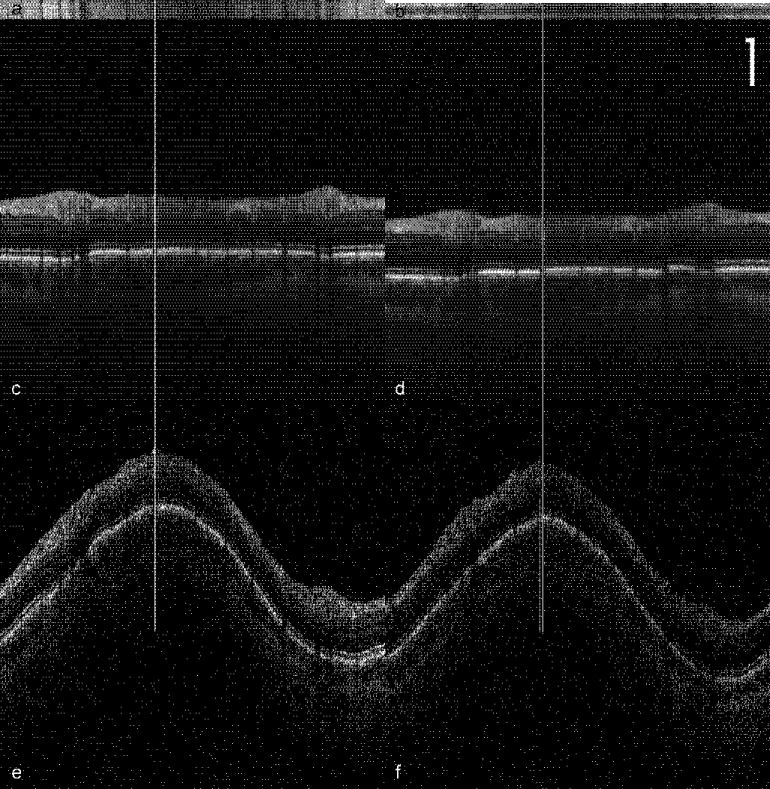
Peripapillary OCT scans comparing tracking (a,c,e) and non-tracking (b,d,f). 24 scans were collected sequentially. (a,b) Each horizontal line of the en-face profile was created by summing the A-scans in the frame. (c,d) Composite image created by aligning and co-adding all the frames. (e,f) Single frames used to create the composite images in c and d. Vertical lines show location of a blood vessel in single and composite images. Scale bar = 250 μm.
To determine quantitative tracking accuracy, we examined the blood vessel shadow in the center of the frames (indicated by the vertical lines in Fig. 4) made in the bright choriocapillaris layer. We averaged several (5–10) horizontal lines in this layer and plotted the profiles for each of the 24 frames that made up the sequence. The results are plotted in Fig. 5. The standard deviation in blood vessel shadow edge was 0.5 pixels (10.4 μm or 0.036 deg) with tracking and 2.4 pixels (50.1 μm or 0.17 deg) without tracking.
Fig. 5.
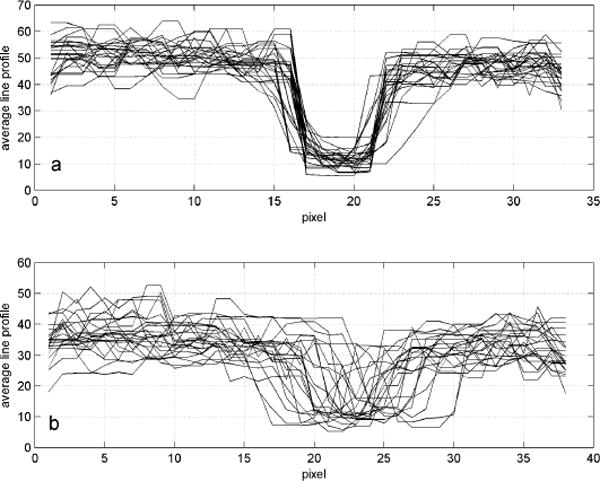
Averaged line profiles of the region of a blood vessel for each frame used to create the composite image in Fig. 4c and 4d for (a) tracking and (b) non-tracking. Each pixel is ~21 μm.
To test the repeatibility of tracking, two sets of peripapillary composite images were captured over the course of approximately 2 hours (2:01 with tracking and 1:48 without tracking). These resulting en-face images and the summed composites for tracking and non-tracking are shown in Fig. 6. The tracking case (left) shows high fidelity in returning to the original coordinates, as illustrated by the alignment of the vertical bands in the en-face representation. The composite image with tracking again shows a large number of fine retinal details. Some alignment errors at the vessel margins occurred during processing of the tracking images, but they are small in number and occur where the OCT signal is weaker. In contrast, the non-tracking case (right) shows bands in the en-face image that are irregular and misaligned between the two measurements. This is due to a significant inter-session shift in the center coordinate of the peripapillary scans groups without tracking. The composite images for the non-tracking case contain many alignment errors and the fine features are completely blurred by motion.
Fig. 6.
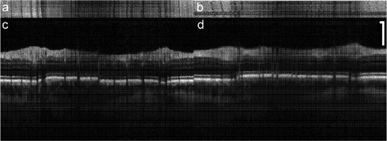
Repeatibility of tracking. En-face (a,b) and composite (c,d) images created by co-adding 48 frames from two sets of scans taken 2 hours apart. Scale bar = 250 μm.
Line group scans from macula to disc are shown in Fig. 7. For these groups, 24 8-mm scans were performed in succession with 512 A-scans each (15.6 μm per pixel). In contrast to the single scan, the nerve fiber layer is sharply defined, and the external limiting membrane is also discernable. Again, the retinal layers are visible without tracking but fine features are blurred. With tracking, small blood vessels, the foveal reflex, and lamina cribrosa are all clearly visible. A magnified image of the fovea with tracking (taken from Fig. 7b) with labeled retinal layers is shown in Fig. 8. We note that in the composite images acquired with tracking, all the retinal layers normally only seen with high resolution systems [5], including the external limiting membrane (ELM) and the retinal pigment epithelium (RPE), are clearly resolved.
Fig. 7.
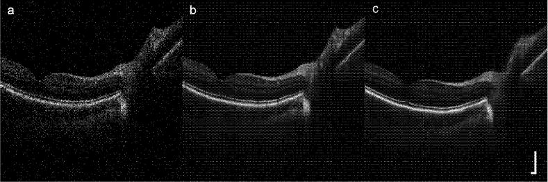
Line scan through disc and fovea: (a) single image, (b) composite image (24 co-added frames) with tracking, and (c) composite image without tracking. Scale bar = 250 μm.
Fig. 8.
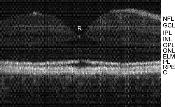
Magnified TOCT composite (24 frame) image of fovea with labeled retinal layers. Small retinal vessels are also identified with circles. NFL: nerve fiber layers, GCL: ganglion cell layer, IPL: inner plexiform layer, INL: inner nuclear layer, OPL: outer plexiform layer, ONL: outer nuclear layer, ELM: external limiting membrane, PL: photoreceptor layer (interface between inner and outer segments delineated by bright reflection), RPE: retinal pigment epithelium, C: choriocapillaris and choroid.
Finally, we present videos from the first 3D data cubes generated from successive cross-sectional raster scans obtained with the Stratus-based TOCT. The videos show cross-sectional and en-face “fly-throughs” of the data obtained from the macula and optic disc. Figure 9 is a 4×4×2 mm raster scan (128×128×512 pixels) through the fovea acquired in approximately 41 seconds. Each transverse pixel is 31 μm. This type of data cube would be nearly impossible to acquire in a time-domain system without retinal tracking. The first video segment shows a cross-sectional fly-through. On the left side the en-face view is constructed by summing the image cube along the A-scan dimension (z). On the right side, each cross-sectional B-scan in the macula is sequentially displayed and its position in the en-face image indicated by the white horizontal line on the left. Note the thin nerve-fiber layer, the absence of external retinal layers (i.e., fovea pit) and the larger retinal vessel (at the bottom) in this cross-sectional sequence. The second video segment shows an en-face fly-through. The right side show a fixed eross-sertional section through the foveal pit The left side shows a fly-though in depth Note the visualization of structures, including retinal and choroidal vasculature, not seen in the cross-sectional view.
Fig. 9.
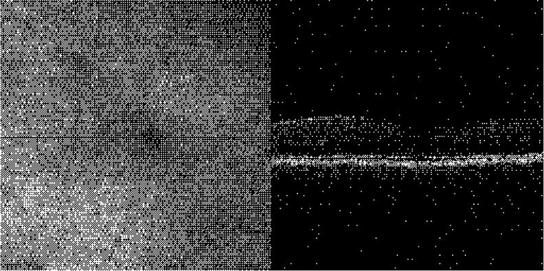
(3.5 Mb) En face (left) and cross-sectional scans (right) through the macular region Fovea is dark region in the center on the right and the region without overlying nerve fiber layer on the right.
Figure. 10 shows a higher density scan through the optic nerve head acquired in 164 seconds The auto-relock algorithm automatically paused OCT scanning during blinks and repositioned and re-locked the retinal tracking during this long duration The image cube is 4×4×2 mm (256×256×512 pixels) and each transverse pixel is 15 6 (μm A cross-sectional fly through is presented in Fig. 10 The left side is the en-face representation, while a video of sequentially acquired B-scans is displayed on the right The optic disc of the en-face image appears smooth and distortion-free with no apparent motion artifacts (The en-face fly-through of the disc did not reveal further information and is not presented.)
Fig. 10.
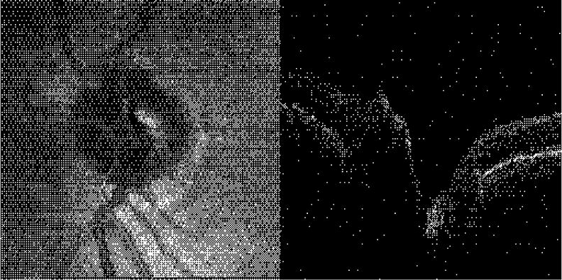
(1.7 Mb) En face (left) and cross-sectional scans, (right) through the oplic nerve head.
4. Discussion
The results presented above show that if eye motion and other factors related to human interface can be controlled, the high performance and functionality necessary for early detection, characterization, and monitoring of retinal diseases can be achieved even with conventional time-domain OCT. High density 3D OCT retinal videos, created by other investigators with re-ordered scan sequences [1] or high-speed Fourier domain techniques [4, 5], can only be further enhanced with image stabilization. Composite images generated without tracking show increased signal-to-noise ratio and a clear delineation of retinal layers, which have low gradients in the transverse direction. For example, the photoreceptor layer thickness varies less than 10% across several mm in Figs. 7b and c. However, any feature smaller than several pixels is not resolved in these composite images. The main features of the tracking composite image are the improvement in transverse alignment leading to clear vessel shadows, resolved vessel lumens, higher contrast layer boundaries, persistent fine structure, and sharper choroidal detail and contrast. The persistence of speckle suggests the RMS stabilization is significantly smaller than the diffraction-limited OCT beam diameter of ~20 μm. The appearance of the composite images, though with lower axial resolution, bear increasing resemblance to high scan density, high resolution images taken by other investigators with research systems [4, 5]. It is interesting to consider what imaging benefits tracking would confer on high-resolution composite images.
In a previous publication that described our work with a retinal tracker integrated into a second-generation OCT system with lower transverse resolution [7], we hypothesized that if the transverse resolution was improved, the registration accuracy (measured using OCT images) for the non-tracking case, governed by the fixational ability of the subject, would increase, while that for tracking would decrease until the pixel size was lower than the ultimate limit of the tracking hardware. In the previous work, the registration accuracy for an especially good fixator was 0.5 and 1.6 pixels (30 and 97 μm), with and without tracking, respectively. For the same subject in this study, the registration accuracy was 0.5 and 2.4 pixels (10 and 50 μm), with and without tracking, respectively. This suggests we have not yet reached the limit of tracking accuracy for OCT imaging at the present resolution, limited by detector noise, analog input and output voltage signal resolution, and other factors that determine galvanometer positional accuracy. Measurement of RMS position variation during tracking is ~5 μm.
The tracking system corrects only rotational eye movements that cause transverse shifts in retinal images. Some of the stabilization errors that remain can be attributed to torsional eye motion or ocular geometry effects, which can be up to 0.2 deg, depending on the eccentricity of the region-of-interest scanned. This motion would manifest as collective shifts in the position of the blood vessels bands in the en-face images of the peripapillary scans. (Transverse movements will cause the vessel bands to shift with respect to each other, depending upon the orientation of the vessel with the direction of the saccade). These eye movements could also be corrected with real-time rotation-correction algorithms, since the angle of rotation can be obtained from the tracking target and its trajectory. For high resolution OCT systems, such additional corrections may become more important.
Future clinical work will include quantification of RNFL measurement accuracy for early diagnosis of glaucoma and further characterization of tracking repeatability for various clinical longitudinal studies and other non-standard imaging protocols. Future systems will integrate the retinal tracker and high resolution and high-speed (i.e., Fourier domain) OCT instruments.
Acknowledgments
This work was supported in part by NTH Grants EY013036 and RO1-EY013178-5P30-EY008098, The Eye and Ear Foundation (Pittsburgh) and an unrestricted grant from Research to Prevent Blindness, Inc. Carl Zeiss Mediteec Inc. provided a Stratus OCT system for the investigation.
References and links
- 1.Podoleanu A, Rogers JA, Jackson DA, Dunne S. Three dimensional OCT images from retina and skin. Opt Express. 2000;7:292–298. doi: 10.1364/oe.7.000292. http://www.opticsexpress.org/abstract.cfrn?URI=OPEX-7-9-292. [DOI] [PubMed] [Google Scholar]
- 2.Fereher AF, Hitzenberger CK, Kamp G, El-Zaiat SY. Measurement of intraocular distances by backscattering spectral interferometry. Opt Commun. 1995;117:43–48. [Google Scholar]
- 3.Wojtkowski M, Leitgeb R, Kowalczyk A, Bajraszewski T, Fercher AF. In vivo hurman retinal imaging by Fourier domain optical coherence tomography. J Biomedical Opt. 2002;7:457–463. doi: 10.1117/1.1482379. [DOI] [PubMed] [Google Scholar]
- 4.Nassif NA, Cense B, Park BH, Pierce MC, Yun SH, Bouma BE, Tearney GJ, Chen TC, de Boer JF. In vivo high-resolution video-rate spectral-domain optical coherence tomography of the human retina and optic nerve. Opt Express. 2004;12:367–376. doi: 10.1364/opex.12.000367. http://www.opticsexpress.org/abstract.cfm?URI–OPEX-12-3-367. [DOI] [PubMed] [Google Scholar]
- 5.Cense B, Nassif NA, Chen TC, Pierce MC, Yun S, Park BH, Bouma BE, Tearney GJ, de Boer JF. Ultrahigh-resoluti on high-speed retinal imaging using spectral-domain optical coherence tomography. Opt Express. 2004;12:2435–2447. doi: 10.1364/opex.12.002435. http://www.opticsexpress.org/abstract.cfm?URI=OPEX-12-11-2435. [DOI] [PubMed] [Google Scholar]
- 6.Ferguson RD, Hammer DX, Paunescu LA, Beaton S, Schuman JS. Tracking Optical Coherence Tomography. Opt Lett. 2004;29:2139–2141. doi: 10.1364/ol.29.002139. [DOI] [PMC free article] [PubMed] [Google Scholar]
- 7.Hammer Daniel X, Ferguson R Daniel, Magill John C, Adelina Paunescu Lelia, Beaton Siobahn, Ishikawa Hiroshi, Wollstein Gadi, Schuman Joel S. An Active Retinal Tracker for Clinical Optical Coherence Tomography Systems. J Biomedical Opt. 2005;10:024038. doi: 10.1117/1.1896967. [DOI] [PMC free article] [PubMed] [Google Scholar]
- 8.Hammer DX, Ferguson RD, Magill JC, White MA, Eisner AE, Webb RH. Image stabilization for scanning laser ophthalmoscopy. Opt Express. 2002;10:1542–1549. doi: 10.1364/oe.10.001542. http://www.opticsexpress.org/abstract.cfm?URI=OPEX-10-26-1542. [DOI] [PubMed] [Google Scholar]
- 9.Hammer DX, Ferguson RD, Magill JC, White MA, Eisner AE, Webb RH. Compact scanning laser ophthalmoscope with high speed retinal tracker. Appl Opt. 2003;42:4621–4632. doi: 10.1364/ao.42.004621. [DOI] [PubMed] [Google Scholar]
- 10.Ferguson RD. Servo Tracking System Utilizing phase-Sensitive Detection of Reflectance Variation. U S Patent #5,767,941 and #5,943,115 [Google Scholar]
- 11.Ferguson RD, Hammer DX, Eisner AE, Webb RH, Burns SA, Weiter JJ. Wide-field retinal hemodynamic imaging with the tracking scanning laser ophthalmoscope. Opt Express. 2004;12:5198–5208. doi: 10.1364/opex.12.005198. http://www.opticsexpress.org/abstract.cfm?URI=OPEX-12-21-5198. [DOI] [PubMed] [Google Scholar]


