

Abstract
Quantum state preparation of mesoscopic objects is a powerful playground for the elucidation of many physical principles. The field of cavity optomechanics aims to create these states through laser cooling and by minimizing state decoherence. Here we demonstrate simultaneous optical trapping and rotation of a birefringent microparticle in vacuum using a circularly polarized trapping laser beam—a microgyroscope. We show stable rotation rates up to 5 MHz. Coupling between the rotational and translational degrees of freedom of the trapped microgyroscope leads to the observation of positional stabilization in effect cooling the particle to 40 K. We attribute this cooling to the interaction between the gyroscopic directional stabilization and the optical trapping field.
 Quantum state preparation of mesoscopic objects is a powerful tool for the study of physics at the limits. Here, Arita et al. realise the optical trapping of a microgyroscope rotating at MHz rates in vacuum where the coupling between the rotational and translational motion cools the particle to 40 K.
Exquisite control over all the degrees of freedom of a macroscopic object is a precursor for exploring the transitions between the classical and quantum world. With this remit, the complete optical control over an isolated nano- or microscopic particle in vacuum is an exciting testbed for such studies, crucially minimizing decoherence1. Such a system promises precision measurements of weak forces at the quantum limit solely constrained by the homogeneous linewidth of the ground state of the mechanical oscillator2,3,4,5,6. This raises the prospect of quantum entanglement between the incident light field and the mechanical modes of a trapped oscillator6,7,8,9,10, for example. Furthermore, there is the potential for exploring the predictions of the Casimir force and quantum friction11,12 if such a particle can be set into rotation at sufficiently high angular velocities and controllably positioned next to a surface.
Here, we present a trapped, levitated rotating microparticle confined in an optical potential, rendering it well isolated from the thermal environment. Previous studies have shown that microparticles may be held in vacuum and then cooled to millikelvin temperatures using ‘active’ feedback schemes13,14. However, by including the rotational degrees of freedom15,16, we can consider cooling in the absence of any ‘active’ feedback, in contrast to previous experiments13,14. This approach opens up a powerful route to explore the fascinating predictions of quantum friction11,12, which may ultimately have a profound impact upon nanoscale devices. We demonstrate controlled rotation of a single trapped microparticle at background gas pressures ranging from 105 Pa (atmospheric) down to 10−1 Pa, where we recorded the maximum rotation rates of up to frot=5 MHz (increasing to 10 MHz for short durations of time). We observe coupling between the rotational and translational degrees of freedom of the trapped object that leads to particle effective-cooling to 40 K in the absence of any ‘active’ cooling method. This rotating particle may be considered as a microscopic gyroscope.
Results
AM transfer
When a birefringent uniaxial crystal, such as vaterite (see Methods for details), is trapped in a linearly polarized (LP) beam, the optical axis of the crystal will align with the electric field, which is perpendicular to the propagation direction of the beam. In contrast to LP light, circularly polarized (CP) light incident on a birefringent particle will induce a rotation of the particle17,18. This is caused by the transfer of spin AM from the beam to the microparticle. Indeed, the birefringent particle induces a phase retardation between the ordinary and extraordinary components of the beam reversing the photon AM (±ħ per photon) of the incident CP light. If the particle acts as a half-wave (λ/2) plate, the maximum spin AM will be transferred to the particle, with a spin AM change of 2 ħ per photon. Considering the conservation of energy and AM in this process, a frequency shift arises owing to the angular Doppler effect as (ω1−ω2)/2=Ωrot=2πfrot, where ω1 and ω2 are the angular frequencies of the light before and after passing through the particle, repectively, and Ωrot is the angular rotation frequency of the particle19. As a result, we observe optical beating at 2Ωrot when the particle rotates at Ωrot.
Power spectra
Figure 1 shows typical power spectral density (PSD) signals (measured by PDi=1 as defined in the Methods section) of the scattered light from a trapped particle. In Fig. 1a, the particle experiences a rotational trapping torque owing to an LP light field. Figure 1b, c show the cases when the particle is trapped by a CP light field at pressures of 1 kPa and 15.1 Pa, respectively. In the following, we consider the PSD defined using the Fourier transform of the signal measured by PDi and denoted as S(f). The PSD measured at low pressures exhibits resonance peaks at the translational oscillation frequencies of fxy and fz corresponding to the periodic motion of the particle in the lateral x–y and axial z directions. Figure 1c shows the oscillation frequencies of fxy at 660 Hz and fz at 420 Hz for this specific particle. Further, the PSD shows an optical beating at 2frot when the particle rotates at a rate of frot (Fig. 1b, c). In practice, frot is also detected because of the variation in the photodiode signal induced by small optical asymmetry of the particle. We remark that higher harmonics of the fundamental rotation frequency of frot and translational oscillation frequencies of fxy and fz are also observed in the PSD signal (Fig. 1c).
Figure 1. PSD signals of the scattered light from a trapped particle.

(a) Optical trapping by an LP light field (that is, no induced rotation) at 1 kPa. (b) Optical trapping by CP light at 1 kPa showing an optical beating frequency at 2frot together with frot. (c) PSD at 15.1 Pa showing translational (fxy, fz) and rotational (frot) frequencies of a trapped particle.
Rotation rate
A trapped spinning birefringent microparticle will reach a terminal rotation frequency owing to the Stokes drag torque, dependent upon particle size and gas viscosity. The effective gas viscosity, μe experienced by a spherical microparticle can be empirically estimated as20
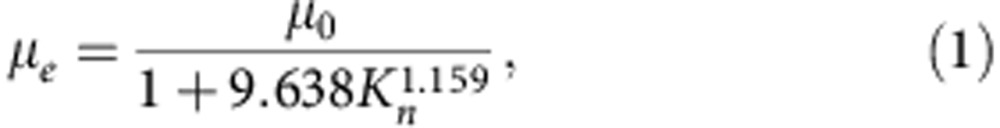 |
where μ0 is the viscosity coefficient at the reference pressure P0, and Kn=λa/d is the Knudsen number. Here  is the mean free path (mfp) of air molecules at a pressure Pa relative to the mfp of λ0 at the reference pressure P0, and d is the diameter of the particle. As the pressure decreases, the mfp of the surrounding gas molecules becomes comparable to the particle diameter implying Kn≈1. This marks a transition to a regime where radiometric forces are negligible and the viscosity becomes proportional to the pressure. Figure 2 shows the rotation rate frot of a trapped particle as a function of pressure measured by observation of the PSD (Fig. 2 inset). An initial rotation rate of 110 Hz is recorded at atmospheric pressure, which increases to a stable rotation rate of 5 MHz for a pressure of 0.1 Pa. Decreasing the pressure further can lead to rotation rates of up to 10 MHz, although, at such rates, the particle is lost in a short period of time. We remark that this represents, to date, the largest measured rotation rate for a ‘man-made’ object21. The model in Fig. 2 is calculated using equation (1), implying a pressure-dependent Stokes rotational drag coefficient. The discrepancy between the model and experimental values at pressures below 10 Pa could be attributed to particle instability induced by heat because of light absorption22,23, while the low pressure particle loss might be due to the large inertial forces experienced by the particle at high rotation rates.
Figure 2. Rotation rate of a trapped particle at different gas pressures.

The model fits to the experimental data for 0≤Kn≤880. Inset shows the PSD at a rotation rate of 2.45 MHz at a pressure of 1 Pa.
Parametric coupling
An optically trapped and simultaneously rotated particle in vacuum offers original perspectives on particle dynamics. It is of particular interest to study the dynamics when the rotation frequency frot coincides with the oscillation frequency fxy of the trapped particle. A series of power spectra tracking the major peaks of the PSD at each pressure from 1 kPa to 100 Pa are shown in Fig. 3a. The rotation frequency signal exhibits kinks at frot≈fxy (at 380 Pa) and at frot≈2fxy (at 210 Pa). Figure 3b shows the amplitude of the PSD peak at the oscillation frequency fxy as the rotation frequency of the trapped particle changes. We observe an enhanced signal at frot≈fxy corresponding to a driven resonance. A second resonance occurs when frot≈2fxy, suggesting a parametric resonance24. The coupling between the oscillatory motion and rotational motion of the particle can also be observed in Fig. 3c,d. The photodiode signal (PD1) in time domain measured at a pressure of 13.6 Pa exhibits fine rotational modulation (Fig. 3c inset), which is further modulated by slower frequency components (Fig. 3c). The power spectrum of these modulations reveals the rotation frequency frot accompanied with sidebands separated by fxy (Fig. 3d).
Figure 3. Coupling of the rotational and translational motion of a trapped particle.

(a) Major peaks of the PSD signal around the resonance frequency at frot≈fxy. In red are frequency peaks associated with rotation and in blue the ones associated with translational oscillations. (b) Resonances found at fxy and 2fxy when frot scans across these frequencies. (c) Photodiode signal in time domain showing mixed frequency components at 13.6 Pa. Inset shows the expanded view of the selected region. (d) Fourier transform of the time-domain signal (Fig. 3c) showing the rotation frequency of frot with sidebands separated by fxy. (e) Simulated PSD signal at a high rotation frequency showing the appearance of sidebands and their harmonics due to the modulation of the trapping frequency. (f) Simulated PSD signal for two different gas viscosities corresponding to the resonant (blue) and non-resonant (red) cases.
We approximatively model the dynamics of a birefringent particle in an optical potential and subject to position- and orientation-dependent torque. To simplify the system while maintaining its main optical properties, we consider the induced polarization of an anisotropic dipole25 corrected for the anisotropic radiative process26. The optical forces and torques are calculated by generalizing the cycle-averaged Lorentz force27 and torque28 to account for the anisotropy owing to birefringence. Optically, the spherical aberration introduced by the total internal reflection at the glass–vacuum interface is taken into account by using angular spectral decomposition of the incident beam29 (Supplementary Note 1). We remark that at the levitated equilibrium position of the particle, the trapping forces can be approximated with an optical harmonic potential originating from a CP Gaussian beam. In the simulations, we use this potential and adjust the beam parameters such that the transversal trap oscillation is ≈660 Hz for a vaterite microparticle whose diameter is 4.40 μm. The rotation of the microparticle is modelled by the Euler equations for a solid sphere with a slight asymmetry of 0.1% in one of its moments of inertia (Supplementary Note 2). This mechanical asymmetry introduces a principal momentum axis that does not overlap with the optical axis of the particle.
For these mechanically anisotropic particles, the Brownian stochastic torques are introduced in the rotational Langevin equation30, which are generalized to include an external torque31 and contributions from the Euler equations in the body frame of reference (Supplementary Note 3). Finally, the detection is simulated by Fourier transforming the dipole polarization intensity along a fixed direction. This Fourier transform corresponds to the PSD signal observed. Figure 3e shows the simulated PSD of a rotating dipole particle oscillating periodically in the beam. The central resonance corresponds to the polarization change due to rotation, whereas the multiple sidebands correspond to periodic variations of the electric field strength as the particle oscillates in the trap. These simulations indicate that the coupling behaviour observed in Fig. 3b occurs when the rotational frequency is resonant with the fundamental and the second harmonic of the translational frequency corresponding, respectively, to a driven oscillator resonance and a parametric resonance. Indeed, parametric resonance occurs as the trap stiffness varies slightly for different orientations of the particle, whereas this orientation changes as the particle rotates. Figure 3f shows the enhancement of the PSD signal at the transversal oscillation frequency fxy peak as the rotational frequency becomes resonant.
Cooling
Our trapped microparticle has three rotational and three translational degrees of freedom. These are coupled due to the optical anisotropy of the microparticle, which can be seen in Fig. 3b,d–f. We now progress to investigate the impact of the rotation rate on the rotational degrees of freedom. In this case, we observe the effective cooling of microparticles through rotation in the absence of any ‘active’ feedback method. Akin to the motion of a spinning top, a rotating body offers inertial stiffness, which prevents the body from drifting from its desired orientation. Here the high rotation rates achieved using the microgyroscope lead to the intrinsic stabilization of its axis of rotations with respect to perturbations. This effect is similar to stabilizing the rigid-body dynamics of an oval football32 or spin-stabilized satellite33. Our numerical simulations indicate that for increasing rotation rate, the distribution width of the fixed-frame transversal angular velocities νx and νy decrease (Fig. 4a,b). This effect can be seen as a cooling effect on the two rotational degrees of freedom of the microgyroscope at the expense of the third rotational degree of freedom around which the rotation occurs, supporting our conclusions from the experimental data. Owing to rotational–translational coupling mentioned above, this rotational stabilization also enables cooling for all the three translational motion degrees of freedom. More specifically, when the laser is switched on, it heats the transversal motion of the particle due to the stochastic fluctuation of the microparticle orientation. As the particle rotates faster, its orientation is stabilized by the gyroscopic effect and as such the particle experiences relative cooling.
Figure 4. Effective cooling of the microgyroscope as a function of the rotation rate.

(a) Simulated distribution of the angular velocity, νx around a transversal axis and (b) around the longitudinal axis, νz for different average rotation rates. The bimodal distribution is owing to particle precession at low rotation rates. (c) Position distributions of a trapped particle at different rotation rates. (d) Particle effective temperature, Teff at different pressures determined by the equipartition method. (e) PSD signals of the scattered light from a trapped particle with and without rotation. (f) Effective temperatures, Teff determined for both a rotating and a non-rotating particle using the PSD signals.
Discussion
To investigate the cooling effect in more detail, we study the integral of the PSD signal S(f). This quantity is proportional to the mean square displacement of the particle  x2
x2 and depends only upon trap strength and temperature34,35. That is
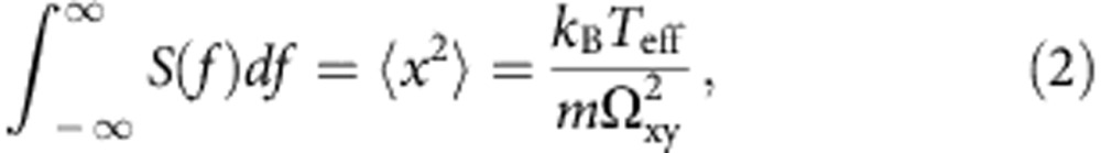 |
where kB is the Boltzmann’s constant, Teff defines the effective temperature, m is the mass of the particle,  the natural oscillation frequency in absence of damping and κ denotes the trap stiffness (Supplementary Fig. S1 and Supplementary Note 3). A similar relationship can be obtained when considering the axial z direction. Equation (2) can be used in different ways to determine the effective temperature of the microparticle in the optical field. In this paper, we use three approaches. The first approach is based on the equipartition theorem illustrated in Fig. 4c that compares the distribution of particle positions in a lateral direction x for different rotation rates at frot=1 kHz and at frot=78 kHz. The Teff of the particle is calibrated at room temperature by associating with the variance of the position distribution of the trapped particle held at atmospheric pressure. Figure 4d shows the Teff of the trapped particle at different rotation rates, where we observe that the effective temperature of the particle reaches a minimum of 40 K at frot=78 kHz. Similar cooling behaviour can be observed in the axial z direction (Supplementary Fig. S2).
The effective temperature can also be determined using the power spectral density of the scattered light field either through its integral (2) or by measuring its low frequency response (Supplementary Fig. S3 and Supplementary Note 3). Figure 4e compares the PSD signals for the cases of both a rotating and a non-rotating particle. The integral of this PSD signal is proportional to the centre-of-mass positional variance and is thus related directly to the particle effective temperature in a trapping potential. We monitor Teff as a function of pressure for a rotating and a non-rotating particle (Fig. 4f). For the non-rotating particle, we do not observe any cooling effect. Additionally, the trap becomes unstable at 1 kPa and the particle is lost from the trap typically at 300 Pa, corresponding to the frot≈fxy resonance. Applying an optical torque stabilizes the particle and enables us to maintain the trapped particle through this resonant transition. The PSD signal shows that Teff increases up to the resonance point (frot≈fxy). At higher rotation frequencies, it is seen to decrease, reaching a minimum value of 40 K at a rotation frequency of frot=78 kHz corresponding to a background pressure of 4.2 Pa. Altogether, all three methods determining the temperature lead to the observation of effective cooling of the centre-of-gravity motion of the particle. In future work, we will explore the origin of the particle instability at high rotation rates.
In conclusion, the trapped microgyroscope presents a powerful and original route to explore new directions in cavity optomechanics and is a major step towards measuring rotational quantum frictional forces in vacuum.
Methods
Experimental set-up
The experimental system (Fig. 5) comprises a miniature vacuum chamber (VC), which has two optical glass windows. Light is focused in the VC using a high numerical aperture microscope objective (MO, Nikon Ltd., E Plan × 100, NA=1.25). A piezo electric transducer (PZT) is affixed to the chamber to load the levitation air/vacuum trap with microparticles from the glass substrate18. Rotation of microparticles is achieved by trapping a birefringent spherical vaterite crystal (4.40 μm in diameter) with a CP light field at an optical power of 25 mW (measured at the back aperture of the MO). The polarization state of the scattered light from the trapped particle is recorded by fast photodiodes (PDi, i=1–3) to determine the particle dynamics.
Figure 5. Schematic of the experimental set-up used for the trapping and rotation of a birefringent microparticle in vacuum.

Labels denote the continuous wave (CW), half-wave plate (λ/2), polarizing beam splitter (PBS), lenses (L), mirror (M), dichroic filters (DF), quarter-wave plate (λ/4), microscope objective (MO), circularly polarized trapping laser beam (CP), condenser (CD), 50/50 beam splitter cube (BS), photodiodes (PDi), nanosecond laser (NS), fast imaging device (CMOS), digital storage oscilloscope (DSO), computer (PC), vacuum chamber (VC), piezo electric transducer (PZT), vacuum gauge (VG), vacuum pump (VP), rotational frequency of a trapped particle (frot) and translational oscillation frequencies (fxy, fz) of a trapped particle in lateral and axial directions.
Beam preparation
The trapping laser beam (IPG Laser GmbH, YLM-5-1070-LP: continuous wave (CW), wavelength 1,070 nm, power 5 W) propagates through a half-wave plate (λ/2) followed by a polarizing beam splitter cube (PBS). This enables the control of the optical output power as well as the generation of a LP light field. The beam is collimated and expanded to overfill the back aperture of the MO in order to obtain a diffraction-limited focal spot. A quarter-wave plate (λ/4) is placed immediately before the MO to create a CP light field.
Vacuum chamber
The VC is made of stainless steel with a volume of 27.7 μl. This has two optical glass windows (Harvard Apparatus Ltd., CS-8R: 8 mm in diameter, 150 μm in thickness) compatible with the microscope objective used. An annular piezo electric transducer (PZT, APC International Ltd., Cat. no.70-2221) affixed to the chamber is operated at 340 kHz to detach the microparticles from the lower glass window to load the optical trap in air/vacuum.
Birefringent crystals
We synthesize vaterite crystals for our experiments18. Vaterite is a positive uniaxial birefringent material with a spherical morphology. Figure 6 shows the images of vaterite crystals acquired by a scanning electron microscope (SEM) at different scales. The obtained vaterite particles are monodisperse with a mean diameter of 4.40±0.05 μm (2σ) and a surface roughness of 27.6 nm (2σ).
Figure 6. SEM images of vaterite crystals.

(a) A selection of monodisperse particles. (b) A closer look at Fig. 6a. (c) A single vaterite crystal with a near-perfect sphericity. (d) A closer look at Fig. 6c showing the surface roughness of the particle. Scale bars, 10 μm in (a), 5 μm in (b), 2 μm in (c) and 500 nm in (d).
Detection scheme
Once a single vaterite sphere is trapped and rotated at atmospheric pressure, the chamber pressure is gradually reduced to 10−1 Pa. The transmitted light through the trapped particle is collected using a condenser lens (CD, Nikon Ltd., E plan × 10, NA=0.25 in air) and directed on fast photodiodes (PDi, Thorlabs Inc., DET10C, InGaAs) to record the particle dynamics. PD2 and PD3 measure the right and left CP components of the scattered light, which are used for the determination of the optical torque transfered to the particle18. A fast CMOS camera (Mikrotron GmbH, EoSens: >10 k fps) synchronized with nanosecond laser pulses (NS, Elforlight Ltd., SPOT: pulse width ≤1 ns) acts as a stroboscopic illumination to track the translational centre-of-mass motion of a trapped particle in x, y and z directions.
Author contributions
All authors contributed to the development and planning of the project, interpretation and discussion of the data and the writing of the manuscript. Y.A. performed the experiments and data analysis, and M.M. the theory and numerical modelling. K.D. initiated and supervised the project.
Additional information
How to cite this article: Arita, Y. et al. Laser-induced rotation and cooling of a trapped microgyroscope in vacuum. Nat. Commun. 4:2374 doi: 10.1038/ncomms3374 (2013).
Supplementary Material
Supplementary Figures S1-S3 and Supplementary Notes 1-3
Acknowledgments
We thank the UK Engineering and Physical Sciences Research Council (EPSRC grant numbers: EP/J01771X/1 and EP/G061688/1) for funding. K.D. acknowledges the support from a Royal Society Wolfson-Merit Award. We thank A. Di Falco for the SEM images of vaterite crystals and M. Ross for the development of the high power PZT controller.
References
- Julsgaard B., Kozhekin A. & Polzik E. S. Experimental long-lived entanglement of two macroscopic objects. Nature 413, 400–403 (2001). [DOI] [PubMed] [Google Scholar]
- Wilson-Rae I., Nooshi N., Zwerger W. & Kippenberg T. J. Theory of ground state cooling of a mechanical oscillator using dynamical backaction. Phys. Rev. Lett. 99, 093901 (2007). [DOI] [PubMed] [Google Scholar]
- Groblacher S. et al. Demonstration of an ultracold micro-optomechanical oscillator in a cryogenic cavity. Nat. Phys. 5, 485–488 (2009). [Google Scholar]
- Barker P. F. Doppler cooling a microsphere. Phys. Rev. Lett. 105, 073002 (2010). [DOI] [PubMed] [Google Scholar]
- O'Connell A. D. et al. Quantum ground state and single-phonon control of a mechanical resonator. Nature 464, 697–703 (2010). [DOI] [PubMed] [Google Scholar]
- Chan J. et al. Laser cooling of a nanomechanical oscillator into its quantum ground state. Nature 478, 89–92 (2011). [DOI] [PubMed] [Google Scholar]
- Kippenberg T. J. & Vahala K. J. Cavity optomechanics: back-action at the mesoscale. Science 321, 1172–1176 (2008). [DOI] [PubMed] [Google Scholar]
- Jost J. D. et al. Entangled mechanical oscillators. Nature 459, 683–684 (2009). [DOI] [PubMed] [Google Scholar]
- Chang D. E. et al. Cavity opto-mechanics using an optically levitated nanosphere. Proc. Natl Acad. Sci. USA 107, 1005–1010 (2010). [DOI] [PMC free article] [PubMed] [Google Scholar]
- Teufel J. D. et al. Sideband cooling of micromechanical motion to the quantum ground state. Nature 475, 359–363 (2011). [DOI] [PubMed] [Google Scholar]
- Manjavacas A. & De Abajo F. J. G. Vacuum friction in rotating particles. Phys. Rev. Lett. 105, 113601 (2010). [DOI] [PubMed] [Google Scholar]
- Zhao R. K., Manjavacas A., De Abajo F. J. G. & Pendry J. B. Rotational quantum friction. Phys. Rev. Lett. 109, 123604 (2012). [DOI] [PubMed] [Google Scholar]
- Li T. C., Kheifets S. & Raizen M. G. Millikelvin cooling of an optically trapped microsphere in vacuum. Nat. Phys. 7, 527–530 (2011). [Google Scholar]
- Gieseler J., Deutsch B., Quidant R. & Novotny L. Subkelvin parametric feedback cooling of a laser-trapped nanoparticle. Phys. Rev. Lett. 109, 103603 (2012). [DOI] [PubMed] [Google Scholar]
- Romero-Isart O., Juan M. L., Quidant R. & Cirac J. I. Toward quantum superposition of living organisms. New J. Phys. 12, 033015 (2010). [Google Scholar]
- Bhattacharya M. & Meystre P. Using a Laguerre-Gaussian beam to trap and cool the rotational motion of a mirror. Phys. Rev. Lett. 99, 153603 (2007). [DOI] [PubMed] [Google Scholar]
- Bishop A. I., Nieminen T. A., Heckenberg N. R. & Rubinsztein-Dunlop H. Optical microrheology using rotating laser-trapped particles. Phys. Rev. Lett. 92, 198104 (2004). [DOI] [PubMed] [Google Scholar]
- Arita Y., McKinley A. W., Mazilu M., Rubinsztein-Dunlop H. & Dholakia K. Picoliter rheology of gaseous media using a rotating optically trapped birefringent microparticle. Anal. Chem. 83, 8855–8858 (2011). [DOI] [PubMed] [Google Scholar]
- Garetz B. A. Angular Doppler-effect. J. Opt. Soc. Am. 71, 609–611 (1981). [Google Scholar]
- Veijola T., Kuisma H., Lahdenpera J. & Ryhanen T. Equivalent-circuit model of the squeezed gas film in a silicon accelerometer. Sensor Actuat. A Phys. 48, 239–248 (1995). [Google Scholar]
- Kane B. E. Levitated spinning graphene flakes in an electric quadrupole ion trap. Phys. Rev. B 82, 115441 (2010). [Google Scholar]
- Ashkin A. & Dziedzic J. M. Optical levitation in high-vacuum. Appl. Phys. Lett. 28, 333–335 (1976). [Google Scholar]
- Rings D., Chakraborty D. & Kroy K. Rotational hot Brownian motion. New J. Phys. 14, 053012 (2012). [Google Scholar]
- Di Leonardo R. et al. Parametric resonance of optically trapped aerosols. Phys. Rev. Lett. 99, 010601 (2007). [DOI] [PubMed] [Google Scholar]
- Bedeaux D. & Mazur P. Critical behavior of dielectric-constant for a nonpolar fluid. Physica 67, 23–54 (1973). [Google Scholar]
- Albaladejo S. et al. Radiative corrections to the polarizability tensor of an electrically small anisotropic dielectric particle. Opt. Express 18, 3556–3567 (2010). [DOI] [PubMed] [Google Scholar]
- Chaumet P. C. & Nieto-Vesperinas M. Time-averaged total force on a dipolar sphere in an electromagnetic field. Opt. Lett. 25, 1065–1067 (2000). [DOI] [PubMed] [Google Scholar]
- Chaumet P. C. & Billaudeau C. Coupled dipole method to compute optical torque: application to a micropropeller. J. Appl. Phys. 101, 023106 (2007). [Google Scholar]
- Neves A. A. R. et al. Axial optical trapping efficiency through a dielectric interface. Phys. Rev. E 76, 061917 (2007). [DOI] [PubMed] [Google Scholar]
- Kalmykov Y. P. Rotational Brownian motion in an external potential: the Langevin equation approach. J. Mol. Liq. 69, 117–131 (1996). [Google Scholar]
- Beard D. A. & Schlick T. Inertial stochastic dynamics. I. Long-time-step methods for Langevin dynamics. J. Chem. Phys. 112, 7313–7322 (2000). [Google Scholar]
- Brancazio P. J. Rigid-body dynamics of a football. Am. J. Phys. 55, 415–420 (1987). [Google Scholar]
- Gerlach O. H. Attitude stabilization and control of earth satellites. Space Sci. Rev. 4, 541–582 (1965). [Google Scholar]
- Cohadon P., Heidmann A. & Pinard M. Cooling of a mirror by radiation pressure. Phys. Rev. Lett. 83, 3174–3177 (1999). [Google Scholar]
- Kleckner D. & Bouwmeester D. Sub-kelvin optical cooling of a micromechanical resonator. Nature 444, 75–78 (2006). [DOI] [PubMed] [Google Scholar]
Associated Data
This section collects any data citations, data availability statements, or supplementary materials included in this article.
Supplementary Materials
Supplementary Figures S1-S3 and Supplementary Notes 1-3