Abstract.
A cross-correlation-based method is proposed to quantitatively measure transverse flow velocity using optical resolution photoacoustic (PA) microscopy enhanced with a digital micromirror device (DMD). The DMD is used to alternately deliver two spatially separated laser beams to the target. Through cross-correlation between the slow-time PA profiles measured from the two beams, the speed and direction of transverse flow are simultaneously derived from the magnitude and sign of the time shift, respectively. Transverse flows in the range of 0.50 to are accurately measured using an aqueous suspension of 10-μm-diameter microspheres, and the root-mean-squared measurement accuracy is quantified to be . The flow measurements are independent of the particle size for flows in the velocity range of 0.55 to , which was demonstrated experimentally using three different sizes of microspheres (diameters: 3, 6, and 10 μm). The measured flow velocity follows an expected parabolic distribution along the depth direction perpendicular to the flow. Both maximum and minimum measurable velocities are investigated for varied distances between the two beams and varied total time for one measurement. This technique shows an accuracy of at 0.3-mm depth in scattering chicken breast, making it promising for measuring flow in biological tissue.
Keywords: photoacoustic microscopy, photoacoustic imaging, velocimetry
1. Introduction
Noninvasive and accurate blood flow measurement provides important physiological information for medical diagnosis.1–3 Many imaging modalities4–8 have been implemented to measure blood flow. Photoacoustic microscopy (PAM)9,10 has been widely used in various applications, including functional brain imaging,11 gene expression,12 and early cancer detection.13 PAM has also shown promising results in flow measurement.14–17 These previous investigations were based on photoacoustic Doppler (PAD) shift,14 time-domain photoacoustic (PA) autocorrelation,15 or frequency-domain PAD bandwidth broadening.16,17 The PAD shift is introduced when a static ultrasonic transducer receives PA signals generated by moving particles. The shift can be converted to flow velocity using the Doppler theory. This method has several advantages, such as illumination angle independence, high signal-to-noise ratio (SNR), and weak background noise. However, Doppler flowmetry becomes less accurate when the detection axis becomes nearly perpendicular to the flow direction. Therefore, it cannot accurately measure microvascular flow velocity at a shallow depth where the transverse flow component dominates. Time-domain PA autocorrelation can also be used for flow velocity measurement. When a moving particle traverses the illumination area, the flow velocity is determined by the time duration of the resultant PA signal and can be extracted by analyzing the slope of the normalized autocorrelation function. In the frequency domain, flow velocity is represented by the broadening effect of the PAD bandwidth. However, the measured flow velocity from these methods depends on the particle size, and a calibration is required.17
Recently, Brunker and Beard18 combined the Doppler shift with the cross-correlation method for flow velocity measurement. In their method, since the laser beam pair could not be spatially resolved, the time shift was measured by cross correlating a pair of PA A-lines. Consequently, the measurement was likely to be affected by time jitter in the system synchronization and by spurious absorbers as suggested by the authors. In addition, this system operated in the acoustic resolution PA mode. Although the penetration depth could be greatly enhanced, it would be challenging to measure flow with red blood cells (RBCs) in blood vessels in vivo.
In this article, we propose a method to measure transverse flow velocity by using cross-correlation. The proposed method overcomes the limitations of previous approaches. We shall demonstrate that our proposed method is able to deliver a pair of spatially resolved laser beams to the target so that the transverse flow speed and the direction can be directly retrieved by cross correlating a pair of slow-time PA profiles (to be defined below). In addition, our method can detect depth-dependent flow velocity, and the measurement is not affected by the particle size. Moreover, we investigated both maximum and minimum measurable velocities. Finally, the feasibility of this method in a biological environment was proven by a phantom experiment.
2. Method
2.1. Principles
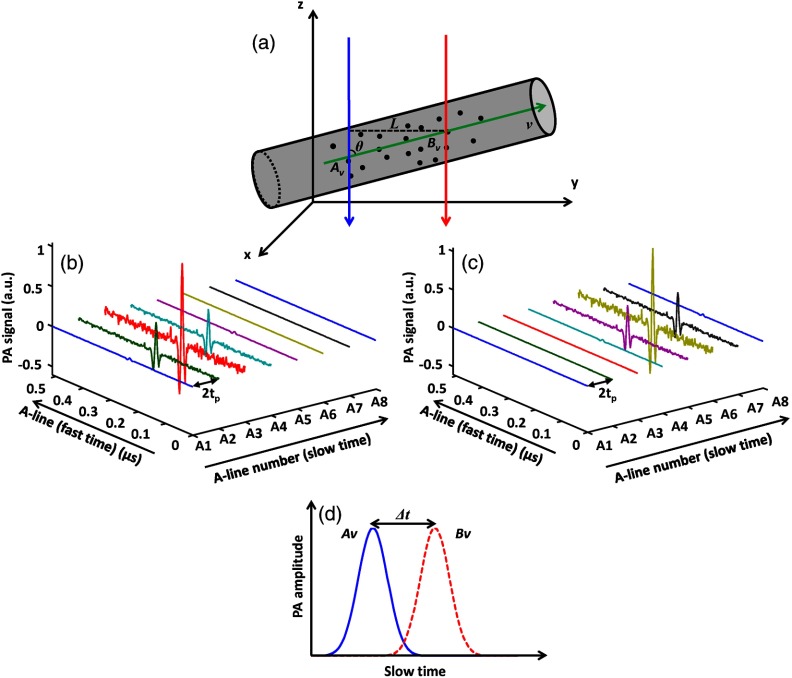
The principle of cross-correlation-based flow velocity measurement is depicted in Fig. 1. Two parallel laser beams, separated in space by a distance , alternately illuminate the measurement region of a blood vessel. The time interval between two consecutive laser pulses is . The flow is assumed to be laminar and linear. An in-plane streamline with a velocity is drawn as a green arrow in Fig. 1(a). The points of intersection between the two beams and the streamline are denoted as and . Both points lie within the acoustic focus of the ultrasonic transducer. Radiofrequency PA A-lines, referred to as “fast-time-resolved” PA signals, are acquired from each beam alternately at half of the pulse repetition rate of the laser [Figs. 1(b) and 1(c)]. A series of fast-time-resolved signals is time gated according to the depths of and . PA amplitudes of all A-lines at these depths are extracted by taking the maximum amplitude projection (MAP) of the A-lines. Subsequently, a series of PA amplitudes from A-line sequences acquired from both points is converted to two envelopes, referred to as “slow-time” PA profiles. When the same group of particles traverses and , the slow-time PA profiles from and appear with identical shapes and with a time shift [Fig. 1(d)]. The time shift is computed with the cross-correlation of the slow-time PA profiles from and . The flow velocity is calculated by
| (1) |
where is the angle of the particle flow direction with respect to the detection () axis. In addition, the flow direction can be determined from the sign of . Therefore, both flow speed and direction are measured by the cross-correlation method. Moreover, flow velocity at any selected depth can be measured.
Fig. 1.
Principle of flow measurement by PAM based on cross correlation. (a) Two laser beams (blue and red arrows) illuminate the measurement area of a blood vessel alternately. The axes of the two beams are separated by distance . Sequential A-lines are acquired at (b) and (c) at an interval time of . (d) The slow-time photoacoustic (PA) profiles from and are shifted in time by .
2.2. Experimental Setup
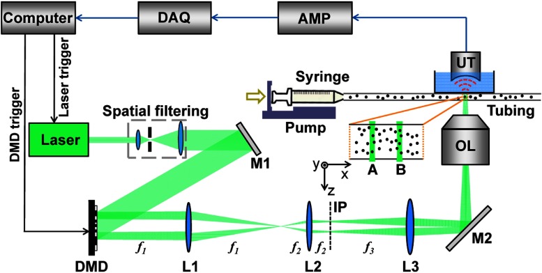
Two requirements are imposed by the proposed method. First, the voxel size should be small enough that the PA signal fluctuation induced by the variations of the particle density within the voxel is greater than the noise. Second, two spatially separated laser beams must be delivered at a high-repetition rate, in order to enable measuring a fast flow velocity. We integrated a digital micromirror device (DMD) (.7XGA DDR Discovery™ 4100, Texas Instruments, Dallas, Texas) with an optical resolution photoacoustic microscopy (OR-PAM) system to satisfy these two requirements (Fig. 2). A diode-pumped solid-state laser (INNOSLAB, Edgewave, Würselen, Germany, ) with a repetition rate of 10 kHz () was used as the illumination source. This laser had maximum output pulse energy of 300 μJ, and the pulse duration was 10 ns. After spatial filtering and collimation, the expanded laser beam was incident on the DMD. Patterns generated by micromirrors on the DMD were imaged into the target. A 50-MHz ultrasound transducer (V214-BB-RM, Olympus, Center Valley, Pennsylvania) with a 4.4-mm radius of curvature acoustic lens carved in its delay line, was used in our system. This transducer was placed confocally with the objective lens. Fast-time-resolved PA signals (A-lines) were amplified and then acquired by a 12-bit digitizer (ATS9350, AlazarTech, Pointe-Claire, Quebec, Canada). The entire system was synchronized by a multifunction data acquisition card (PCI-6251, National Instruments, Austin, Texas).
Fig. 2.
Schematic overview of the setup, not to scale. AMP, signal amplifiers and filters; DAQ, data acquisition; DMD, digital micromirror device; IP, intermediate image plane; L1–L3, lenses (focal lengths ); M1 and M2, mirrors; OL, objective lens; UT, ultrasound transducer.
The DMD consists of an array of micromirrors with a pitch distance of 13.68 μm. To realize the “ON” or “OFF” state, each micromirror can be latched in either the or position from the DMD surface normal. The entire device, therefore, functions as a binary-amplitude spatial light modulator. As the most widely adopted spatial light modulator, DMD has advantages in operation speed, stability,19 and reliability.20 Two binary patterns were encoded on the DMD in our experiments. For the first pattern, a micromirror square was turned “ON,” whereas the rest of micromirrors stayed “OFF.” The second pattern had the identical square pattern but was spatially shifted along the flow direction by a set distance. For most experiments presented in this article, this distance was chosen to be 2.63 mm. When alternately imaged into the target, these two patterns formed two laser beams. Each beam had a diameter , and the separation between these beams was . The DMD was synchronized with the laser at a rate of 10 kHz, resulting in an A-line repetition rate of 5 kHz (interval time 0.2 ms) from each beam.
We measured the flow of microspheres in a straight capillary tubing (60985-700, , VWR, Radnor, Pennsylvania). Three sizes of microspheres [17137-15 (diameter , ), 15714-5 (, ), and 24294-2 (, ), Polysciences, Warrington, Pennsylvania] were separately suspended in water. The suspensions were pumped into the tubing through a syringe, and the flow speed was controlled by a syringe pump (BSP-99M, Braintree Scientific, Braintree, Massachusetts). For each measurement, pulses were used for each laser beam to acquire a series of PA A-lines at a 5 kHz rate for a given detection time . For a selected fast-time window, we applied MAP to all measured A-lines to detect the slow-time PA profile, then correlated the two slow-time PA profiles and averaged the multiple correlation results to determine the flow velocity.
3. Experimental Results
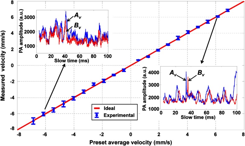
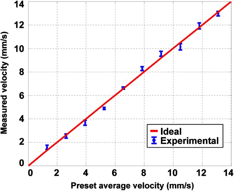
In the first experiment, we used 10-μm-diameter microspheres to measure the flow velocity (Fig. 3). The red line with the legend of “Ideal” in this figure and in the following figures represents measured flow velocities equal to the preset values. The flow velocity was varied from to , which covers the normal physiological flow velocity range in arterioles with diameters .21 The tubing was adjusted to be perpendicular to the detection axis of the ultrasound transducer () and to be in the same plane as the two laser beams. For each measurement, we observed an expected positive or negative time shift from the raw data (insets in Fig. 3). The average velocity and standard error at each data point were computed from 10 measurements. The measured velocities agreed well with the preset average flow speeds in both directions. We used the root-mean-square error of prediction (RMSEP) to describe the measurement accuracy,22
| (2) |
where systematic error and random error are defined as
| (3) |
and
| (4) |
Fig. 3.
Measured transverse flow velocities using 10-μm-diameter microspheres. Inset figures show raw slow-time PA profiles from (blue) and (red) in Fig. 1 at two selected flow velocities and . Error bars: standard errors.
Here, , , and are the preset average velocity, measured average velocity, and measured standard error of the ’th velocity out of a total of velocities, respectively. For this experiment, the RMSEP of the measured flow velocity was quantified to be , with the systematic error and random error being 0.10 and , respectively.
In addition, we investigated the flow velocity with different particle sizes (Fig. 4). Experimental results evidently illustrate that the measured flow velocity is independent of the particle size [Fig. 4(a)] within the preset range . A detailed examination of the raw data [Figs. 4(b)–4(d)] reveals that measured slow-time PA profiles were modulated with different intensities and time durations, which resulted both from different particle sizes and from the relative positions between the particles and the laser beams. For the autocorrelation method, since the flow velocity is calculated based on the time-domain narrowing effect (or on bandwidth broadening in the frequency domain) of individual profiles, it is necessary to calibrate for the particle size. On the contrary, we circumvented this calibration process by analyzing the time delay between two sequential slow-time PA profiles. Consequently, all three sets of raw data produced a consistent result, and the flow velocity was not subjected to experimental changes in particle sizes.
Fig. 4.
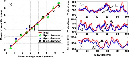
(a) Flow velocities measured using three sizes of microspheres. (b)–(d) The slow-time PA profiles from (blue solid line) and (red dashed line) in Fig. 1 with the same flow speed [dashed box in (a)] for (b) 3 μm, (c) 6 μm, and (d) 10-μm-diameter microspheres. The calculated average time shift between the blue and red slow-time PA profiles is the same regardless of individual profile shapes.
The size-independent flow measurement makes the proposed method attractive for measuring blood flow. The nonspherical shape of RBCs or RBC clusters would alter the shape of the slow-time PA profiles. Using previous methods, this change would increase the measurement errors. On the other hand, using the proposed method, flow velocity information is extracted from the time delay between the two slow-time PA profiles. Because the two laser beams are only 5 to 15 μm away from each other, RBCs or RBC clusters are likely to maintain their orientation when they traverse these two laser beams. Thus, the two slow-time PA profiles will still have identical shapes, and the flow speed can be accurately calculated.
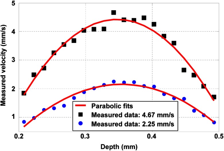
With the assumption of laminar flow, the transverse flow velocity should follow a parabolic curve in the depth direction. In our experiment, each PA A-line was time gated with a 10-ns window, which divided the entire tubing diameter uniformly into 20 streamlines of 15-μm thick each. Then the flow velocity was analyzed for each layer. Two measured depth profiles for different preset average transverse flow velocities are shown with parabolic fits in Fig. 5. Measured peak velocities of these two profiles are 2.25 and . As expected, the flow velocity peaks at the center of the tubing and falls approximately parabolically to the wall.
Fig. 5.
Measured flow velocities with parabolic fits in the depth direction, using 10-μm-diameter microspheres. The peak flow velocities are (blue dot) and (dark square).
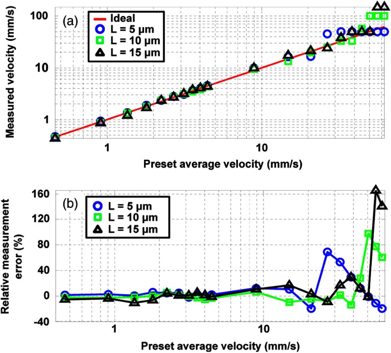
Using the proposed method, we further investigated the maximum and minimum measurable flow velocities of 10-μm-diameter microspheres. For the measurement of maximum flow velocity, the experimental results illustrated that the measured values were linear with the preset flow velocities until plateaus develop appreciably [Fig. 6(a)]. In theory, the maximum measurable velocity was reached when a flowing particle was detected only once by each laser beam. Thus, the maximum measurable velocity in our experimental setup at can be computed by Eq. (1) as
| (5) |
Fig. 6.
Quantification of the maximum measurable velocities for 10-μm-diameter microspheres. (a) Log-log plot of the measured flow velocities for three different distances. (b) Semi-log plot of the relative errors of the measured velocities.
Equation (5) shows that at a constant laser repetition rate, solely depends on the distance . For , 10, and 15 μm, the theoretical values are 50.00, 100.00, and , respectively. In comparison, the maximum relative errors of the measurements occurred at preset velocities of 26.73, 50.47, and in the range of [Fig. 6(b)]. This discrepancy comes from the discrete nature of the time shift measurement, which produces the plateaus before the theoretical values. Based on Eq. (1) ( in our experimental setup), we could not accurately measure velocities between and . The velocity difference is expressed as
| (6) |
The mean velocity within this velocity range is
| (7) |
Thus, the maximum relative error is given by
| (8) |
Equation (8) shows that when had small discrete values, the cross-correlation process had low accuracy, resulting in the plateaus in Fig. 6(a). In order to maintain acceptable velocity accuracy, we chose a two-point shift between the two slow-time PA profiles to calculate , which has a relative error . The resulting values were for , for , and for .
It is noted that a short distance between the two beams () and a long detection time () are conducive to slow flow measurement. Fundamentally, the minimum measurable velocity is limited by particle diffusion caused by Brownian motion. Particles could move out of the laser illumination area in a laminar flow during the traveling time, which would decorrelate the slow-time PA profiles from and . Based on the Brownian motion theory,23 the average displacement of particles with diameter can be calculated by
| (9) |
where , is Boltzmann’s constant, is the viscosity of the liquid, and is the absolute temperature. Given a Gaussian beam with 5-μm diameter, a 1-μm shift in space introduces only a small change of PA signals, and the two slow-time PA profiles are still correlated. Correspondingly, we can detect flow with a velocity as low as for 10-μm-diameter particles for a distance .
In addition, particles can drift in the depth direction due to gravity, drag, or convective motion due to laser-induced temperature distribution. Such depth drift could lead to de-correlation between slow-time PA profiles for a chosen fast-time gate. The following example is given to estimate the minimum measurable flow velocity. Particles with 10-μm diameter are suspended in water. Let us assume a 5% mismatch between the mass densities of the particle and the surrounding liquid due to either the material or thermal expansion of the particle. Such a level of mismatch is typical for RBCs in phosphate-buffered saline especially in the presence of a substantial temperature fluctuation. The particles mainly experience the Stokes force, buoyance, and the gravity force. In equilibrium, these particles carry a flow speed of in the depth direction. Assuming the particle starts drifting from a depth in the center of a 10-ns window, it would take 2.76 s for the particle to drift out of the time window. Correspondingly, would be for a distance .
Before this limit would be reached, however, other experimental factors might intervene in the measurement. Flow velocity, especially in biological systems, changes over time. Hence, there is a good reason to keep the detection time as short as possible. In our experiments, at a slow velocity, it was possible that the particle had not traversed the laser beam during the entire measurement; as a result, only a fraction of the slow-time PA profile of the particle was captured. Consequently, the cross-correlation result was exacerbated due to reduced correlation between the two measured slow-time PA profiles. Thus, we required that the full profile of the particle be captured by both laser beams to maintain an accurate cross-correlation result, which defined . Correspondingly, was determined by the distance , beam diameter , particle size , total time for one measurement (), and the noise-induced correlation peak shift , using
| (10) |
The typical SNR in our experiments ranged from 15 to 20, and our results showed that this produced only a negligible in the measurement; therefore, was primarily determined by the distance parameter and .
We first set the distance to three different numbers (, 10, and 15 μm) to examine [Fig. 7(a)]. We measured flows in the range of at these distances. The calculated for these distances were 0.20, 0.25, and , respectively, for a fixed time . Above the calculated , the measured results were in close agreement with the preset values. However, when the preset flow velocities were smaller than the calculated , the measured velocities stayed roughly equal to the calculated .
Fig. 7.
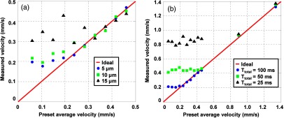
Quantification of the minimum measurable flow velocity for 10-μm-diameter microspheres. (a) Measured flow velocities for three different distances at slow preset flow velocity range for a fixed time . (b) Measured flow velocities using three different at a fixed distance .
We also studied the relation between and at a fixed distance [Fig. 7(b)]. Measurements in the range of were made using , 50, and 100 ms. The calculated for these times were 0.80, 0.40, and , respectively. Similar to Fig. 7(a), the measured flow velocity reached a constant value approximately equal to the calculated , showing good agreement with the theoretical values.
Finally, we demonstrated the feasibility of our proposed method in a biological environment. A piece of chicken tissue 250- to 300-μm thick was placed underneath the tubing as a scattering and absorbing medium. We set the distance for the experiment and used 10-μm-diameter microspheres as the target. As shown in Fig. 8, the measured flow velocities were in conformity with preset values in the entire range. From Eqs. (2)–(4), the measurement accuracy was calculated to be , with a systematic error of and a random error of .
Fig. 8.
Measured average flow velocities with underlaid chicken tissue. Error bars: standard errors.
4. Conclusion
In summary, we presented a cross-correlation-based method for transverse flow velocity measurement using DMD-based OR-PAM. The DMD was implemented to deliver two spatially separated laser beams to the target. The time shift between the two measured slow-time PA profiles was computed using cross-correlation. Both the flow speed and the direction can be determined simultaneously from the magnitude and the sign of the time shift, respectively. The proposed method was experimentally verified using microspheres of different sizes. Using a flowing aqueous suspension of 10-μm-diameter microspheres, we demonstrated that the proposed method was able to measure flow velocities in the range for microvasculature. In addition, the measured flow speed was independent of the particle size in the flow velocity range of , and it followed an expected parabolic curve in the radial direction of the tubing.
Moreover, we investigated the maximum and minimum measurable velocities in detail. At a constant laser repetition rate, the theoretical maximum measurable velocity depended only on the distance between the two beams, although the measurement accuracy degraded with increasing flow velocity. The minimum measurable velocity was theoretically limited by Brownian motion. Above the Brownian motion velocity, if a full particle profile was captured by both laser beams, the measurement accuracy was determined by two parameters: the distance between the two beams and the total detection time. A short distance and long total detection time were preferred to minimize the slowest measurable velocity. Finally, we demonstrated the feasibility of the proposed method in a phantom flow experiment using chicken tissue.
Acknowledgments
The authors thank Junjie Yao, Amy M. Winkler, Lidai Wang, Chi Zhang, Zhiyuan Shen, and Yonghong He for experimental assistance and helpful discussion, and Professor James Ballard for his close reading of the manuscript. This work was sponsored in part by National Institutes of Health grants DP1 EB016986 (NIH Director’s Pioneer Award), R01 EB008085, R01 CA134539, U54 CA136398, R01 EB010049, R01 CA157277, and R01 CA159959. L. V. W. has a financial interest in Microphotoacoustics, Inc. and Endra, Inc., which, however, did not support this work. K. I.M. has a financial interest in Microphotoacoustics, Inc., which, however, did not support this work.
References
- 1.Al-Khaldi A., et al. , “Therapeutic angiogenesis using autologous bone marrow stromal cells: improved blood flow in a chronic limb ischemia model,” Ann. Thorac. Surg. 75(1), 204–209 (2003). 10.1016/S0003-4975(02)04291-1 [DOI] [PubMed] [Google Scholar]
- 2.Fagrell B., Intaglietta M., “Microcirculation: its significance in clinical and molecular medicine,” J. Intern. Med. 241(5), 349–362 (1997). 10.1046/j.1365-2796.1997.125148000.x [DOI] [PubMed] [Google Scholar]
- 3.Peter Vaupel F. K., Okunieff Paul, “Blood flow, oxygen and nutrient supply, and metabolic microenvironment of human tumors: a review,” Cancer Res. 49(23), 6449–6465 (1989). [PubMed] [Google Scholar]
- 4.Shen Z. Y., et al. , “Transverse flow velocity quantification using optical coherence tomography with correlation,” Laser Phys. Lett. 8(4), 318–323 (2011). 10.1002/lapl.v8.4 [DOI] [Google Scholar]
- 5.Thompson R. B., McVeigh E. R., “Real-time volumetric flow measurements with complex-difference MRI,” Magn. Reson. Med. 50(6), 1248–1255 (2003). 10.1002/(ISSN)1522-2594 [DOI] [PMC free article] [PubMed] [Google Scholar]
- 6.Wang Y., Wang R., “Autocorrelation optical coherence tomography for mapping transverse particle-flow velocity,” Opt. Lett. 35(21), 3538–3540 (2010). 10.1364/OL.35.003538 [DOI] [PMC free article] [PubMed] [Google Scholar]
- 7.Shih A. Y., et al. , “Two-photon microscopy as a tool to study blood flow and neurovascular coupling in the rodent brain,” J. Cereb. Blood Flow Metab. 32(7), 1277–1309 (2012). 10.1038/jcbfm.2011.196 [DOI] [PMC free article] [PubMed] [Google Scholar]
- 8.Yoon M.-J., et al. , “Pulpal blood flow measurement with ultrasound doppler imaging,” J. Endod. 36(3), 419–422 (2010). 10.1016/j.joen.2009.12.031 [DOI] [PubMed] [Google Scholar]
- 9.Maslov K., Stoica G., Wang L. V., “In vivo dark-field reflection-mode photoacoustic microscopy,” Opt. Lett. 30(6), 625–627 (2005). 10.1364/OL.30.000625 [DOI] [PubMed] [Google Scholar]
- 10.Maslov K., et al. , “Optical-resolution photoacoustic microscopy for in vivo imaging of single capillaries,” Opt. Lett. 33(9), 929–931 (2008). 10.1364/OL.33.000929 [DOI] [PubMed] [Google Scholar]
- 11.Wang L. V., “Multiscale photoacoustic microscopy and computed tomography,” Nat. Photon. 3(9), 503–509 (2009). 10.1038/nphoton.2009.157 [DOI] [PMC free article] [PubMed] [Google Scholar]
- 12.Li L., et al. , “Photoacoustic imaging of lacZ gene expression in vivo,” J. Biomed. Opt. 12(2), 020504 (2007). 10.1117/1.2717531 [DOI] [PubMed] [Google Scholar]
- 13.Wang Y., et al. , “Fiber-laser-based photoacoustic microscopy and melanoma cell detection,” J. Biomed. Opt. 16(1), 011014 (2011). 10.1117/1.3525643 [DOI] [PMC free article] [PubMed] [Google Scholar]
- 14.Fang H., Maslov K., Wang L. V., “Photoacoustic Doppler effect from flowing small light-absorbing particles,” Phys. Rev. Lett. 99(18), 184501 (2007). 10.1103/PhysRevLett.99.184501 [DOI] [PubMed] [Google Scholar]
- 15.Chen S.-L., et al. , “Photoacoustic correlation spectroscopy and its application to low-speed flow measurement,” Opt. Lett. 35(8), 1200–1202 (2010). 10.1364/OL.35.001200 [DOI] [PMC free article] [PubMed] [Google Scholar]
- 16.Yao J., Wang L. V., “Transverse flow imaging based on photoacoustic Doppler bandwidth broadening,” J. Biomed. Opt. 15(2), 021304 (2010). 10.1117/1.3339953 [DOI] [PMC free article] [PubMed] [Google Scholar]
- 17.Yao J., et al. , “In vivo photoacoustic imaging of transverse blood flow by using Doppler broadening of bandwidth,” Opt. Lett. 35(9), 1419–1421 (2010). 10.1364/OL.35.001419 [DOI] [PMC free article] [PubMed] [Google Scholar]
- 18.Brunker J., Beard P., “Pulsed photoacoustic Doppler flowmetry using time-domain cross-correlation: accuracy, resolution and scalability,” J. Acoust. Soc. Am. 132(3), 1780–1791 (2012). 10.1121/1.4739458 [DOI] [PubMed] [Google Scholar]
- 19.Liang J., et al. , “Grayscale laser image formation using a programmable binary mask,” Opt. Eng. 51(10), 108201–108201 (2012). 10.1117/1.OE.51.10.108201 [DOI] [Google Scholar]
- 20.Douglass M. R., “Lifetime estimates and unique failure mechanisms of the digital micromirror device (DMD),” in Reliability Physics Symp. Proc., 36th Annual 1998 IEEE International, pp. 9–16, IEEE; (1998). [Google Scholar]
- 21.Barker J. H., et al. , “The hairless mouse ear for in vivo studies of skin microcirculation,” Plastic Reconstr. Surg. 83(6), 948–959 (1989). 10.1097/00006534-198906000-00003 [DOI] [PubMed] [Google Scholar]
- 22.Zhou Y., et al. , “Photoacoustic microscopy of bilirubin in tissue phantoms,” J. Biomed. Opt. 17(12), 126019 (2012). 10.1117/1.JBO.17.12.126019 [DOI] [PMC free article] [PubMed] [Google Scholar]
- 23.Sturge M. D., Statistical and Thermal Physics: Fundamentals and Applications, p. 480, A K Peters/CRC Press, Natick, Massachusetts: (2003). [Google Scholar]


