Abstract
The apparent handedness of an EM-tomography reconstruction depends on a number of conventions and can be confused in many ways. As the number of different hardware and software combinations being used for electron tomography continue to climb, and the reconstructions being produced reach higher and higher resolutions, the need to verify the hand of the results has increased. Here we enumerate various steps in a typical tomography experiment that affect handedness and show that DNA origami gold nanoparticle helices can be used as convenient and fail-safe handedness standards.
Keywords: Handedness, electron tomography, DNA origami
Biological macromolecules are chiral, meaning that they cannot be superimposed onto their mirror images by rotations or translations. Structural studies must therefore generate maps with the correct handedness before they can be properly interpreted (there are two possibilities, often spoken of as either “right” or “left”).
In single particle analysis and electron crystallography, averaging the images of many identical copies of a specimen resulted in reconstructions of sufficient resolution that handedness became immediately important. Methods to determine hand were therefore developed quickly (Finch and Klug, 1965; Radermacher, 1988). In single particle analysis, for instance, handedness can be determined by recording images of particles from two different angles. An initial reconstruction with arbitrary handedness can be used to estimate the orientations of all the particles. If the orientations of multiple particles in the two images are found to differ consistently by the experimentally known tilt angle between them, the hand is confirmed (Belnap et al., 1997; Rosenthal and Henderson, 2003).
In electron tomography, the specimen is typically unique, and the resolutions are therefore typically much lower. As a result, in the vast majority of electron tomography studies to date, the main findings have been about membrane morphologies and gross arrangements of materials, and the cell biological insights have not depended on correct hand (Gan and Jensen, 2012; McIntosh et al., 2005) This is changing, however, as cryo-preservation methods, better microscopes, CTF-correction, and sub-tomogram averaging are now producing structures with finer molecular details (Briegel et al., 2012), including even secondary structure (Bartesaghi et al., 2012).
Just as the importance of producing reconstructions with the correct hand is increasing, the number of different microscopes, cameras, and software packages being used has multiplied the challenge. Unfortunately handedness depends on conventions of angles and coordinate systems and can get flipped (inverted) by a number of operations during data collection and processing. Here we describe common steps in tomography where such ambiguities arise and show that commercially available DNA origami gold nanoparticle helices can be used as convenient molecular handedness standards.
Steps that influence handedness
Data collection
Using tilted images to determine handedness might seem straightforward at first, but a challenge arises in the myriad ways the relationship between the specimen orientation and the resulting images can get confused. The beam obviously hits the sample from above, and one can physically see from outside the microscope how the sample is tilted as the goniometer rotates, but as the image travels down the column it is rotated by arbitrarily large angles by the magnetic lenses, and the rotations vary with magnification. Modern microscope lens series are chosen to minimize the rotations, but they can still be large, especially between different imaging modes (SA, M, LM, EFTEM). While it is of course possible to determine which side of the image represents the part of the tilted specimen that was higher in the microscope by calculating power spectra of the two sides and comparing Thon rings, these checks take time and only solve one part of the handedness problem.
In early tomography work, images were recorded on film and then scanned (Ladinsky et al., 1999). Care had to be taken to ensure that films were loaded into cartridges consistently so the same side always faced the electron beam. Images are now collected almost exclusively on digital cameras, often mounted below energy filters. All digital images possess an inherent coordinate system and orientation conventions, however, including for instance, whether the image is stored and displayed as it would have appeared on the phosphor screen from “above” or “below” (the same ambiguity that arises in the decision of whether to insert a film into a scanner “right-side up” or “upside down”). Again the ambiguity of whether the image corresponds to a view from above or below can usually be resolved by comparing it to an image on the phosphor screen, but in some advanced electron cryomicroscopes the phosphor screen cannot be directly observed. In these instruments, the image on the phosphor screen is recorded by a separate camera, introducing the possibility of further ambiguities. Some data collection cameras also offer the option of how images are recorded. DigitalMicrograph, for instance, provides the checkbox ‘flip around Y axis,’ so the possibility always looms that the handedness could be inadvertently flipped, especially if a microscope is used by many individuals.
3-D reconstruction
Two critical parameters that are recorded for each image during data collection are the angle of the tilt axis within the coordinate system of the image (tilt axis rotation) and the tilt angle. The tilt axis rotation for a given microscope magnification, camera, and image-acquisition-software package is fixed and can be calibrated beforehand by tilting experiments, and the tilt angle is given by the rotation of the goniometer. After tilt-series are acquired, image alignment procedures refine the tilt axis rotation and tilt angle as well as translational shifts and a magnification factor for each image. Equally good alignments can be found with the tilt axis in two different orientations, 180° apart, but one of these will produce a reconstruction with inverted handedness. To avoid this ambiguity, it is necessary to direct the alignment software to find the axis rotation in the correct quadrant by giving it an approximately correct initial value.
It is of course vital that the alignment software follows, or at least takes account of, the conventions for the sign of the tilt angle and direction of the tilt axis rotation used by the image acquisition software. For some time SerialEM and BatchTomo (FEI’s image acquisition package) used an opposite convention for the sign of the tilt axis rotation angle. IMOD was therefore revised to detect image files from the FEI software and invert the angle, but this kind of fix is obviously version-specific. Etomo (the IMOD reconstruction interface) and RAPTOR both use the Imod program Tilt to produce the 3-D reconstruction, but apply different options for the orientation of the output slices (the legacy option ‘parallel’ used by RAPTOR inverts handedness, but ‘perpendicular’ does not). 3-D reconstructions are often trimmed, scaled, and re-oriented for easier viewing. Etomo, for instance, offers three options to reorient the tomogram: ‘None,’ ‘Rotate around X’ and ‘Swap Y and Z dimensions.’ The first two maintain the hand, the latter inverts it, using the older ‘-yz’ option to the underlying program Trimvol.
Visualization
Once a 3-D reconstruction is produced, it can be visualized in many ways. The most common approach is to view sequential slices on a computer screen. The perception of hand depends, however, on whether subsequent slices shown are “above” or “below” the previous. A viewer’s perception of hand from slices can also depend on whether the view is from outside or inside the object: if you look down on a right-handed helical coil from outside and follow it in the direction of its axis, you move to the right, but if you do the same on a bottom slice from within the coil, you travel to the left. A better approach is to generate a 3-D isosurface or volume rendering and then inspect it from the outside. Again care must be taken that the handedness is not inadvertently flipped. The command Edit>Image>Flip in the program 3dmod is frequently used, for instance, to reorient the volume and exchange xy for xz slices, but this inverts handedness in IMOD versions prior to 4.6.18.
DNA origami gold nanoparticle helices as molecular handedness standards
While it is of course possible to establish specific acquisition and processing protocols that will produce results with the correct hand, the handedness produced by a particular experimental set-up (hardware and software) as a complete system can also be verified experimentally. This can be done by creating a test object with known handedness and then producing a tomogram. We have done this before by stacking a finder grid whose letters define “left versus right” and “up versus down” on top of a second grid with large gold clusters attached or differently-sized holes to establish “above versus below” (data not shown). One problem with such an approach is, however, that the object (letters on the grid and distances between grids) are so large that very low magnifications are used to record the test tilt series, and the images can be rotated very differently than the images of typical specimens. Another potential problem with this kind of approach is that in some cases it is essential to know which side of the test object is higher than the other in the electron beam, so operators of microscopes with “auto-loaders” that retrieve grids from vertical slots must be sure this is clear.
A better approach is to use a test object of approximately the same size as the specimens of interest, like right-handed T4 phage tails, for instance. Even better is to embed a molecular standard of known handedness directly in the sample. If whole cells or cell lysates are investigated, for example, comparing ribosomes in the reconstruction to known structures can reveal whether the handedness of the reconstructions is correct. While this is especially useful for data that has already been recorded, it can be a time consuming process, and may not be successful if the preservation of the ribosomes or the resolution of the reconstructions is poor.
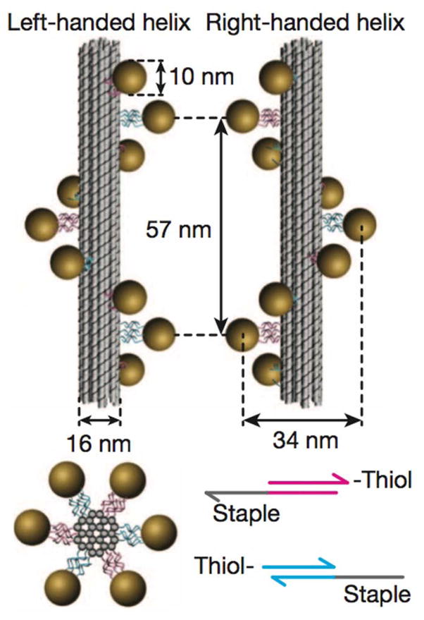
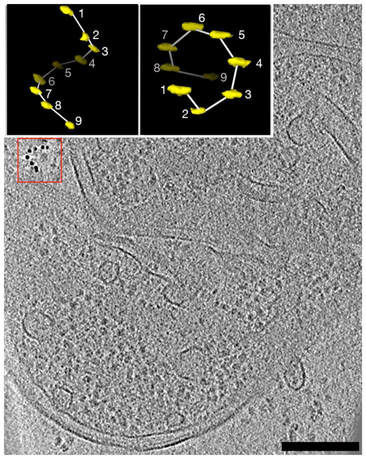
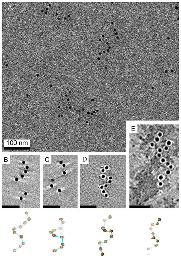
Here we show that “DNA origami gold nanoparticle helices” (Kuzyk et al., 2012) are highly useful handedness standards. These highly stable, commercially available (STS Nanotechnology; www.sts-nano.com) nanostructures are formed by a bundle of 24 DNA molecules designed to anneal into a helix with a defined hand, decorated by nine large gold clusters (Figure 1). The DNA helices of known handedness are easily visible in the reconstructed tomograms, and can even be used in place of the colloidal gold that is typically added to ET samples for image alignment (Figure 2). Simple isosurfaces of the highest-density objects in the reconstructions (the helices and other fiducials) will reveal the handedness immediately without the need for segmentation or subvolume averaging. Both right- and left-handed DNA origami gold nanoparticle helices are available. If for some reason the helices can’t be added to the sample of interest (for instance if the sample is a cryosection of a large cell that fills the entire field of view), they can be either cryo-preserved or negatively-stained on a separate grid and imaged either just before or after data-collection (Figure 3). Tilt series and reconstructions must then be produced with the exact same conditions and procedures. Such negatively-stained test samples are long lasting and can be reused many times, especially when treated with methylcellulose.
Figure 1. Schematic of DNA origami gold nanoparticle helices.

Left or right handed nanohelices (diameter 34 nm, helical pitch 57 nm) consist of nine gold nanoparticles (diameter 10 nm) that are attached to the surface of DNA origami bundles (diameter 16 nm). With permission from (Kuzyk et al., 2012).
Figure 2. DNA origami gold nanoparticle helices as molecular handedness standards.

Left-handed DNA origami gold nanoparticle helices (one example in red box) were mixed together with colloidal gold and Escherichia coli lysates, plunge-frozen, and imaged tomographically. An isosurface representation of the DNA origami gold nanoparticle helix with the attached 9 gold particles (yellow) and the modeled helix (white) is shown in the insets on the left (produced with 3dmod). Rotating the helix around the “x” (horizontal) axis reveals that the correct handedness has been maintained throughout the process (particle 1 is in the foreground and 9 is in the background). Bar: 200 nm.
Figure 3. Additional example reconstructions of DNA origami gold nanoparticle helices in vitreous ice and negative stain.

A, overview image of negatively stained, left handed helices.
B, C: Slices through cryotomograms of left handed nanohelices frozen in vitreous ice.
D, E: Slices through tomograms of left handed helices in negative stain imaged with 2 different magnifications. Scale Bars B–E: 50 nm. 3D models of the complete helices are shown below, with bright blue rods connecting particles in the foreground, dim blue rods connecting particles in the background.
Acknowledgments
We thank Tim Liedl and Robert Schreiber for the DNA origami gold nanoparticle helices, Mark S. Ladinsky for negative stain sample preparation and cryosectioning, Paul Rothemund for helpful advice and discussions, Lu Gan and Alasdair McDowall for helpful discussions and technical support. We thank Julio Ortiz, Friedrich Förster, John Heumann and Martin Beck for helpful communication. This work was supported in part by the Beckman Institute at Caltech as well as NIH grants R01 GM094800B and 2P50GM082545-06 to GJJ and P41GM103431 to A. Hoenger.
Footnotes
Publisher's Disclaimer: This is a PDF file of an unedited manuscript that has been accepted for publication. As a service to our customers we are providing this early version of the manuscript. The manuscript will undergo copyediting, typesetting, and review of the resulting proof before it is published in its final citable form. Please note that during the production process errors may be discovered which could affect the content, and all legal disclaimers that apply to the journal pertain.
References
- Bartesaghi A, Lecumberry F, Sapiro G, Subramaniam S. Protein secondary structure determination by constrained single particle cryo-electron tomography. Structure. 2012;20:2003–2013. doi: 10.1016/j.str.2012.10.016. [DOI] [PMC free article] [PubMed] [Google Scholar]
- Belnap DM, Olson NH, Baker TS. A method for establishing the handedness of biological macromolecules. J Struct Biol. 1997;120:44–51. doi: 10.1006/jsbi.1997.3896. [DOI] [PubMed] [Google Scholar]
- Briegel A, Li X, Bilwes AM, Hughes KT, Jensen GJ, Crane BR. Bacterial chemoreceptor arrays are hexagonally packed trimers of receptor dimers networked by rings of kinase and coupling proteins. Proc Natl Acad Sci USA. 2012;109:3766–771. doi: 10.1073/pnas.1115719109. [DOI] [PMC free article] [PubMed] [Google Scholar]
- Finch JT, Klug A. Structure of viruses of the papilloma-polyoma type III. Structure of rabbit papilloma virus with an appendix on the topography of contrast in negative-staining for electron microscopy. J Mol Biol. 1965;13:1–12. doi: 10.1016/s0022-2836(65)80075-4. [DOI] [PubMed] [Google Scholar]
- Gan L, Jensen GJ. Electron tomography of cells. Quart Rev Biophys. 2012;45:27–56. doi: 10.1017/S0033583511000102. [DOI] [PMC free article] [PubMed] [Google Scholar]
- Kuzyk A, Schreiber R, Fan Z, Pardatscher G, PRoller EM, Högele A, Simmel FC, Govorov AO, Liedl T. DNA-based self-assembly of chiral plasmonic nanostructures with tailored optical response. Nature. 2012;483:3110314. doi: 10.1038/nature10889. [DOI] [PubMed] [Google Scholar]
- Ladinsky MS, Mastronarde DN, McIntosh JR, Howell KE, Staehlin LA. Golgi structure in three dimensions: Functional insights from the normal rat kidney cell. J Cell Biol. 1999;144:1135–1149. doi: 10.1083/jcb.144.6.1135. [DOI] [PMC free article] [PubMed] [Google Scholar]
- McIntosh R, Nicastro D, Mastronarde D. New views of cells in 3D: an introduction to electron tomography. Trends Cell Biol. 2005;15:43–51. doi: 10.1016/j.tcb.2004.11.009. [DOI] [PubMed] [Google Scholar]
- Radermacher M. Three-dimensional reconstruction of single particles from random and nonrandom tilt series. J Electron Microsc. 1988;9:359–394. doi: 10.1002/jemt.1060090405. [DOI] [PubMed] [Google Scholar]
- Rosenthal PB, Henderson R. Optimal determination of particle orientation, absolute hand, and contrast loss in single-particle electron cryomicroscopy. J Mol Biol. 2003;333:721–745. doi: 10.1016/j.jmb.2003.07.013. [DOI] [PubMed] [Google Scholar]


