Abstract
Differential phase-contrast (DPC) technique is promising as the next breakthrough in the field of X-ray CT imaging. Utilizing the long ignored X-ray phase information, Differential phase-contrast (DPC) technique has the potential of providing us with projection images with higher contrast in a CT scan without increasing the X-ray dose. While traditional absorption-based X-ray imaging is not very efficient at differentiating soft tissues, differential phase-contrast (DPC) is promising as a new method to boast the quality of the CT reconstruction images in term of contrast noise ratio (CNR) in soft tissue imaging. In order to validate and investigate the use of DPC technique in cone-beam CT imaging scheme, a new bench-top micro-focus DPC-based cone-beam computed tomography DPC-CBCT system has been designed and constructed in our lab for soft tissue imaging. The DPC-CBCT system consists of a micro-focus X-ray tube (focal spot 8 μm), a high-resolution detector, a rotating phantom holder and two gratings, i.e. a phase grating and an analysis. The detector system has a phosphor screen, an optical fiber coupling unit and a CMOS chip with an effective pixel pitch of 22.5 microns. The optical elements are aligned to minimize unexpected moiré patterns, and system parameters, including tube voltage (or equivalently X-ray spectrum), distances between gratings, source-to-object distance and object-to-detector distance are chosen as practicable to be applied in a rotating system. The system is tested with two simple phantoms for performance evaluation. 3-D volumetric phase-coefficients are reconstructed. The performance of the system is compared with conventional absorption-based CT in term of contrast noise ratio (CNR) under the condition of equal X-ray dose level.
Keywords: Phase Contrast, Differential phase-contrast, cone beam CT
1. INTRODUCTION
Phase-contrast technique is promising as the next breakthrough in X-ray imaging and CT field. Utilizing the long ignored X-ray phase information, phase contrast technique has the potential of providing higher contrast projection images in a CT scan thus leading to a more realistic reconstruction of the scanned object. In the past decades, various phase-contrast techniques have been developed for X-ray imaging, including X-ray interferometry which measures the phase shift itself [1–3], diffraction enhanced imaging which measures the first derivative of phase shift [4–6] and in-line propagation method which measures the Laplacian of phase shift [7–9]. However, due to the requirement of high spatial coherence, most of the methods above are limited to the use of synchrotron sources or micro-focus X-ray tubes that are unpractical for clinical applications. Synchrotron sources are typical huge in size, highly costly, and with limited availability while current micro-focus X-ray tube generally suffers from low output power, rendering it inappropriate for most clinical or research imaging tasks.
Differential phase-contrast (DPC) technique is a newly developed method that greatly looses the coherence requirement for phase-contrast X-ray imaging. Based on a set of gratings, i.e. one phase grating and one analysis grating, the method extracts the phase information from a set of acquired images via the approach of phase stepping. It also has the potential to use a hospital-grade X-ray tube by adding into the DPC imaging system a source grating which divides the incident beam from a big focal spot into several narrow line sources. Detailed principles of the grating-based DPC system have been well documented [10–12]. As DPC method measures the first derivative of phase projection, it falls into the second category as listed above.
As absorption-based X-ray CT is not very efficient in differentiate soft tissues, it is natural to extend the DPC technique to tomography imaging [12] especially for soft tissue imaging. In our lab, we are working on implementing the differential phase contrast (DPC) technique in a cone beam CT (CBCT) bench top imaging system[13][14]. The resulting system enables us to differential-phase-contrast-based cone-beam CT (DPC-CBCT) scans which are expected to yield reconstruction images of better quality compared with absorption-based CT scans for the same X-ray dose level. The conventional CBCT reconstruction algorithm a has been modified into a DPC-CBCT reconstruction algorithm.
In this work, we report detailed information of design and construction of a table-top DPC-CBCT system. As an initial test of the diffraction grating system, a micro-focus tube is used in order to satisfy the spatial coherence requirement.
2. METHODS AND MATERIALS
2.1 System components
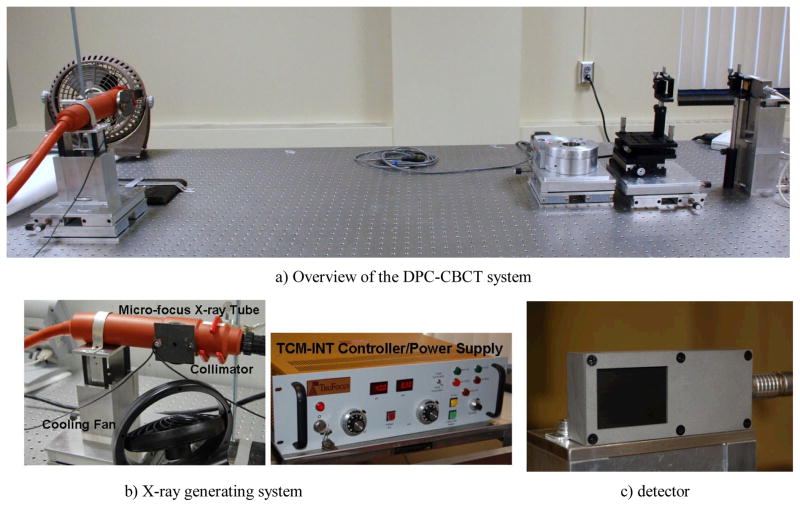
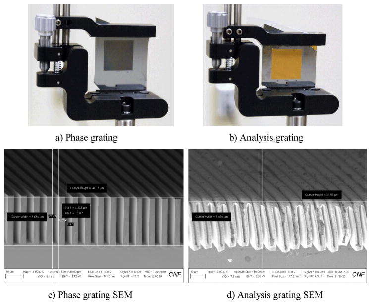
A bench-top differential phase-contrast cone beam CT system was designed and built on top of an optical table to validate the principle of proposed DPC-CBCT imaging scheme. The picture of the bench-top DPC-CBCT system is shown in Fig. 1a). The major components include an X-ray generating system Fig. 1b), an ultra high resolution detector system Fig. 1c), a set of gratings, including one phase grating and one analysis grating Fig. 2, a tomography sample stage, an optical table and controlling software.
Figure 1.
Picture of the bench-top DPC-CBCT system: a) overview of the DPC-CBCT system, b) X-ray generating system, and c) detector
Figure 2.
Picture of the set of gratings a) phase and b) analysis grating, c) and d) are images of the phase and analysis gratings examined using SEM respectively.
The X-ray generating system is a TFX-8100SW (Trufocus, Watsonville, CA) micro-focus X-ray tube. It has a stationary tungsten target, a nominal focal size of 8 μm, a maximum anode power of 12 watts and a kVp range of 10 to 90 kVp. A RadEye HR high resolution detector system (Rad-icon Imaging Corp, Santa Clara, CA), CMOS-based with a scintillator screen, is used to capture the X-ray images. The scintillator (made of Gd2O2S) of the chosen detector system is able to convert the X-ray photons to visible photons with a good spectrum response from 10keV to 90keV. It has a detector pitch of 22.5 μm, an active area of 36 mm × 27 mm, an image matrix of 1600 × 1200 and a dynamic range of 14 bits (~1:16000). A PXD 1000 frame grabber (Imagenation, Beaverton, OR) is installed and connected via a PCI slot to a computer in order to control the exposure time and image acquisition of the detector.
The major challenge in design and construction of the DPC-CBCT system is the fabrication and alignment of the gratings. In design, the phase grating is 2cm width by 2cm height and has a designed period of 8 micron. It has a duty circle of 50% and a grove height of 30 micron. The analysis grating is also 2cm by 2cm and has a designed period of 4.14 micron. It has a duty circle of 50%, and a grove height of 20 micron. The gratings are self-manufactured in the Cornell Nanofabrication facility via KOH chemical etching to achieve the desired grating structure, electroplating for the gold layer on the analysis grating, and etc.[15]. The images of both grating, including images examined using SEM, are shown in Fig. 2.
Both gratings are fixed on customized grating mounts (CYM-2R cylindrical lens positioner, SP posts and VPH post holders, Newport, Irvine, CA) that have tilt adjustment with an angular sensitivity of 30 arc sec (0.145 arc milliradians). The analyzer grating is placed close to the detector surface, and at the first fractional Talbot distance, the phase grating is mounted on a linear stage (VP-25XA, Newport, Irvine, CA) with a step accuracy of 0.1 μm.
2.2 System construction and configuration
The major system parameters of the bench-top differential phase-contrast cone beam CT system as shown in Fig. 1. are listed in Table 1.
Table 1.
Bench-top DPC-CBCT system parameters
| Focal spot size | 8 μm |
| Detector pixel size | 22.5 μm |
| Source-to-phase-grating distance | 1200 mm |
| Phase-to-analysis-grating distance | 159.6 mm |
| Object-to-detector distance | 456 mm |
| Magnification factor | 1.425 |
| Field of view | 32 mm × 24 mm |
| Cone angle | < 2° |
| Tube peak voltage | 40 kVp |
| Tube current | 0.3 mA |
| Exposure time per projection | 6.7 seconds |
| Projection number | 60 |
| Recon voxel size | (15.8 μm)3 |
| Phase grating period | 8.0 micron (duty circle 53%) |
| Phase grating groove height | 28 micron |
| Analysis grating period | 4.1 micron (duty circle 44%) |
| Analysis grating groove height | 31 micron |
| DPC steps | 8 |
8 steps shift scheme is chosen as to limit the impact of phase wrapping which become more serious with fewer steps. For comparison, the absorption-based CBCT system is implemented by removing the phase and analysis gratings, Fig. 3.
With the distance between X-ray source set as 1.36m, the refraction of the X-ray is limited, yet inline DPC might result in enhanced edges in the attenuation images. In principle, though a micro-focus tube is used, this is still an attenuation-based CBCT imaging scheme.
2.3 Reconstruction algorithm
Intuitively, the phase shift (phase projection) at each view angle can be obtained simply through a one dimensional integral along the direction of derivative since the DPC image is the first derivative of phase shift, and the reconstruction algorithms can be readily applied to reconstruct the linear phase coefficient (LPC) φ. This approach may work in some circumstances, but it fails for VOI imaging when truncation occurs because in this case the integration is not accurate up to an undetermined integration constant. It also cripples when there are singularities or the noise is not uniform in the DPC image, because the errors of singularities or non-uniform noises will be accumulated in the 1D integral operations and cause severe artifacts. When the beam angle of the DPC scheme is small, which is exactly the case of our system, the parallel beam assumption is valid and a filtered backprojection (FBP) algorithm[16] can be used for approximate reconstruction using the DPC images. This reconstruction algorithm uses a Hilbert filter and it can be simply formulated as:
| (1) |
where
| (2) |
3. RESULTS
The constructed DPC-CBCT system is evaluated using two self-made phantoms. The contrast evaluation phantom. mainly consisting of a small plastic tube inside a larger cylinder is shown in Figure. 4
Figure 4.
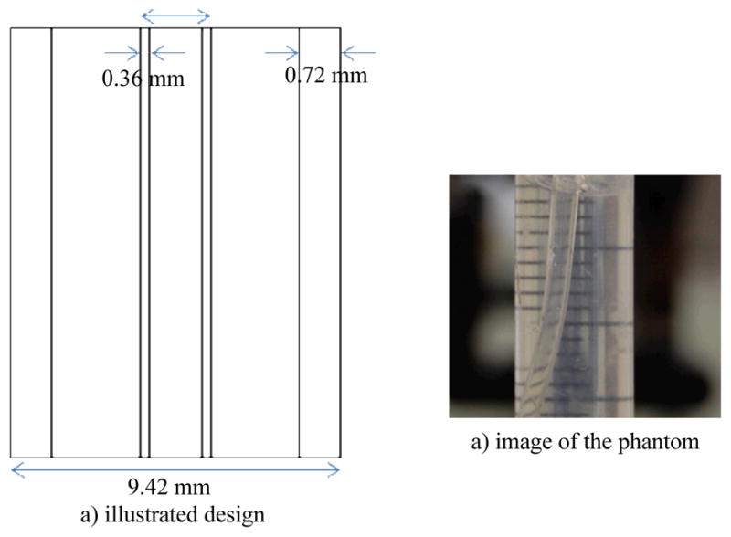
Images of the self-made contrast evaluation phantom, a) illustrated design, b) image of the phantom
Both the small tube and the cylinder are filled with water in order to simulate the soft tissue scenario in which low contrast between the object and the environment is typically observed. For noise and uniformity assessment, the small tube is removed from the phantom above.
The phase grating and the analyzer grating have to be aligned to manifest the best phase-contrast effect. In the bench-top system, the analyzer grating is fixed while the phase grating is adjusted with three-way rotation and one-way translation. The DPC images are acquired using a 8 steps 8 average scheme, that is to take the temporal average of 8 sequential images acquired at a given grating position for 8 DPC steps. For comparison, absorption-based images are acquired. The X-ray dose levels for both the absorption-based and DPC based CBCT scans are strictly controlled to be the same. That is to say with 8 steps DPC scheme, 8 times more average time will be applied for the absorption-based scans. As shown in Fig. 3, gratings are removed for the absorption-based CBCT scans.
Figure 3.
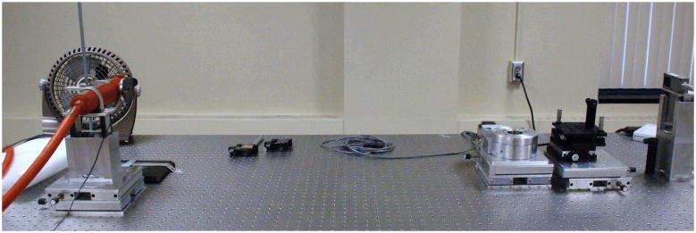
Experimental setups for attenuation-based cone-beam CT
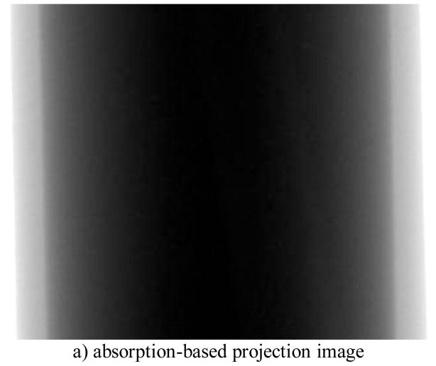
The acquired DPC and absorption based images are shown in Fig. 5a) and b) respectively.
Figure 5.
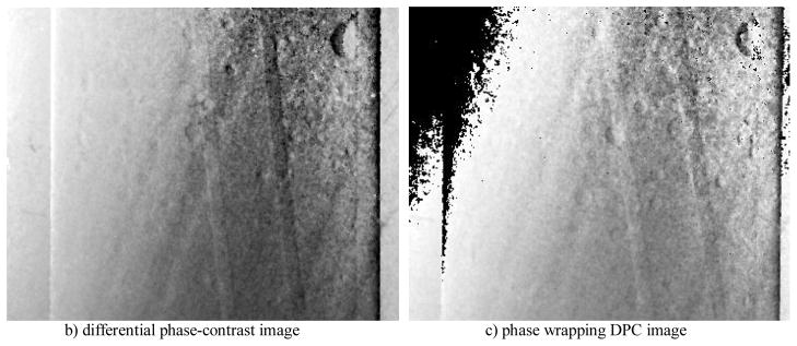
Comparison of absorption-based projection image and differential phase-contrast image of the contrast phantom, a) absorption-based projection image, b) differential phase-contrast image, and c) phase wrapping DPC image
We observe that the small tube become obvious in the DPC images than the absorption-based. The edges of the small tubes, both inner and outer are enhanced. However, several artifacts are also observed in the DPC images, which are due to the imperfection of the gratings.
Phase wrapping effect has been noticed in data processing Fig. 5c). This is due to the fact that two angles are essentially the same with a difference of 2π, yet may appear as different values in a DPC images. Discontinuities due to phase wrapping effect is observed in DPC images as shown in Fig. 5c). A simple unwrapping algorithm is applied for correction of phase wrapping by detecting discontinuities. It is also noticed that phase wrapping effect becomes more prominent with fewer DPC steps.
The DPC-CBCT scan reconstructions of the phantom are made using the modified FBP algorithm as narrated in section 2.3. For comparison, absorption-based CBCT scan reconstructions are made. A ramp filter is applied in the absorption-based CBCT scans reconstruction algorithm.
Contrast and noise of the reconstructions are measured at approximately the same positions in the images above chosen in the preference of fewer other artifacts. The contrast and noise are normalized by the average of “water” intensity measured near the position for fair comparison. The measurements for both DPC images and Absorption images are listed in Table 2.
Table 2.
Contrast-noise-ratio Comparison
| Contrast-noise-ratio (CNR) | Axial | Sagittal |
|---|---|---|
| DPC Images | 4.4 | 2.4 |
| Absorption-based Images | 3.34 | 1.6 |
From the table above, we show that DPC-CBCT reconstruction images have contrast noise ratio (CNR) comparable to or higher than absorption-based CBCT reconstruction images. The difference in CNR is largely due to remarkably lower noise level rather than higher contrast. It should be noticed here that inline phase contrast might result in enhanced contrast for the absorption-based images.
However. the uniformity of the DPC-CBCT reconstruction images, as shown in Fig. 6, is low. A visible non-uniform background is present, with up to 30% change in intensity average from one part of the image to another. The edge of the sagittal reconstruction images are considerably darker than the middle, and so does the outer part of the axial reconstruction image than the inner. Noise level also varies to some extent from one part of the image to another. Such uniformity might largely be caused by the failure of background subtraction as focal spot shift in the X-ray tube leads to differences in the background of images taken at two different times. We will be able to improve the uniformity profoundly with a probably more stable X-ray generation system, i.e. a hospital grade X-ray tube combined with a source grating.
Figure 7.
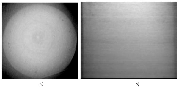
DPC-CBCT image of the water phanton, (a) axial slice and b) sagittal slices.
4. DISCUSSION AND CONCLUSION
We report here the design, construction, and performance evaluation of a bench-top differential phase-contrast cone beam CT (DPC-CBCT) system. Two sets of reconstruction images were generated and compared: the reconstruction using attenuation-based images, the reconstruction using DPC images. Two phantoms were used for the evaluation, one made up of a small plastic tube within water simulating vessel (soft tissue) for contrast assessment, the other with mere water for noise and uniformity assessment. The performance of the system is compared with conventional CT in term of CNR under the condition of equal X-ray dose level.
Comparing DPC and attenuation projection images, we find the edge of the tube become much more prominent in the DPC projection image. Several artifacts can be observed in the DPC projection image, which is due to the imperfection of the self-fabricated gratings.
Comparing the DPC recon images with the absorption-based recon images, we find that CNR of the DPC-CBCT images are comparable to or higher than images generated using the attenuation CT system. However, we notice that due to the imperfection of our gratings, the performance of the system is compromised to some extent. Several major artifacts were introduced during the phase retrieval process due to imperfection of the gratings. Examining the recon images of the noise assessment phantom, we find the uniformity of the reconstructed image is low due to the lack of background subtraction. A better pair of gratings will lead to further improvement in our DPC-CBCT system while a source grating combined with hospital grade X-ray tube will be introduced into the system.
The system will be optimized and characterized in more detail to improve the reconstruction accuracy. A larger and better patch of gratings will be made in order to fully exploit the merit of the differential phase contrast technique. Conventional CBCT image quality evaluation criteria, including background uniformity, reconstruction linearity, spatial resolution, contrast resolution and noise properties will be quantified. As the attenuation of an object influences the effect of phase-contrast, the system will be evaluated using objects with different attenuation abilities to characterize the effect of attenuation as well.
Figure 6.
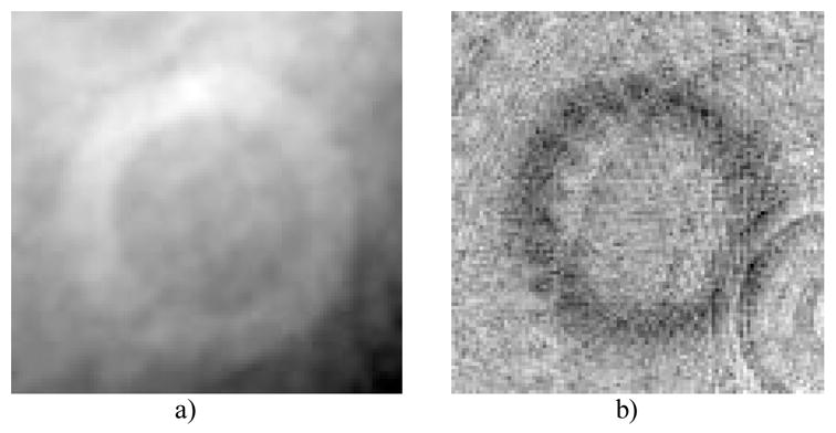
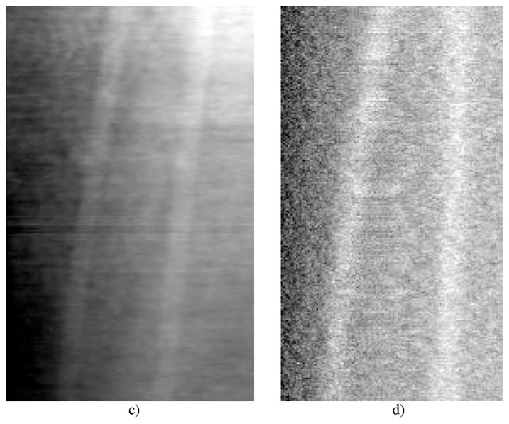
Reconstruction comparison of attenuation-base CBCT (a) and (c), in-line PC-CBCT (b) and (d), (a) through (b) are axial slices and (c) through (d) are sagittal slices.
Acknowledgments
This work was supported in part by NIH Grants R01 9 HL078181, 4 R33 CA94300 and R01 CA 143050. Part of this work was performed at the Cornell NanoScale Facility (CNF), a member of the National Nanotechnology Infrastructure Network, which is supported by the national Science Foundation (Grant ECS 0335765).
References
- 1.Momose A. Demonstration of phase-contrast X-ray computed tomography using an X-ray interferometer. Nucl Instr And Meth In Phys Res A. 1995;352:622–628. [Google Scholar]
- 2.Takeda T, Momose A, Wu J, Yu Q, Zeniya T, Lwin T, Yoneyama A, Itai Y. Vessel Imaging by interferometric phase-contrast X-ray technique. Circulation. 2002 Apr 9;:1708–1712. doi: 10.1161/01.cir.0000012752.35225.6c. [DOI] [PubMed] [Google Scholar]
- 3.Momose A, Takeda T, Itai Y. Phase-contrast X-ray computed tomography for observing biological specimens and organic materials. Rev Sci Instrum. 1995;66(2):1434–1436. [Google Scholar]
- 4.Chapman D, Thomlinson W, Johnston RE, Washburn D, Pisano E, Gmur N, Zhong Z, Menk R, Arfelli F, Sayers D. Diffraction enhanced X-ray imaging. Phys Med Biol. 1997;42:2015–2025. doi: 10.1088/0031-9155/42/11/001. [DOI] [PubMed] [Google Scholar]
- 5.Dilmanian FA, Zhong Z, Ren B, Wu XY, Chapman LD, Orion I, Thomlinson WC. Computed tomography of X-ray index of refraction using the diffraction enhanced imaging method. Phys Med Biol. 2000;45:933–946. doi: 10.1088/0031-9155/45/4/309. [DOI] [PubMed] [Google Scholar]
- 6.Chou C, Anastasio M, Brankov J, Wernick M, Brey E, Connor E, Jr, Zhong Z. An extended diffraction-enhanced imaging method for implementing multiple-image radiography. Phys Med Biol. 2007;52:1923–1945. doi: 10.1088/0031-9155/52/7/011. [DOI] [PubMed] [Google Scholar]
- 7.Snigirev A, Snigireva I, Kohn V, Kuznetsov S, Schelokov I. On the possibilities of X-ray phase contrast microimaging by coherent high-energy synchrotron radiation. Rev Sci Instrum. 1995;66(12):5486–5492. [Google Scholar]
- 8.Wilkins SW, Gureyev TE, Gao D, Pogany A, Stevenson AW. Phase-contrast imaging using polychromatic hard X-rays. Nature. 1996;384:335–338. [Google Scholar]
- 9.Wu X, Liu H, Yan A. X-ray phase-attenuation duality and phase retrieval. Optics Letters. 2005;30:379–381. doi: 10.1364/ol.30.000379. [DOI] [PubMed] [Google Scholar]
- 10.Pfeiffer F, Weitkamp T, Bunk O, David C. Phase retrieval and differential phase-contrast imaging with low-brilliance X-ray sources. Nature Physics. 2006;2:258–261. [Google Scholar]
- 11.Kottler C, Pfeiffer F, Bunk O, Grunzweig C, Bruder J, Kaufmann R, Tlustos L, Walt H, Briod I, Weitkamp T, David C. Phase contrast X-ray imaging of large samples using an incoherent laboratory source. Phys Stat Sol A. 2007;204(8):2728–2733. [Google Scholar]
- 12.Pfeiffer F, David C, Bunk O, Donath T, Bech M, Le Duc G, Bravin A, Cloetens P. Region-of-interest tomography for grating-based X-ray differential phase-contrast imaging. Phys Rev Lett. 2008;101:168101. doi: 10.1103/PhysRevLett.101.168101. [DOI] [PubMed] [Google Scholar]
- 13.Cai W, Ning R. Dose efficiency consideration for volume-of-interest breast imaging using X-ray differential phase-contrast CT. Proc SPIE. 2009;7258:72584D. [Google Scholar]
- 14.Cai W, Ning R. Design and Construction of a Micro-focus In-line Phase-contrast Cone Beam CT (PC-CBCT) System for Soft Tissue Imaging. Proc SPIE. 2010:7622–76225F. [Google Scholar]
- 15.David C, Bruder J, Rohbeck T, Grunzweig C, Kottler C, Diaz A, Bunk O, Pfeiffer F. Fabrication of diffraction gratings for hard X-ray phase contrast imaging. Microelectronic Eng. 2007;84:1172–1177. [Google Scholar]
- 16.Faris Gregory W, Byer Robert L. Three-dimensional beam-deflection optical tomographyof a supersonic jet. Applied Optics. 1988 Dec 15;27(24) doi: 10.1364/AO.27.005202. [DOI] [PubMed] [Google Scholar]


