Abstract
Vitreoretinal surgery requires delicate manipulation of retinal tissue. However, tool-to-tissue interaction forces in the order of sub-millinewton are usually below the human sensory threshold. A surgical force sensor (FS) compatible with conventional surgical tools may significantly improve the surgery outcome by preventing tissue damage. We have designed and built a miniature FS for vitreoretinal surgery using a fiber-optic common-path phase-sensitive optical coherence tomography (OCT) system where the distal end of the fiber probe forms a low-finesse Fabry–Pérot (FP) cavity between the cleaved tip of the lead-in single mode fiber and the polished back surface of a stainless steel surgical tool tip. To accurately measure the change of the FP cavity length, the cavity is interrogated by the fiber-optic common-path phase-sensitive OCT. The FP cavity was illuminated with a broadband light source, and the interferometric signal was detected using a broadband spectrometer. The phase of the interferometric signal, which is proportional to the cavity length change as well as the exerted force, was extracted. We have conducted calibration experiments to characterize our one dimensional FS. Our result shows that the FS responses linearly to force in axial direction with force sensitivity better than 0.25 millinewton.
Keywords: Fiber-optics, Fabry-Pérot interferometer, force sensor, phase sensitive
1. INTRODUCTION
Surgeon’s maneuver during microsurgery predominantly depends on visual feedback through the surgery microscope. In addition to visual feedback, tactile feedback can also help the surgeon to prevent potential tissue damage in freehand or robotic assisted surgery. However, in microsurgeries such as vitreoretinal surgery, forces exerted to ocular tissue from surgical instrument are usually too small to be sensed by humans. Gupta et al [1] report that, during vitreoretinal surgery, 75% of tool-to-tissue interaction forces were less than 7.5 mN in magnitude and that only 19% of force events at this magnitude could be felt by the surgeon As a result, a “sensory substitution” or, a force sensor (FS) is required to provide surgeons with tactile feedback [2, 3]. As the force of interest is small in magnitude, any force sensor used in vitreoretinal microsurgery has to have high sensitivity. Moreover, the size of the sensor has to be small enough so that it can be integrated into a conventional surgical vitreoretinal surgery instrument with sub-millimeter diameter. Finally, the force sensing element has to be located on the portion of the tool that is inside the eye in order to avoid confusion with forces exerted on the tool shaft by the sclera or trocar inserted into the sclera.
Force sensors based on fiber optics can be very small, mechanically stable, immune to electrical noise and sterilizable. Therefore they are ideal to be incorporated with conventional surgical tools and used as sensory substitution for tactile feedback in vitreoretinal microsurgery. One of such fiber optic force sensors is based on Fabry–Pérot interferometer (FPI) and has been used in bio-applications including surgical force sensing [4, 5].
In this study, we have designed and built a one dimensional (axial) fiber optic FS with Fabry–Pérot interferometer for potential applications in vitreoretinal surgery. In our FPI-FS, the length of FP cavity changes proportionally with force applied and we use a common-path Fourier domain optical coherence tomography (CP-FD-OCT) to interrogate the change of cavity length by phase sensitive detection [6, 7]. The common-path configuration of our OCT system leads to stable phase in the interference spectrum and thus allows us to achieve sub-nanometer sensitivity in displacement measurement [8].
2. METHOD
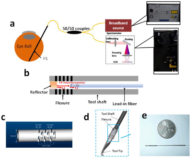
The system schematic of our FPI-FS is shown in Figure 1(a). The FP cavity that senses the force is located at the tip of a conventional surgical tool (a surgical pick in our case), which is inserted into the eye to perform surgical tasks during vitreoretinal surgery.
Figure 1.
(a) System schematic of FPI-FS; (b) details of the FS probe; (c) flexure used to bond the lead-in fiber and the metal mirror; (d)schematic of the assembled FPI-FS; (e)photo of the assembled FPI-FS pictured below a US quarter.
To interrogate the length of the cavity, we used a phase-sensitive CP-FD-OCT system which has been described in detail in our previous publication [9]. In brief, it is a spectral domain OCT system operating in 800nm wavelength range with a ~6μm axial resolution and a ~3mm imaging depth. The real time data acquisition and processing software implemented with C++ was running at a speed of 1kHz.
In our FPI-FS system, the FPI consists of a mirror and the tip of the lead-in single mode fiber as shown in Figure 1(b). The mirror is a polished back surface of a stainless steel tool tip with 0.5mm in diameter. The tip of the lead-in fiber was cleaved in right angle; therefore the light is reflected partially at the boundary between silica and air and serves as a reference. The partially reflected light from the fiber tip combines with light reflected by the metal reflector, routes through the coupler; and the two optical fields interfere. The interference spectra are detected by the spectrometer. Other components of our FS include a tool shaft, a flexure and a tool tip (pick). The tool shaft is a SS304 hypodermic tube with 0.5 mm outside diameter (25 gauge) and 50 mm length. The mirror and tool shaft is bounded by a Nitinol flexure. The flexure deforms proportionally to the force applied. Nitinol has super-elastic property (modulus of elasticity ranges from 41×103 MPa to 75×103 MPa); therefore the FP cavity has a measureable deformation with an extremely small force in the order of millinewton. As shown in Figure 1 (c), the flexure with 0.80 mm outer diameter (OD) and 0.60 mm inner diameter (ID) has five layers; each layer consists of three 40-micrometer struts; and between adjacent layers there is a 100 micrometer slot. We used Loctite medical instant adhesive to bond all the parts together. The force-sensing probe is attached to a custom made handle for experiments. Figure 1 (d) and Figure 1 (e) show the schematic and photo of the assembled tool.
As the reflectivity of the fiber tip and the polished metal surface are both relatively small, the round trip loss of optical power in the FP cavity is large. Therefore the FPI has low finesse and any higher order reflections are neglected in the following analysis.
The length of FP cavity, L, varies when there is force applied to the tool as shown in Eq. (1).
| (1) |
In Eq (1), L0 is the length of the FP cavity when there is no force exerted. δl is proportional to the force exerted to the tool and can be extracted from the phase of OCT signal.
Complex valued OCT signal at the coherence peak corresponding to the FP cavity length can be expressed as Mexp(jφ) and φ can be calculated using Eq (2). δl can thus be obtained with Eq (3)[5].
| (2) |
| (3) |
When a force along the tool shaft direction is applied to the FS, the flexure deforms proportionally with a coefficient A:
| (4) |
The coefficient A can be obtained from a calibration procedure and afterwards can be used to calculate the force according to a measured displacement.
3. RESULTS
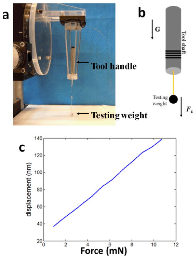
To calibrate our FS, we attached different numbers of test weights to the FS and maintained the tool shaft in the direction of gravity, as demonstrated in Figure 2(a) and (b). In our calibration experiments, each test weight was 0.897 (±0.005) mN. We searched the peak of the OCT signal; calculated the phase of the complex valued OCT signal at the peak pixel using Eq (2); and extracted the displacement from the phase using Eq (3). The obtained displacement is essentially the change of FP cavity length due to the force applied to the FS. With different numbers of testing weights, we obtained different values of displacement δl. The results are shown in Figure 2(c). Afterwards, using the known forces F and the measured displacements δl=AF+δl0, we were able to perform linear regression to extract A, which equals 10.5nm/mN.
Figure 2.
(a) Photo of calibration setup; (b) schematic of calibration setup; (c) calibration result
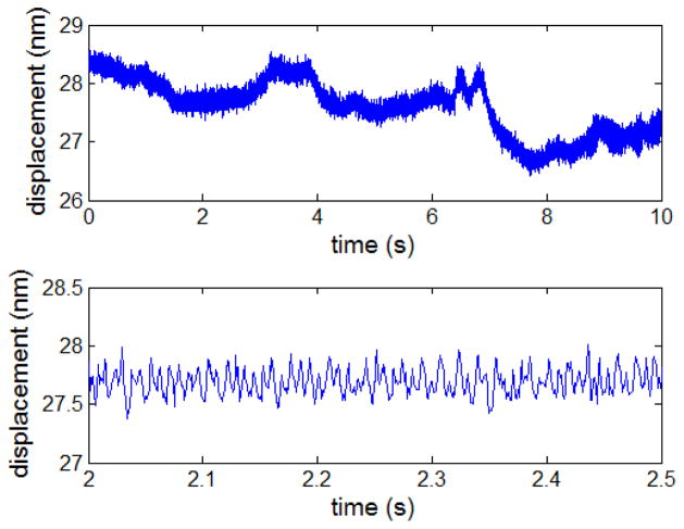
The sensitivity of our FS, or the minimum force our system can measure, is limited by our phase-sensitive OCT’s sensitivity in displacement measurement. To evaluate our system’s sensitivity, we recorded the displacement continuously for 10 seconds without any external force applied to the FS and show the results in Figure 3.
Figure 3.
Upper: displacement measured in a 10-second period of time; lower: displacement measured in a 0.5-second period of time.
As shown in the upper inset of Figure 3, the displacement signal shows slow fluctuation in a relative long period of time (10s). Such signal fluctuation is due to the environmental disturbance, such as temperature variation, mechanical vibration or change in air flow. In addition to the slow drift, the measured displacement also contains high frequency noise components, as shown in the lower inset of Figure 3. The lower inset of Figure 3 shows a rapidly varying noise with a smaller magnitude during 0.5s period. Such noise is believed to come from the laser RIN and quantum noise.
We calculated the standard deviation of displacements shown in the upper and lower insets of Figure 3. The results are 0.5nm and 0.1 nm, respectively. The environmental induced displacement fluctuation is larger. The effective force measurement sensitivity for our system was found to be is 0.05mN and no worse than 0.25mN.
4. CONCLUSION
In this study, we built and demonstrated a micro force sensing tool for vitreoretinal surgery with sub-millimeter diameter and sub millinewton sensitivity in axial direction with active sensing element at the tip of a surgical instrument which can be inserted into the eye. Our FS achieved a sensitivity better than 0.1mN and this has not been reported before to the best of our knowledge.
The use of the FPI for measuring forces in one direction could be extended to measuring forces in two or three directions (3D). Currently we are developing a 3D micro force sensing tool based on FPI technology. A different approach will be to combine in a 3D tool FPI for axial forces with fibber Bragg gratings for transversal ones.
For the intraoperative application of our FPI-FS, the accuracy of force measurement can be affected by temperature variation or air/fluids flow. During our calibration procedure, we minimized the environmental perturbation by covering the calibration setup with an encloser and performing the calibration procedure in a relatively short period of time. To reduce errors in calibration and further shorten the time required for calibration, we are currently developing a robotic calibration procedure. During surgery, such environmental perturbation might be eliminated by biasing the tool before tip-to-tissue interaction. Another difficulty involved is the proper sealing of the tool to use the FS inside of the eye (filled with liquid). This issue will be address in our future studies.
Acknowledgments
The research reported in this paper was supported in part by NIH BRP grant 1 R01 EB 007969, NSF CISST ERC EC9731748 and Johns Hopkins University internal funds.
References
- 1.Gupta PK, Jensen PS, de Juan E., Jr . MICCAI’99. Vol. 1679. LNCS; 1999. Surgical forces and tactile perception during retinal microsurgery; pp. 1218–1225. [Google Scholar]
- 2.Iordachita I, Sun Z, Balicki M, Kang JU, Phee SJ, Handa J, Gehlbach P, Taylor RH. A sub-millimetric, 0.25 mN resolution fully integrated fiber-optic force-sensing tool for retinal microsurgery. International Journal of Computer Assisted Radiology and Surgery. 2009;4:383–390. doi: 10.1007/s11548-009-0301-6. [DOI] [PMC free article] [PubMed] [Google Scholar]
- 3.Sun Z, Balicki M, Kang J, Handa J, Taylor R, Iordachita I. Development and preliminary data of novel integrated optical microforce sensing tools for retinal microsurgery. IEEE ICRA. 2009:1897–1902. [Google Scholar]
- 4.Su H, Zervas M, Furlong C, Fischer GS. A miniature MRI-compatible fiber-optic force sensor utilizing Fabry-Perot interferometer. MEMS and Nanotechnology, Conference Proceedings of the Society for Experimental Mechanics Series; 2011. pp. 131–136. [Google Scholar]
- 5.Zhang Y, Shibru H, Cooper KL, Wang A. Miniature fiber-optic multicavity Fabry-Perot interferometric biosensor. Opt Lett. 2005;30:1021–1023. doi: 10.1364/ol.30.001021. [DOI] [PubMed] [Google Scholar]
- 6.Kang JU, Han J, Liu X, Zhang K, Song CG, Gehlbach P. Endoscopic Functional Fourier Domain Common Path Optical Coherence Tomography for Microsurgery. IEEE J of Select Topic in Quantum Electron. 2010;16:781–792. doi: 10.1109/jstqe.2009.2031597. [DOI] [PMC free article] [PubMed] [Google Scholar]
- 7.Zhao Y, Chen Z, Ding Z, Ren H, Nelson JS. Real-time phase-resolved functional optical coherence tomography by use of optical Hilbert transformation. Opt Lett. 2002;27:98–100. doi: 10.1364/ol.27.000098. [DOI] [PubMed] [Google Scholar]
- 8.Zhang J, Rao B, Yu L, Chen Z. High-dynamic-range quantitative phase imaging with spectral domain phase microscopy. Opt Lett. 2009;34:3442–3444. doi: 10.1364/OL.34.003442. [DOI] [PMC free article] [PubMed] [Google Scholar]
- 9.Liu X, Balicki M, Taylor RH, Kang JU. Towards automatic calibration of Fourier-Domain OCT for robot-assisted vitreoretinal surgery. Opt Express. 2010;18:24331–24343. doi: 10.1364/OE.18.024331. [DOI] [PMC free article] [PubMed] [Google Scholar]


