Abstract
Phantom equivalents of different human anatomical parts are routinely used for imaging system evaluation or dose calculations. The various recommendations on the generic phantom structure given by organizations such as the AAPM, are not always accurate when evaluating a very specific task. When we compared the AAPM head phantom containing 3 mm of aluminum to actual neuro-endovascular image guided interventions (neuro-EIGI) occurring in the Circle of Willis, we found that the system automatic exposure rate control (AERC) significantly underestimated the x-ray parameter selection. To build a more accurate phantom for neuro-EIGI, we reevaluated the amount of aluminum which must be included in the phantom. Human skulls were imaged at different angles, using various angiographic exposures, at kV’s relevant to neuro-angiography. An aluminum step wedge was also imaged under identical conditions, and a correlation between the gray values of the imaged skulls and those of the aluminum step thicknesses was established. The average equivalent aluminum thickness for the skull samples for frontal projections in the Circle of Willis region was found to be about 13 mm. The results showed no significant changes in the average equivalent aluminum thickness with kV or mAs variation. When a uniform phantom using 13 mm aluminum and 15 cm acrylic was compared with an anthropomorphic head phantom the x-ray parameters selected by the AERC system were practically identical. These new findings indicate that for this specific task, the amount of aluminum included in the head equivalent must be increased substantially from 3 mm to a value of 13 mm.
Keywords: Head equivalent phantom, uniform phantom, Circle of Willis, fluoroscopy, digital subtracted angiography
1. INTRODUCTION
Image performance, specific task evaluation, or dose measurements of x-ray imaging systems are done using various anthropomorphic or uniform phantoms. Both phantom types mimic the specific human anatomy, morphology, and structure for which the systems were intended, using various tissue equivalents.
There is considerable literature1–9 and recommendations for the phantom type to be used for each general x-ray procedure or imaged body part. However, when confronted with new imaging technologies and specific tasks, some of these recommendations could lead to erroneous or incomplete conclusions. It is therefore necessary to modify the design of such phantoms if accurate simulations are required for new imaging technologies in newly emerging interventional procedures.10
In particular, neuro-endovascular image guided interventions (neuro-EIGI)11 are very different from many other diagnostic procedures, due to the unique location in the cranial cavity that contains the structures of interest. Image guidance includes fluoroscopy, digital angiography and digital subtraction angiography (DSA), using single or biplane angiographic C-Arms. Figure 1 demonstrates some neuro-EIGI projection peculiarities using representative slices from a CT volume. The Circle of Willis where most neuro-EIGI’s occur is located at the skull base (dotted circle in Figures 1(a) and (b)), and is surrounded by very dense bone. Access and treatment is done using sub-millimeter size devices such as: micro-catheters, micro-guiding wires, coils, neurovascular stents etc. X-ray imaging may employ oblique angles through a very thick bony skull base structure as shown in Figure 1(c), resulting in high x-ray attenuation and scattering which in turn require increased x-ray exposure from the system.
Figure 1.
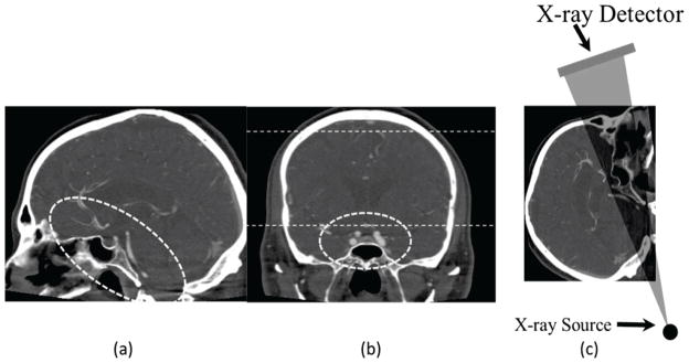
Sagittal (a) and Coronal (b) slices from a CT volume used to exemplify the location of the Circle of Willis, dotted straight lines in figure (b) indicate the area of lateral projection appropriate for the head equivalent phantom as recommended by the Report of AAPM Task Group 8. Figure (c) shows an arbitrary projection angle which includes part of the Circle of Willis.
Anthropomorphic head phantoms could be used to successfully reproduce x-ray imaging conditions specific to neuro-EIGI. However, evaluation of imaging quality characteristics such as resolution, low contrast detectability, etc. require a uniform head equivalent phantom. The AAPM9 recommends a lateral head equivalent uniform phantom, which is representative of the location between the dotted lines in Figure 1(b). It consists of a stack of the following plates: 2.5 cm acrylic, 2 mm Al, 10 cm acrylic, 1 mm Al and finally another 2.5 cm of acrylic. Such a phantom is not suitable to simulate frontal skull imaging, especially when the region of interest is the Circle of Willis. The purpose of the current project is to determine the materials needed to construct a uniform head equivalent phantom which could be used to evaluate imaging and exposure tasks specific to neuro-EIGI’s.
For phantom construction we chose acrylic for soft tissue and aluminum for the bone, which are in agreement with the AAPM9 and ICRU12 recommendations. Based on anatomical observations and previous phantom construction reports, 6, 10–12 we kept the acrylic amount for soft tissue equivalent identical with the AAPM recommendation, and reevaluated the bone equivalent aluminum thickness. As indicated by Conway et al.6 one approach could be to add additional sheets of aluminum to the phantom, until the automatic exposure of a x-ray system chooses identical parameters as those encountered during neuro-EIGI procedures.
We are proposing a different approach to find the bone equivalent for frontal imaging during neuro-EIGI. Different human skulls and an aluminum step wedge were imaged in identical x-ray exposure settings and a correlation between the gray values of the imaged skulls and those of the aluminum step thicknesses was established. A frontal-head equivalent phantom was constructed using the aluminum thickness with gray value equal to the average for the skulls found in the calibration process. The process was also done for the lateral view and the results compared with those obtained with the AAPM lateral head equivalent phantom9. Finally, the phantoms (AAPM lateral and new frontal) were x-ray imaged to evaluate the exposure parameters and the effects on the image quality factors, such as spatial resolution and low contrast detectability in fluoroscopy and DSA.
2. MATERIALS AND METHODS
This study contains three steps: evaluation of typical clinical neuro-EIGI x-ray parameters in a biplane angiographic suite, estimation of the aluminum thickness equivalent to frontal and lateral imaging of human skulls and, finally, assessment of imaging performance and exposure using the new frontal phantom equivalent.
Evaluation of x-ray exposure in clinical neuro-EIGI’s
We evaluated exposure parameters used for a number of neuro-endovascular image guided interventions (neuro-EIGI) in a clinical neuro-angiographic suite. The suite was equipped with a biplane x-ray image intensifier angiographic unit (To-shiba America Medical Systems, Tustin, CA). Fifteen cases were observed; they were performed in or distal to the Circle of Willis and included: arteriovenous malformation diagnosis, intracranial aneurysm treatment, and atherosclerosis diagnosis and treatment. The x-ray parameters selected by the automatic exposure rate control (AERC) were recorded for fluoroscopy and Digital Subtraction Angiography (DSA) for both imaging planes: frontal and lateral. The study was part of a clinical evaluation of the microangiographic fluoroscope (MAF)13, 14. The patients reported in this study signed an IRB consent. The technique parameters for sample runs with the conventional detectors used here may not be the same as those in a related but separate comparative study report by Wang et al.14
Estimation of the aluminum thickness equivalent to skull bone
Estimation of the aluminum thickness equivalent to skull bone was performed by imaging an aluminum step wedge and three human skulls in fluoroscopy and DSA modes using various kVp’s. They were imaged with a standard C-arm flat panel detector and the kVp settings were selected based on the clinical data observed in the first step. We set the kV between 80 and 100 for frontal view and between 70 kV and 90 kV for the lateral view, using 4kV increments. The kV settings and modalities were varied to evaluate the dependence of the phantom material thickness on the x-ray energy and beam filtration.
Acquisitions were made for 3 different frontal angulations of the C-arm: 250 caudal (CAU), 00 cranial (CRA) and 250 CRA. These orientations offer various views of the skull base and were used to determine if there were significant variations in the predicted Al thickness.
A LabVIEW program was developed to analyze the data. Each image used for analysis was obtained by averaging three acquired images. First, ROIs were drawn on each step of the aluminum wedge and the average gray value was then calculated. The aluminum step thickness was plotted versus the logarithm of the averaged gray value and the data was fitted with a 2nd degree polynomial function as seen in Figure 2. Such curves were derived for every x-ray parameter setting used to image the skull. These functions were then used to map the gray values from the acquired skull images to Al thickness in mm and an aluminum equivalent thickness map of the skull was calculated.
Figure 2.
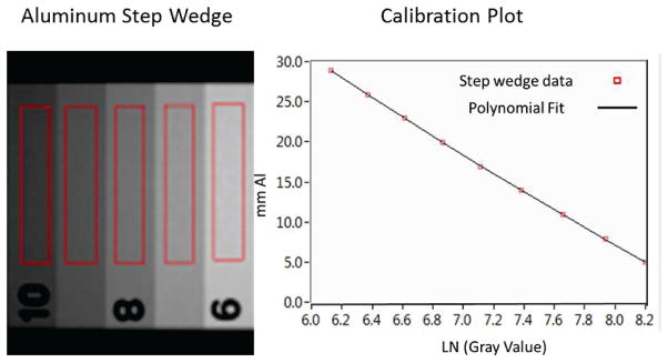
Sample image of the step wedge and the ROI’s used to calculate the average gray value. Example of a plot of aluminum thickness versus gray value and logarithmic fit; such curves were derived for every exposure setting.
To find the average aluminum thickness equivalent for frontal neuro-EIGI imaging, an ROI was drawn over the aluminum thickness equivalent map of the skull in a region overlapping the Circle of Willis. A histogram was calculated for the selected ROI and the average Al thickness and the standard deviation were calculated for each case and imaging settings.
To verify the accuracy of the method we took a calibration curve and estimated the aluminum thickness in a second step wedge, imaged under identical conditions. The results indicated accuracy within 5%.
Assessment of imaging performance and exposure
The frontal head equivalent phantom was built using the aluminum equivalent found in the previous section. The new phantom and the lateral head equivalent recommended by the AAPM in Report of Task Group 89 were imaged using Automatic Exposure Rate Control (AERC) with an angiographic C-arm. The parameters selected by the AERC were recorded and compared with the clinical results.
Effects on the image quality were evaluated by replacing the 3rd uniform acrylic plate with a standard NEMA XR21-20004 central plate in the middle of the head equivalent phantom. The plate is made of acrylic (Polymethyl methacrylate also referred as PMMA) and contains a resolution bar pattern, four iodine detail contrast targets (IDCTs), four air test pin cylinders and four lead test pins as seen in Figure 3(a). The IDCT’s contained four pairs of holes with diameters of 4, 3, 2, and 1 mm. Each set has different areal densities of iodine imbedded in epoxy: 20, 10, 5 and 2.5 mg/cm2. The features are located on one of plate surfaces. The plate was placed such that the features faced towards the top of the phantom. This setup places the structures virtually in the middle of the phantom.
Figure 3.
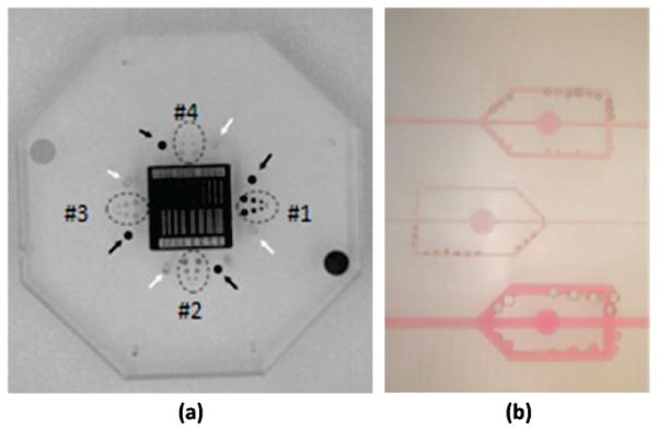
(a) central plates contains a resolution bar pattern, four iodine detail contrast targets (dotted ovals), four air test pin cylinders (white arrows) and four lead test pins (black arrows). (b) Nuclear Associates (Fluke Biomedical) simulated artery blocks 76–705
A second assessment was done using a simulated artery block phantom by Nuclear Associates (Fluke Biomedical), Stenosis/Aneurysm Artery Block 76–705 as depicted in Figure 3(b). The phantom was an acrylic block (15×45×2.5 cm) that contained three iodine–filled simulated arteries whose width and depth were 1, 2 and 4 mm. Each artery included simulated stenoses and aneurysms that are one-fourth, one half, and three-fourths of the artery’s width. The iodine concentration is 15 mg/ml. The module also has three circles 1 cm diameter, each with different iodine content (1.5, 3 and 6 mg/cm2) for testing linearity.
The artery block was inserted in a slot located in the middle of the head equivalent phantom as indicated previously by Ionita et al2. The setup allowed simulation of DSA by sliding the simulated arteries in the field of view once a mask was acquired. The arteries were situated at the end of the acrylic plate ensuring that the thickness of the phantoms was unchanged between the mask and simulated vessel image acquisition. On the subtracted images of the arteries we calculated the Signal to Noise Ratio (SNR) for each artery size for both frontal and lateral views. We calculated SNR as:
where Sa is the vessel signal, SBckg is the background signal and σBckg is the standard deviation of the background. Al values were estimated by selecting a small region of interest over the specified structures, generating a histogram and recording the peak values and the standard deviation.
For this study, we report observed differences between various measurements such as x-ray parameters or imaged structures, as percent errors. The percent errors are calculated as the absolute value of the difference between the compared values, divided by the reference value. When we compared any measurements with the clinical data, the clinical data was the reference value; when we compared uniform phantom data with the anthropomorphic phantom, the anthropomorphic phantom was the reference value. When we compare the proposed modified phantom with the AAPM lateral equivalent phantom data9, the AAPM phantom is the reference value. Finally, when we compared frontal plane with the lateral plane, the frontal plane is the reference value.
3. RESULTS
Evaluation of x-ray exposure in clinical Neuro-EIGI’s
Fifteen patients were evaluated; the exposure parameters selected by the system AERC are presented in Table 1. The selection included one AVM diagnosis, two stent assisted angioplasties, one balloon angioplasty, 11 aneurysm coiling, and diagnostic follow-ups. We recorded fluoroscopy and DSA parameters for both planes at the key moments of the treatments, most of the time they involved the highest magnification mode and placement or actuation of endovascular devices, pre and post treatment diagnosis. Four cases did not require usage of both imaging planes or modalities and data was not available (N/A).
Table 1.
Clinical Data Summary
| Frontal | Lateral | |||||||
|---|---|---|---|---|---|---|---|---|
| Fluoroscopy | DSA | Fluoroscopy | DSA | |||||
| Procedure Number | kVp | mAs | kVp | mAs | kVp | mAs | kVp | mAs |
| 1 | 71 | 0.67 | 85 | 11.2 | 70 | 0.45 | 85 | 7.4 |
| 2 | 96 | 0.67 | 85 | 29.8 | N/A | N/A | N/A | N/A |
| 3 | 107 | 0.67 | 106 | 24.3 | 76 | 0.67 | 97 | 12.5 |
| 4 | 110 | 0.67 | 85 | 29.8 | 83 | 0.67 | 85 | 10.1 |
| 5 | 91 | 0.67 | 85 | 31.4 | 77 | 0.67 | 85 | 9.7 |
| 6 | 80 | 0.67 | 85 | 28.3 | 70 | 0.67 | 85 | 11.1 |
| 7 | 87 | 0.67 | 97 | 27.2 | 77 | 0.67 | 110 | 10.0 |
| 8 | 74 | 0.67 | 85 | 27.5 | 73 | 0.67 | N/A | N/A |
| 9 | 77 | 0.67 | 85 | 23.3 | 72 | 0.67 | 97 | 9.6 |
| 10 | 76 | 0.67 | 110 | 12.8 | 70 | 0.60 | N/A | N/A |
| 11 | 110 | 0.65 | N/A | N/A | 81 | 0.67 | N/A | N/A |
| 12 | 82 | 0.67 | 85 | 32 | 70 | 0.54 | 106 | 9.5 |
| 13 | 88 | 0.67 | 85 | 28.2 | 70 | 0.54 | 97 | 8.2 |
| 14 | 80 | 0.67 | 97 | 21 | 70 | 0.67 | 85 | 12.3 |
| 15 | 85 | 0.67 | 85 | 27.5 | 80 | 0.67 | 108 | 10 |
| Average | 87.6±12 | .67±0 | 90±8.5 | 25.3±6.1 | 74±5 | .63±.07 | 95±9.6 | 10±1.45 |
The frontal DSA acquisitions with the x-ray mAs settings smaller than 16, used the small focal spot; for all the other the medium focal spot was used. The lateral plane used the small focal spot for all procedures and much smaller mAs’s than the frontal imaging plan; however the kVp settings were generally slightly larger except cases 3 and 14.
For fluoroscopy, the kVp settings were on average 15% larger for the frontal plane than the lateral, while the mAs settings were nearly the same. For DSA the kVp settings were 5% larger for the DSA but the mAs were 60 % larger.
Estimation of the aluminum thickness for skull bone equivalence
Experimental aluminum thickness maps are shown in Figure 4 for two different skull views (frontal and lateral). Such maps were derived for every skull, for three frontal angles and one lateral view and six kVp’s for both fluoroscopy and DSA. The field of view was selected to cover the bony area of the base of the skull where the Circle of Willis is located. Samples of the average aluminum thicknesses for the three different skulls at three different frontal C-arm orientations and two x-ray imaging modalities are shown in the first three plots of Figure 5. For a given angle and imaging modality the average Al thickness does not change with the x-ray kVp. The fourth plot in Figure 5 shows the same analysis for the lateral view in fluoroscopy for kVp’s selected within the range of the observed clinical data presented in Table 1.
Figure 4.

Aluminum thickness maps, for a frontal and lateral skull. The skull has some metal attachments not included in the average aluminum equivalent determination. The frontal map is focused on the area where the Circle of Willis is located, while the lateral shows the area for which the AAPM phantom is applicable.
Figure 5.
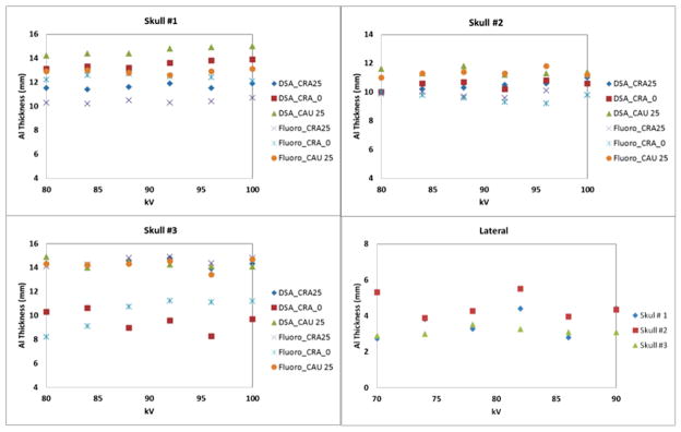
Average Aluminum thickness obtained using DSA and fluoroscopy for the frontal projection at different angles and using fluoroscopy for the lateral view.
The average aluminum equivalent thickness obtained for the frontal data was 12.7±2 mm. This result was obtained by averaging the data obtained from all the acquisitions for the three skulls. The variance between various C-arm orientations is less than 13% percent from the average. For skull 1 and 2 there was no significant systematic difference between the 00 CRA and the other orientations. For the 3rd skull we observed a systematic separation between the frontal and the 250 CRA or CAU views.
The system uses 0.3 mm copper filtration during fluoroscopy and 2.3 mm aluminum for the DSA runs. Despite different beam filtration there was no significant difference between the fluoroscopy and the DSA measurement results.
The lateral acquisitions indicated an average of 3.6 mm of Al for the bone equivalent which was 20% larger than the AAPM recommendation. The average thickness did not change significantly with the kVp.
Assessment of imaging performance and exposure
We replaced the 2mm Al thickness bottom plate and the top 1 mm plate of the AAPM lateral head9 recommended phantom with a 7 mm plate and a 6 mm plate respectively. The new frontal head equivalent phantom consisted of the following plates: 2.5 cm acrylic, 7 mm Al, 10 cm acrylic, 6 mm Al and 2.5 cm acrylic. The standard AAPM recommendation9 and the new neuro-EIGI frontal head-equivalent phantom were imaged and compared with an anthropomorphic phantom (RS-230, Supertech Elkhart, IN) imaged in the frontal and lateral views. Since the anthropomorphic phantom has large irregularities, we took four measurements for slight changes in the phantom location by moving the patient table and reported the data as an average ± standard deviation. The frontal changes were relatively small in order to contain the Circle of Willis in the center of the image. For the lateral views the shift were larger to cover various locations within white dotes line in Figure 1(b). The results are shown in Table 2.
Table 2.
Exposure setting summary
| Clinical Lateral | Clinical Frontal | Uniform Lateral Phantom (AAPM) | Uniform Frontal Phantom | Anthropomorphic Head Phantom (lateral) | Anthropomorphic Head Phantom (frontal) | ||
|---|---|---|---|---|---|---|---|
| Fluoroscopy | kVp | 74 | 87.6 | 80 | 84 | 82±4 | 84±2 |
| mAs | 0.63 | 0.67 | 0.42 | 0.67 | 0.35±0.09 | 0.67 | |
| μR/frame | - | - | 21 | 22 | 18±4 | 19±1 | |
| DSA | kVp | 95 | 90 | 88 | 88 | 85±4 | 88±1 |
| mAs | 10 | 25.3 | 14.3 | 26.5 | 13.3±1 | 24.7±0.5 | |
| μR/frame | - | - | 1466 | 1411 | 1300±180 | 1222±132 |
KVp settings comparison with the clinical data for frontal views (grey columns) of the anthropomorphic phantom and the new AP head equivalent agreed within 4% for fluoroscopy and 7% for the DSA. The mAs selection was nearly for fluoroscopy and DSA.
The lateral comparison of the clinical data, with AAPM recommended lateral head equivalent phantom9 and the anthropomorphic phantom is shown in Table 2 (white columns). The kVp selection comparison with the clinical data for lateral view (white columns) agreed within 11% for both fluoroscopy, and DSA. The mAs variation was within 44% for the fluoroscopy and 30% for the DSA.
The detector entrance exposure was reported for the experimental data only. The exposures obtained using the uniform phantoms, the AAPM lateral head9 and the new frontal head equivalent phantoms were compared with the anthropomorphic phantom. The difference in entrance exposures in fluoroscopy were less than 6% for both frontal and lateral phantoms. For the DSA, entrance exposures difference between the uniform phantoms and anthropomorphic phantom were within 13%.
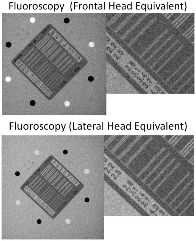
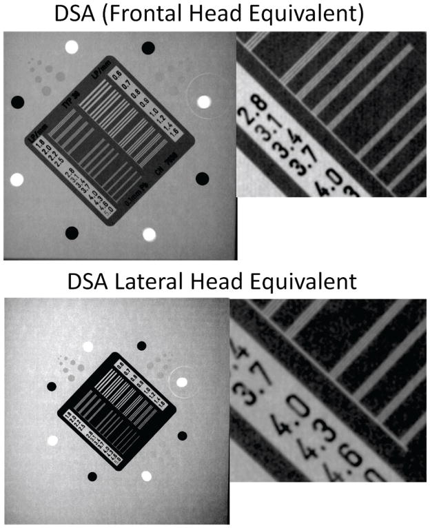
Figures 6, 7 and 8 show the results of imaging tasks using the frontal and lateral phantoms. For fluoroscopy 2.8 line pairs/mm are visible in the frontal phantom and 3.1 in the lateral one. For the DSA, 3.4 line pairs/mm are visible and 4 line pairs/mm for the lateral. The objects were magnified at the detector by a factor of 1.2.
Figure 6.
Fluoroscopy acquisition using a central NEMA plate placed in the middle of a head equivalent phantom
Figure 7.
DSA acquisition using a central NEMA plate placed in the middle of a head equivalent phantom
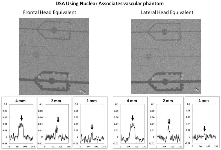
Figure 8.
DSA acquisition using a sliding simulated arterial block plate placed in the middle of a head equivalent phantom (top) and the corresponding relative line profiles for each simulated vessel (bottom)
The low contrast evaluation was done using the Iodine Detail Contrast Target (IDCT). In fluoroscopy (Figure 6) the first IDCT group was partially visible in the frontal phantom. In the lateral view the first group was fully visible while the second group was visible only partially. DSA runs (Figure 7) indicate that for the frontal phantom groups 1 and 2 (IDCT) were fully visible and the 3rd group was only partially visible, while for the lateral phantom the first three groups were fully visible and the fourth only partially visible.
DSA assessment using the simulated arterial block (Figure 8) showed that all three vessel complexes were visible. The line profiles were calculated by averaging three adjacent line profiles. We calculated the plotted lines by subtracting the background and then dividing the average line profile by the background average value. A more detailed analysis using the signal to noise calculation is shown in Table 3. The standard deviation of the noise was virtually identical: 2% of the background value for the lateral and 1% of the background for the frontal phantom. The system AERC selected a small focal spot for the lateral phantom and medium focal spot for the frontal phantom. The average of three adjacent line profiles for each of the vessels for each phantom is shown in Figure 8 (bottom).
Table 3.
Signal to Noise Ratio for simulated artery block in new frontal and AAPM lateral phantoms
| 4 mm | 2mm | 1mm | ||||
|---|---|---|---|---|---|---|
| Frontal | Lateral | Frontal | Lateral | Frontal | Lateral | |
| Signal Relative to the Background | 4% | 5% | 3% | 3.5% | 1.8% | 1% |
| SNR | 4 | 5 | 2.8 | 3 | 1.6 | 1 |
4. DISCUSSIONS
The study presented proposes a new frontal uniform head equivalent phantom suitable for neuro-EIGI procedures. During the clinical observations we noted a large discrepancy between the x-ray parameters selected by the system AERC and those predicted by the experiments using a lateral head equivalent phantom recommended by the AAPM Task Group 89. These facts triggered a reevaluation of the uniform phantom selection for neuro-EIGI’s. Clinical procedural settings and skull anatomical structure indicated insufficient bone equivalent material was being used in the phantom.
The amount of aluminum needed for a uniform frontal head equivalent phantom was calculated using real human skulls by correlating the grey values for the skulls with the thickness of an aluminum step wedge, previously imaged in identical x-ray conditions.
Our results indicated that the amount of aluminum needed to simulate imaging through the base of the skull is ~13 mm. For our calculations we selected three projection directions through the base of the skull in order to get additional views of the Circle of Willis area. The results did indicate some differences, which were of the same order as those observed between different skulls. The observed variability was about ± 2 mm or 13 % of the proposed value.
For a given skull bone equivalent measurement, the values did not change significantly with the change of the x-ray kVp indicating that the results are invariant with the beam energy. The change of the beam filtration when switching between fluoroscopy and DSA, did not show significant value changes in the average aluminum thickness estimation.
The lateral measurement using the same method indicated a somewhat larger amount of aluminum should be used to simulate the lateral projection when compared with the AAPM head recommendation; our data was closer to the value of 3.2 mm of Al proposed by Kyprianou et al. obtained after a limited number of measurements on cadavers.
Comparison of the x-ray selection parameters between the clinical data, the new uniform frontal head equivalent and an anthropomorphic phantom were within 7%, which is acceptable if we consider all the other variables such as x-ray equipment, human anatomy, calibrations etc. However, for the lateral phantom comparison, the differences were very large in both the kV’s and mAs. The result is understandable since the two parameters are changed in a programmed scheme by the x-ray AERC system to maintain a designated detector entrance exposure.
The last part of the study was concerned with assessment of the effects that inadequate phantom selection could have on system image quality evaluation and implicit system performance prediction. The bar pattern evaluation indicates a larger degradation of the resolution for the frontal phantom which may be the result of the system selection of the medium focal spot compared to the selection of the smaller focal spot for the lateral projection phantom. Low contrast detectability degradation could be explained by the increased beam hardening of the greater Al thickness.
The DSA measurements using the simulated vessels revealed insignificant degradation when using the frontal phantom. The medium and large vessel signal to noise ratio was slightly larger for the lateral phantom. For the smallest vessel pattern (1mm diameter) the data indicate larger SNR for the frontal phantom. The relative signal variations between frontal and lateral phantom, are nearly identical with the noise variance and the differences are too small to be statistically significant. The x-ray parameters for each acquisition are displayed in Table 2, and there was a 85% increase in the system mAs for the frontal when compared with the uniform lateral.
Despite limitations of the study, such as the number of skulls and the x-ray imaging systems used, our results indicate without doubt that the AAPM lateral head-equivalent phantom is not adequate for simulations or measurements specific to neuro endovascular image guided interventions.
5. CONCLUSIONS
The work presented shows the initial results toward developing a head equivalent phantom, which simulates the anatomy imaged during neuro-EIGI. During clinical investigations we found that technique predictions done using the AAPM recommended head equivalent9 were not accurate for neuro-EIGIs. To avoid errors and improve the imaging capabilities of both standard C-arm imagers and of a novel high resolution neuro imaging detector, the micro angiographic fluoroscope13, we determined experimentally the appropriate modification needed for the AAPM head phantom.
This study shows that significant bone simulating material needs to be added to the AAPM head equivalent phantom in order to enable it to be used for frontal neuro-EIGI applications.
Acknowledgments
This work was supported in part by NIH Grants R01-EB008425 and R01-EB002873 and equipment grants from Toshiba Medical Systems Corp.
References
- 1.Ionita C, Keleshis C, Jain A, Bednarek DR, Rudin S. Testing of the high-resolution roi micro-angio fluoroscope (maf) detector using a modified nema xr-21 phantom. Med Phys. 2009;36:2713. [Google Scholar]
- 2.Ionita CN, Dohatcu A, Jain A, Keleshis C, Hoffmann KR, Bednarek DR, Rudin S. Modification of the nema xr21-2000 cardiac phantom for testing of imaging systems used in endovascular image guided interventions. Proc SPIE. 2009;7258:72584R. doi: 10.1117/12.813533. [DOI] [PMC free article] [PubMed] [Google Scholar]
- 3.Kyprianou IS, Rudin S, Bednarek DR, Hoffmann KR. Generalizing the MTF and DQE to include x-ray scatter and focal spot unsharpness: Application to a new microangiographic system. Med Phys. 2005;32:613. doi: 10.1118/1.1844151. [DOI] [PubMed] [Google Scholar]
- 4.Balter S, Heupler FA, Lin PJ, Wondrow MH. A new tool for benchmarking cardiovascular fluoroscopes. Catheter Cardiovasc Interv. 2001;52:67–72. doi: 10.1002/1522-726x(200101)52:1<67::aid-ccd1016>3.0.co;2-l. [DOI] [PubMed] [Google Scholar]
- 5.Compagnone G, Pagan L, Bergamini C. Comparison of six phantoms for entrance skin dose evaluation in 11 standard x-ray examinations. J Appl Clin Med Phys. 2005;6:101–113. doi: 10.1120/jacmp.v6i1.2020. [DOI] [PMC free article] [PubMed] [Google Scholar]
- 6.Conwayk BJ, Duff JE, Fewell TR, Jennings RJ, Rothenberg LN, Fleischman RC. A patient-equivalent attenuation phantom for estimating patient exposures from automatic exposure controlled x-ray examinations of the abdomen and lumbo-sacral spine. Med Phys. 1990;17:448–453. doi: 10.1118/1.596483. [DOI] [PubMed] [Google Scholar]
- 7.Havukainen R, Pirinen M. Patient dose and image quality in five standard x-ray examinations. Med Phys. 1993;20:813–817. doi: 10.1118/1.596987. [DOI] [PubMed] [Google Scholar]
- 8.Maynard H, Lin PP, Olson A, Rothenberg L, Rutz L, Shapiro G, Shaw C, Wagner L. Report of digital radiography/fluorography task group, diagnostic x-ray imaging committee, performance evaluation and quality assurance in digital subtraction angiography, AAPM Report No 15. American Institute of Physics; 1985. [Google Scholar]
- 9.Chu RYL, Fischer J, Archer BR, Conway BJ, Goodsitt MM, Glaze S, Gray JE, Strauss KJ. Report of task group 8, diagnostic x-ray imaging committee, standardized methods for measuring diagnostic x-ray exposures, AAPM Report No 31. American Institute of Physics; 1990. [Google Scholar]
- 10.Rea JA, Blake GM, Fogelman I. Development of a phantom for morphometric x-ray absorptiometry. British Journal of Radiology. 2001;74:341–350. doi: 10.1259/bjr.74.880.740341. [DOI] [PubMed] [Google Scholar]
- 11.Steel SA, Thorpe JA, Walker R, Howey S, Langton CM. Development and evaluation of a phantom for morphometric x-ray absorptiometry. Osteoporosis International. 1999;9:38–44. doi: 10.1007/s001980050114. [DOI] [PubMed] [Google Scholar]
- 12.Jones AK, Hintenlang DE, Bolch WE. Tissue-equivalent materials for construction of tomographic dosimetry hantoms in pediatric radiology. Med Phys. 2003;30:2072–2081. doi: 10.1118/1.1592641. [DOI] [PubMed] [Google Scholar]
- 13.Binning MJ, Orion D, Yashar P, Webb S, Ionita CN, Jain A, Rudin S, Hopkins LN, Siddiqui AH, Levy EI. Use of the microangiographic fluoroscope for coiling of intracranial aneurysms. Neurosurgery. 2011;69:1131–1138. doi: 10.1227/NEU.0b013e3182299814. [DOI] [PMC free article] [PubMed] [Google Scholar]
- 14.Wang W, Ionita CN, Huang Y, Qu B, Panse AS, Jain A, Bednarek DR, Rudin S. Region-of-interest micro-angiographic fluoroscope detector used in aneurysm and artery stenosis diagnoses and treatment. Proc SPIE 8313. 2012 doi: 10.1117/12.910771. in print. [DOI] [PMC free article] [PubMed] [Google Scholar]


