Abstract
Fourteen explanted Dynesys® spinal devices were analyzed for biostability and compared with a reference, never implanted, control. Both poly(carbonate-urethane) (PCU) spacers and polyethylene-terephthalate (PET) cords were analyzed. The effect of implantation was evaluated through the observation of physical alterations of the device surfaces, evaluation of the chemical degradation and fluids absorption on the devices and examination of the morphological and mechanical features. PCU spacers exhibited a variety of surface damage mechanisms, the most significant being abrasion and localized, microscopic surface cracks. Evidence of oxidation and chain scission were detected on PCU spacers ATR–FTIR. ATR–FTIR, DSC and hardness measurements also showed a slight heterogeneity in the composition of PCU. The extraction carried out on the PCU spacers revealed the presence of extractable polycarbonate segments. One spacer and all PET cords visually exhibited the presence of adherent biological material (proteins), confirmed by the ATR–FTIR results. GC/MS analyses of the extracts from PET cords revealed the presence of biological fluids residues, mainly cholesterol derivatives and fatty acids, probably trapped into the fiber network. No further chemical alterations were observed on the PET cords.
Although the observed physical and chemical damage can be considered superficial, greater attention must be paid to the chemical degradation mechanisms of PCU and to the effect of byproducts on the body.
Keywords: Polycarbonate urethane, In vivo degradation, FTIR, DSC
1. Introduction
Segmented polyurethane elastomers have been used in several biomedical applications in recent decades, thanks to the combination of excellent biocompatibility and mechanical properties. Polyurethane (PU) elastomers are block copolymers based on polyurethane as hard segment and on polyols as soft segment. The term ‘polyols’ in general identifies aliphatic macrodiols with ester, ether or carbonate groups in the main chain [1]. The first generation of PU biomaterials, represented by polyester urethanes, easily underwent hydrolysis, being then unsuitable for long term implantation [2,3]. Hydrolysis of the ester linkage produces acid groups which increase the acidity surrounding the degrading polyurethane and may autocatalyze the degradation. The second generation, polyether urethanes, showed a higher stability to hydrolytic degradation, but a susceptibility for oxidative degradation [4]. Polycarbonate urethanes (PCUs) were identified as substitutes for the first and second-generation polyurethanes and were introduced in the 1990s as a third generation of thermoplastic elastomers for biomedical applications [2]. PCUs showed a higher biostability and superior performance, in respect to the other generation of polyurethanes [5–7], thanks to the presence of the carbonate group in the main chain of the soft segment.
PUs are characterized by a two-phase morphology. The hard and soft segments of the polyurethane copolymer are immiscible and undergo segregation. Consequently, the morphology of PUs is characterized by an amorphous matrix containing both disorganized hard and soft segments, as well as hard micro-domains dispersed in the matrix[8]. These hard micro-domains consist of hard segments organized in a three dimensional network of hydrogen bonding and act as physical crosslinks. The microphase separation is responsible for unique physical properties of PCUs that allow a broad range of applications [9].
Previous in vitro studies have demonstrated that the morphology of PCU is influenced by the experimental conditioning that induces a morphological reorganization [10–12]. Moreover, in vitro studies showed that both composition and morphology have a role in the biostability and biocompatibility as well as an effect on biodegradation [13–15]. In particular, the extent of phase separation has an influence on the cell attachment and proliferation [16,17]. Previous studies on PCU have also indicated a higher resistance to hydrolysis, environmental stress cracking (ESC), metal ion oxidation (MIO) and calcification, with respect to polyether urethanes [18]. Even if evidence of chemical and physical degradation was observed during in vitro and in vivo studie[10,19–21], segmented polyurethanes based on polycarbonate are more stable toward oxidative degradation than polyurethane with a polyether soft segment [5,20].
The chemical degradation of both polyether and polycarbonate urethanes was referred to as oxidative degradation, and it was related to chain scission and/or crosslinking of the copolymer [22], mostly involving the soft segment. Enzymatic studies on PCU show that hydrolytic enzymatic degradation with cholesterol esterase, an enzyme over expressed in inflammatory system, is negligible [23], but the cleavage of the urethane bond was observed [24,25] and the formation of methylene dianiline was detected [26].
Although PCUs have been widely studied in cardiovascular applications [7,21] relatively few studies have examined the response of PCU to human implantation under load-bearing applications, such as orthopedic and spinal implants, which makes these observations of particular interest to the in vivo-degradation field. Simulator studies and retrieval observations performed on PCU show a lower wear rate, a lower particle generation rate and a larger sizes for particles, compared with the other polymeric and metal systems, indicating a promising wear performance and a low osteolytic potential [27,28].
Dynesys® Dynamic Stabilization System is a multi-component device developed for treatment of the lumbar spine pain, manufactured by Zimmer Spine [29]. Dynesys is used internationally mainly for non-fusion treatment of the lumbar spine [30]. In the United States, Dynesys has been cleared by the FDA for lumbar fusion, but is currently not approved for spinal stabilization without fusion. The Dynesys® System is composed of pedicle screws, PCU spacers and a cord. The screws are made of a titanium alloy (Ti6Al7Nb) and anchor the system to the spine through the pedicles. The polyethylene-terephthalate (PET) cord connects the screws and limits spinal flexion. The hollow spacer, molded from polycarbonate urethane (PCU), surrounds the cord between the screws and limits spinal extension.
The biostability evaluation of polyesters has shown excellent properties and resistance to microbial attack for the aromatic polyester, especially for PET [31]. Biodegradation of PET fibers to a small extent was detected on the terminal ester, but it was found to be more prominent above the glass transition temperature (about 70 °C) [32,33], thus far from implantation condition.
Previous researches on the Dynesys® System analyzed the biostability of the explanted components: PCU spacer and PET cord. In one study [34], changes in the distribution of molecular mass and in the chemistry composition of the block copolymer were not observed, then absence of biodegradation was assumed. In another study name[35], the explanted devices showed permanent deformation, wear and surface damage. Chemical changes were also observed and associated to a general indication of biodegradation.
In the present work, some of the samples collected in the latter study [35], were further analyzed in detail in order to better elucidate the physical and chemical changes on both PCU spacer and PET cord. In particular, in this paper, the chemical changes observed on the devices surface using ATR–FTIR were specifically correlated to in vivo exposure. Additional considerations are made about composition and morphology of the devices, matching up the bulk and surface features. Moreover, the identification of the products extractable from the implanted devices is a necessary starting point in the study of body/devices interactions.
2. Materials and methods
2.1. Materials
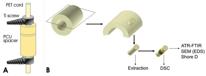
Fourteen explanted Dynesys® devices and one exemplar (not implanted) were tested. A schematic drawing of the overall Dynesys® device is showed in Fig. 1A. The PCU spacer is based on a soft polycarbonate segment and on an aromatic polyurethane hard segment (Bionate® 55D, DSM-PTG [36]). Previous literature studies reported an average Mw around 150,000–200,000 g/mol for this material [34]. The Dynesys® spacer has a thickness of 3.6 mm and an external diameter of 12 mm. It has a circular track at 2.5 mm from the upper end. The spacer length depends on the site of implant in the spine (see Ref. [29] for a more accurate scheme of the whole system). Before the implantation the spacer is cut, then located and locked with the other components of the system. Due to this procedure, each spacer is characterized by two different ends, one of which is cut and the other, which is molded. The spacer lengths of the analyzed prostheses range from 5 mm to 21 mm.
Fig. 1.
Schematic representation of the Dynesys system (A) and of sample preparation (B).
The PET cord of the Dynesys® system is a network of microfibers of 25 μm diameter. The length of the cord depends on the number of consecutive spacer and the diameter is 4 mm. The average Mw of the PET fibers in a similar system was reported to be around 75,000 g/mol [34].
The implantation time of the Dynesys® devices ranged from 0.7 to 6.5 years of implantation. More details for each specimen, along with a short description of macroscopic observations, are reported in Table 1.
Table 1.
Summary of patients and implant data of the fifteen Dynesys® retrieval considered.
| Sample | Age/sex | Years implanted |
Observation |
|---|---|---|---|
| 1 – Exemplar | – | – | Not implanted, used as reference |
| 2 – Dyn 002 | 45 – M | 0.7 | Crushed on one side |
| 3 – Dyn 003 | 50 – M | 1.0 | Bent |
| 4 – Dyn 004 | 44 – Uk | 1.1 | – |
| 5 – Dyn 005 | 49 – F | 2.5 | Both ends cut |
| 6 – Dyn 006 | 48 – F | 1.9 | Wrong cut |
| 7 – Dyn 008 | 32 – M | 1.0 | Deep erosion |
| 8 – Dyn 009 | 44 – F | 2.4 | Crushed on one side |
| 9 – Dyn 010 | 37 – M | 4.0 | Extended opacization |
| 10 – Dyn 012 | 30 – F | 6.5 | – |
| 11 – Dyn 013 | 47 – M | 2.9 | Bent |
| 12 – Dyn 014 | 40 – F | 2.4 | – |
| 13 – Dyn 015 | 47 – M | 2.2 | Crushed on one side and bent |
| 14 – Dyn 019 | 54 – M | 5.2 | Crushed on one side |
| 15 – Dyn 020 | Unknown | Unknown | Half glossy and half opaque |
Reasons for revision were not related to failure or rupture of the PCU or PET components. For most cases, the primary diagnosis was disc degeneration and the revision reasons were persistent back and/or leg pain and screw loosening [35].
2.2. Sample preparation
Explanted spacers and cords were cleaned with an antimicrobial hand-wash and demineralized water, in order to remove a broader spectrum of microorganisms.
After cleaning, each PCU spacer was cut in half and the two sections were stored in the dark at room temperature. One section was used to perform bulk and surface analyses: circular punches, on which the measurements were performed, were cut from the device as shown in the simplified scheme reported in Fig. 1B.
The manipulation during surgery, cut or partial alteration of the cord, reduces the possibility to distinguish the effects of implantation from the surgeon action. Nevertheless the PET cord was cut and analyzed, considering both internal and external fibers, with particular attention to the most altered segments.
2.3. Physical and chemical characterization
The retrieved Dynesys® Systems, spacers and cords, were examined macroscopically and microscopically. A microscope with an integrated digital camera (Leica EZ4D) was used to examine the sample and to take magnifications of the surface. The surface was observed by scanning electron microscopy (SEM; Leica Stereoscan 410, Oxford Instrument) on gold-coated samples. When necessary, SEM instrument equipped with an EDS microprobe (energy dispersion spectroscopy; Oxford Link ISIS) was also used to investigate the chemical composition.
ATR–FTIR spectroscopy has been used to study the surfaces of the devices and to investigate the chemical changes occurred during implantation. ATR–FTIR spectra of the device surfaces were recorded on FT-IR spectrometer (Perkine–Elmer, Spectrum 100) in the attenuated total reflectance (ATR) mode with a diamond crystal, using 16 scans per spectrum and a resolution of 4 cm−1. At least five spectra were recorded on different zones of each device. The infrared spectra were collected on the inner and on the outer surface of the prostheses, as well on the molded and on the cut end of the devices. Regions with macroscopic alteration of the surface were preferably analyzed.
In order to evaluate the presence of adsorbed species, the punches of the prosthetic samples and part of the cords were extracted with cyclohexane (at 60 °C for 24 h). After the extraction, the prosthetic samples were dried off and ATR–FTIR spectra of the surface were collected. The extracted solutions were concentrated and injected in the gas chromatography-mass spectrometry system (6890N Network GC System coupled to a 5973 Network MASS Selective Detector; Agilent Technologies, USA), equipped with a methyl-phenyl-polysiloxane cross-linked 5% phenyl methyl silicone capillary column (30 m, 250 μm i.d., 0.25 μm film thickness). The temperature of the inlet was kept at 280 °C. The carrier gas was helium (1 ml/min) and spit ratio was 1/40 of the total flow. The temperature program was: 70 °C for 1 min, then a ramp with a heating rate 10 °C/min to 320 °C and held for 10 min. Mass spectra were recorded after 2.50 min of solvent delay, under electron impact at 70 eV and using the scan range 11–500 m/z. NBS75K and Wiley138 libraries were used to identify products with a score of more than 95%.
In order to evaluate the bulk morphology of the spacers, differential scanning calorimetry (DSC Q200, TA Inc.) was used to detect characteristic thermal transitions and to investigate the degree of micro-phase separation in the samples [37,38]. The DSC measurements were performed on about 10 mg sample, with open aluminum pan under nitrogen atmosphere (50 cm3/min) and with a 20 °C/min heating rate, from –75 °C up to 200 °C cyclically. The use of 200 °C as top temperature was selected considering that the thermal degradation of this PCU starts around 230 °C [39].
The Shore Hardness Test was used to assess the hardness of PCU spacer, the durometer was utilized with a specific indenter shapes and spring loads for Shore D scale.
3. Results and discussion
3.1. Macroscopic observation
6/14 explanted devices exhibited a permanent deformation of the cylindrical spacer (see Table 1). In three cases (Dyn 3, Dyn 13 and Dyn 15), the cylinder is characterized by bending ranging from 8 to 12°. Besides, the circular track of four spacers (Dyn 2, Dyn 9, Dyn 15 and Dyn 19) results compressed on one side, but the overall shape of the spacers remained undeformed, with the exception of Dyn 15. These two behaviors indicate an incomplete recovery (creep) of the original shape after a continuous mechanical loading. Permanent deformation was not significantly correlated with spacer length and with implantation time. Information on the patients such as body weight and activity level were not known. However, it was noted that almost all the deformed spacers (5/6) were observed on devices implanted in male patients.
Both the exemplar and all the retrieved spacer components exhibited a slight yellowing with respect to the uncolored virgin material. This discoloration, although common in polyurethane-based manufactures, clearly indicates a chemical modification induced during processing. It was previously shown [39] that the temperature needed to create a homogenous melt is close to the temperature at which thermal degradation starts.
In most cases, the external surface of the devices was mainly smooth and glossy. In some cases, limited or extensive opaque areas were identified. In particular, one spacer (Dyn 20) demonstrated a diffuse opacification on one whole side, while another device (Dyn 10) showed an extended whitening diffused to all the spacer.
The PET cords also showed residual effects of the implantation. A diffuse yellowing of the implanted fibers is attributed to biologic residues, due to contact with body fluids.
3.2. Microscopic observation
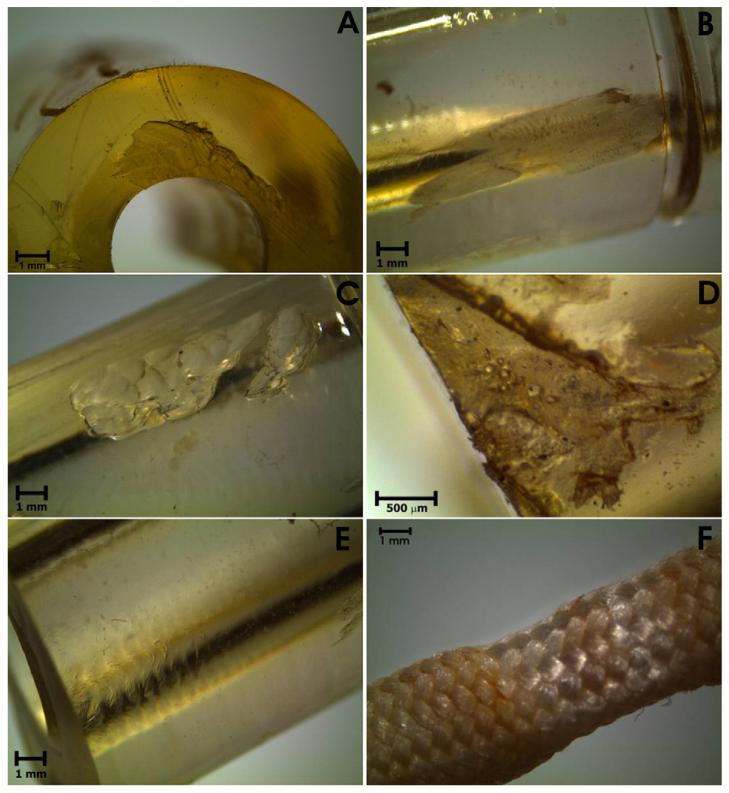
At a microscope inspection, the spacers exhibited a variety of surface damages, summarized in Fig. 2, likely due to different causes. Commonly observed superficial damage include small cuts and scratches along the spacers, which were mostly attributed to the surgical removal, since the features of the scratches can be connected with scalpel marks; in one case a small crack, in another case a fracture were also observed on the molded end. A circular mark and superficial erosion at the end of the spacer were present in most spacers, an example is showed in Fig. 2A. They were attributed to the imprint of the pedicle screw head.
Fig. 2.
Micrographs of the most representative alteration of the PCU spacers (A–E) and PET cords (F).
The loss of glossy and smoothness can be attributed to impingement with bone, due to abrasive wear, or to a visible action of biodegradation on the surface. The most representative images of both these phenomena are reported in Fig. 2B–C and D respectively. Imprints on the inner wall of the devices, indicating plastic deformation due to the contact with the cord, were also frequently observed (Fig. 2E). Also the cord is characterized by plastic deformation, in the segment where the screws anchor the device to the spine. In this zone, the fibers are less yellowed (visible in web version) and the braided network results compressed, as it is showed in Fig. 2F.
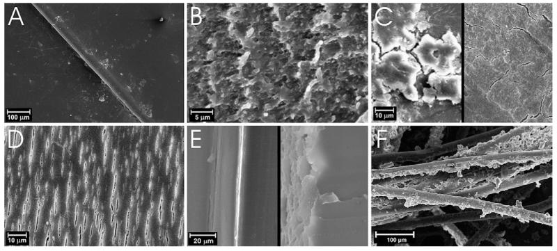
After visual and optical microscope inspection, SEM images were taken from the most attractive zones and samples. The most interesting observations are reported in Fig. 3. The undegraded surfaces of the retrievals, as that of the exemplar, show a smooth surface (Fig. 3A).
Fig. 3.
SEM images of the most representative microscopic alteration observed on PCU spacers (A–E) and PET cords (F).
The zones of the surface that appeared opaque at the optical microscope, exhibit various form of alterations when inspected with SEM. The surfaces characterized by an evident eroded and opaque region, as visible in Fig. 2B–C, show a typical abrasive wear pattern (Fig. 3B), characterized by a rubber like behavior. One of the most interesting sample (Dyn 10) showed a surface that looks inhomogeneous at unaided-eyes, with an alternation of lighter and darker areas at the optical microscope. The lighter and darker zones look, in the SEM images, reported in Fig. 3C (left), like a succession of smooth surface and attached micro-aggregates. Branched fissures were also observed on this device, as it is showed in Fig. 3C (right), more emphasized near the micro-aggregates. Branched fissures can be attributed to environmental stress cracking (ESC), a result of residual polymer surface stress, which may be introduced during fabrication of the device and not sufficiently reduced by annealing. The contact with human fluids may speed up this phenomenon, because of the absorption/desorption of species [40].
In 2/5 observed samples, aligned fissures or microscopic surface cracks were detected (Fig. 3D). The opaque side of Dyn 20 was characterized by aligned fissures extended to a large area of the surface. On restricted zones, erosion and presence of micro-aggregates were observed in addition to the fissures. These results indicate that the devices were subjected to a degradation phenomenon involving crack formation and propagation, due to the ESC on PCU. Being aligned perpendicularly to the applied load, the fissures may be attributed to fatigue stress [41]. No correlation was found between aligned fissures and shape deformation. Further, the appearance of these microscopic cracks did not show any correlation with the sample height and with the implantation time.
To investigate how deep these surface alterations propagate, Exemplar and Dyn 10 devices were observed in section and their comparison is shown in Fig. 3E. The edge of the Exemplar (left) is completely smooth, while the edge of Dyn 10 (right) is jagged, due to the cracks. This alteration involves no more than the first 10 μm of the surface, suggesting no influence on the mechanical properties of the entire device.
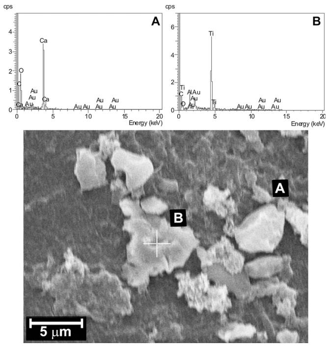
Some explanted spacers were characterized by occasional adherent surface deposits that had resisted the washing procedure, on both the external and internal surfaces of the device. The adherent surface deposits were analyzed by EDS and the most representative results are showed in Fig. 4. They are in some cases calcifications (Fig. 4A), due to the deposition of calcium-containing species [42]; in most cases, where no metal signals were detected, the surface deposits were attributed to organic depositions, such as biological species. The extended micro-aggregates present on the surface of Dyn 10 and described previously were organic in composition. In one case, a piece of broken screw was also revealed (Fig. 4B) on the inner surface of the spacer.
Fig. 4.
SEM image and EDS results of micro-aggregates observed on the surface of PCU spacers.
Micro-aggregates, characterized by an organic composition, were observed also on the fibers of the PET cord, mainly on the external fibers, directly exposed to the body fluids, as it can be seen in Fig. 3F.
3.3. Surface chemical characterization
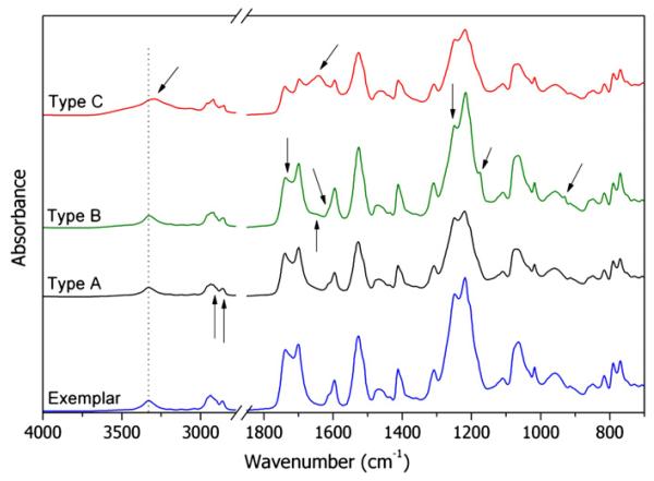
Table 2 reports the frequencies and relative assignments of the main FTIR signals of PCU [7,9], while the ATR–FTIR spectrum of the reference, unimplanted sample is shown in Fig. 5 (Exemplar).
Table 2.
FTIR absorbance peaks assignments of PCU.
| Wavenumber (cm−1) | Assignment |
|---|---|
| 3334 | N–H stretching (free and H-bonded) |
| 2956, 2938, 2900, 2862 | CH2 asymmetric and symmetric stretching |
| 1738–1700 | C=O stretching urethane and carbonate (free and H-bonded) |
| 1597 (1613 sh) | C=C stretching in aromatic ring |
| 1526 | N–H bending + C–N stretching |
| 1466 | CH2 bending |
| 1412 | C–C stretching in aromatic ring |
| 1308 | N–H bending + C–N stretching, C–H bending out of plane |
| 1246 | O–C–O stretching carbonate |
| 1219 | O–C–N stretching urethane |
| 1110 | C–C–O stretching carbonate |
| 1070 | CO–O stretching urethane |
| 1018 | C–H bending in plane aromatic ring |
| 953 | O–C–O stretching carbonate |
| 816 | C–H bending out of plane aromatic ring |
| 790 | O–CO–O bending out of plane carbonate |
| 770 | O–CO–N bending out of plane urethane |
Fig. 5.
FTIR spectrum recorded on the reference PCU sample (Exemplar) and FTIR spectra of the most common alterations detected on the explanted spacers.
PCUs are characterized by two different carbonyl groups, from the carbonate and urethane segments respectively, that result in closed signals centered at 1738–1700 cm−1, at 1246–1219 cm−1 and at 790–770 cm−1 in the infrared spectra. Both groups may be involved in hydrogen bonds, resulting into a total of five different carbonyl FTIR vibrations in the range 1738–1700 cm−1. In the ATR–FTIR spectrum, multiple signals, resulting from the overlapping of the mentioned absorptions, can be detected: a signal at 1700 cm−1 has been attributed to strongly hydrogen-bonded carbonyls of the urethane group in the ordered hard domains; a multiple shoulder at 1722 cm−1 to hydrogen-bonded carbonyls of both carbonate and urethane groups in the amorphous phase, while the broad signal centered at 1737 cm−1 has been assigned to free (not involved in hydrogen bonding) carbonyls of the carbonate and urethane groups[39,43,44].
The relative intensity of these signals can be correlated to the composition of the polyurethanes as well as to the micro-phase separation and this feature has been often used to gain information on the phase morphology of segmented PUs [45,46]. Nevertheless, in analyzing the ATR–FTIR spectra of the retrievals, we were unable to separate the effects of different phase morphology in the pristine copolymer from that of chemical degradation occurred in vivo. Therefore, we mainly concentrated on changes attributable to degradation, leaving most considerations on differences in morphology to the DSC analyses of the bulk material.
However, it is worth mentioning that some differences were always detected in the carbonyl region between the spectra recorded on the molded or on the cut end of the same spacer. It is well known that the phase morphology of segmented PUs is highly sensitive to mechanical stresses [47], therefore the observed differences were attributed to an incomplete recovery of the cut stresses induced at the implant.
Moreover, in 4/14 sample (Dyn 5, Dyn 9, Dyn 14 and Dyn 15), the relative intensities of the H-bonded carbonyl and free carbonyl signals are significantly different from that of the exemplar and of the majority of the samples. This suggest a different morphological organization and probably a different composition.
It is important to point out that the changes in the signals were variable among different zones of the same sample. Altered spectra were often obtained from visually altered areas.
The examination of all the retrieved spacers lead to the identification of three main patterns of alteration of the infrared spectrum. One example for each kind of alteration is shown in Fig. 5 (the curves are labeled Type A, B, C).
The first kind of alteration (Type A) consists in the presence of two new signals at 2920 and 2850 cm−1, attributed to C–H stretching of new alkyl species. To better understand the origin of these signals, punched samples were extracted in hot cyclohexane for 24 h. The spectra of the extracted samples did not show the same signals. Since the absorption of body fluids components is commonly observed into retrieved prostheses [48], these signals can be attributed to the presence of aliphatic long chain hydro-carbons, probably fatty acids, diffused into the device during in vivo time and extracted with the organic solvent. Nevertheless, being the absorption quite weak, and given the multiple manipulation steps occurred after retrieval, at this stage we cannot exclude that the presence of fatty acids might be related to accidental contamination.
Type A alteration was detected in all the device. In 7/14 spacer only this change was observed, while all the other IR signals were unchanged.
6/14 spacers exhibit an ATR–FTIR spectrum similar to that reported in Fig. 5 (Type B). The appearance of two new absorption at 1175 and 930 cm−1 is related in the literature to the oxidative degradation of the PCU [22,49]. The increase of the new signals is strictly connected to a change in the shape of the signal at 1600 cm−1 and to disappearance of the shoulder at 1614 cm−1. For high levels of oxidation a new, low signal was detected at 1645 cm−1. The change in the phenyl signal indicates a mechanism of oxidative degradation that involves the urethane segment.
In addition, in the most degraded samples, the absorption at 1736, 1248 and 790 cm−1 show a dramatic decrease, if compared to those at 1700, 1219 and 770 respectively. The decrease of all the signals related to the carbonyl groups of carbonate species suggests a decrease in the amount of carbonate segments, indicating also an involvement of carbonate species in the degradation mechanism.
A degradation mechanism involving chain scission in the carbonate segments was already hypothesized by an in vitro oxidation study performed on PCU [22]. In literature, the presence of the new signals at 1175 cm−1 was often attributed to the formation of crosslinks between the polyol segments during in vivo and in vitro oxidation [22,49]. Nevertheless, other literature studies suggest that it may also involve the polyurethane segments and, in particular, the reactivity of groups closed to the aromatic structures[50–52]. The results obtained in this work confirm the involvement of both segments in the oxidative degradation mechanism.
The level of oxidative degradation was not significantly correlated to the implantation time of the device, suggesting a multifactorial oxidation path that must involve other parameters, besides the simple time of exposure to in vivo environment. One most evident factor is the environmental stress cracking (ESC), since oxidation was mainly detected in the abraded or cracked zone, indicating that mechanical load and wear have an influence on surface oxidation. However oxidized surfaces were detected also in zones that appeared homogenous, suggesting a complex degradation process possibly started before implantation and accelerated by the in-vivo environment.
In order to verify if also the bulk material below the surface was affected by the observed degradation, cross-sections cut from the spacers were also analyzed. Series of micro ATR–FTIR spectra were collected on the sections, every 100 mm starting from the external surface towards the bulk. All the spectra recorded, even on the first 100 mm below the surface, showed no changes compared to control, indicating that significant chemical changes are confined to the surface.
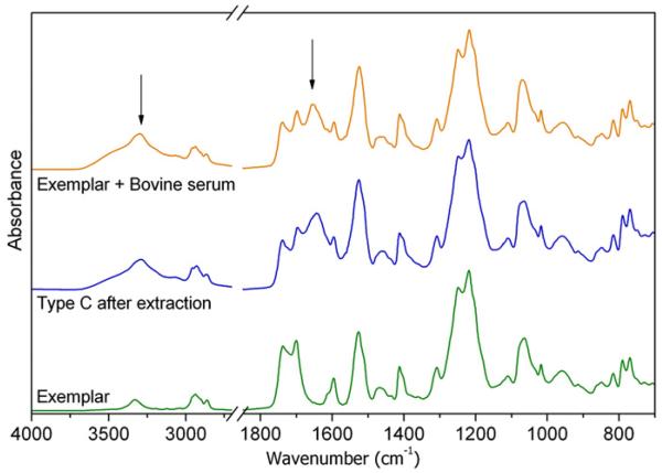
2/14 samples and especially Dyn 10, which exhibited extended attached micro-aggregates in the SEM images, showed Type C alteration: two new, strong signals appeared at 3285 cm−1 and 1638 cm−1. The comparison of both the micrographs and the spectra of the surface before and after extraction revealed that the species responsible for the new absorptions cannot be removed by cyclohexane extraction. We hypothesized that the new signals may be due to proteins and protein-like substances [53], coming from body fluids and strongly adsorbed on the surface. In order to simulate the biological environment, a fragment of the exemplar sample was kept into bovine serum for three days. The comparison reported in Fig. 6 between the spectrum of the retrieved spacer and that of the specimen soaked into bovine serum seems to confirm our hypothesis. The difficulty of completely removing all such adhering tissue without modifying the surface properties is a known problem. Traditional cleaning methods may cause the tissue to become tightly attached to the structure of the prosthesis, but a more aggressive cleaning treatments may affect the chemical, physical and morphological properties of the prosthetic material [54].
Fig. 6.
Comparison of ATR–FTIR spectra of the exemplar with that of a retrieved sample and that of the exemplar soaked into bovine serum.
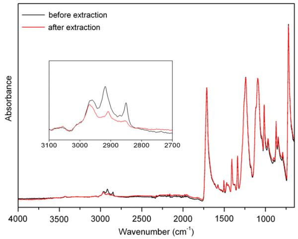
The FTIR absorption characteristic of PET are listed in Table 3 [55,56]. In the ATR–FTIR spectra of our retrieved PET cords, very strong additional signals in the CH2 stretching region, in particular at 2920 and 2850 cm−1, are observed, as for the PCU spacers. Again, after cyclohexane extraction, these signals disappeared. The spectra recorded before and after extraction are compared in Fig. 7. In some cases additional signals at 1638 cm−1 and 3285 cm−1 were detected, referred also in this case to biological species adsorbed on the surface, probably proteins. This is an additional confirmation of the organic origin of the micro-aggregates observed in the SEM images reported in Fig. 3F. No other changes in the infrared pattern were detected attributable to degradation, confirming the PET biostability.
Table 3.
FTIR absorbance peaks assignments of PET.
| Wavenumber (cm−1) | Assignment |
|---|---|
| 2960, 2919, 2849 | CH2 asymmetric and symmetric stretching |
| 1712 | C=O stretching ester |
| 1579, 1505 | C=C stretching aromatic ring |
| 1471, 1453 | CH2 bending |
| 1408 | C–C stretching aromatic ring |
| 1385 (sh) | CH2 deformation |
| 1371 (sh), 1339 | CH2 wagging |
| 1240 | CO–O stretching ester |
| 1175 (sh) | C–H bending in plane aromatic ring |
| 1117 (sh) | Skeletal vibration aromatic ring |
| 1095, 1044 (sh) | O–CH2 stretching |
| 1017 | C–H bending in plane aromatic ring |
| 970 | C–O stretching ester |
| 896 | CH2 rocking |
| 872, 846 | C–H wagging/bending aromatic ring |
| 791 | CO–O bending out of plane ester |
| 721 | COO wagging out of plane + C–H wagging |
| aromatic ring + CH2 Rocking |
Fig. 7.
Comparison of ATR–FTIR spectra of PET cords before and after extraction.
3.4. Analyses of the extracts
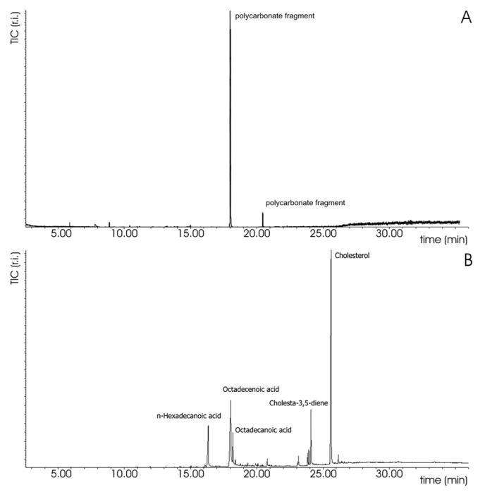
The GC–MS chromatograms of the solvent extracts obtained from the PCU spacer (Fig. 8A) exhibit the presence of signals related to carbonate segments, though in a very low amount[57].
Fig. 8.
GCeMS chromatograms of A) solution extracted from PCU spacer, B) solution extracted from PET cord.
The presence of these signals may have a double interpretation: it may be an excess of polyol coming from the synthesis or formed during molding, that is removed by the extraction procedure; or rather the hypothesized chain scission caused by in vivo degradation may be responsible for the formation of free, removable polyol. Detection of these signals in both oxidatively degraded and not egraded samples do not allow to exclude the first hypothesis.
The absence of any signal related to fatty acids and/or cholesterol derivatives indicates that the lipids absorption detected by ATR–FTIR is a minor and superficial phenomenon for the PCU spacers.
On the contrary, the GC–MS chromatogram of the extract of the PET cords (Fig. 8B) exhibits the presence of long chain aliphatic carboxylic acid at low retention time and the presence of cholesterol and its derivative species at higher retention time. This is a confirmation of the presence of organic compounds, coming from body fluids and diffused into the fibers and/or trapped into the fibers network.
3.5. Bulk evaluation of the morphology and hardness measurements
The microphase-separated morphology of PCUs depends on the fabrication and processing route as well as on the chemical formulation of the copolymer [8,37,39,58]. Differential scanning calorimetry was used to investigate the morphology and the degree of micro-phase separation of the retrieved spacers. Since the chemical degradation mainly regards the surface of the device, while the DSC measurements were performed on massive specimens, we assumed that the observed changes are mainly imputable to differences in the copolymer composition and morphology and not to biodegradation.
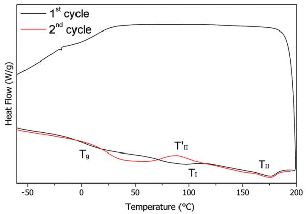
The DSC characterization of polyurethanes generally show multiple thermal transitions, whose interpretation is still under debate [58–61]. The DSC thermogram of the reference sample is shown in Fig. 9. Three thermal events are evident: a glass transition temperature (Tg) associated to the amorphous matrix and depending on the relative amount of hard and soft segments in the matrix [37,39] and two endothermic signals (TI and TII), that were attributed, respectively, to the disruption of the hard, pseudo-crystalline micro-domains and to the microphase mixing, thus to the complete dissolution of the hard domains in the matrix to create a homogenous phase [39,59].
Fig. 9.
DSC curve of the Exemplar device, exemplificative for the general thermal behavior of PCU.
No endo or exothermic signals are observed during cooling. At the second heating, the Tg value is shifted towards higher temperatures, indicating a higher content of hard segments dissolved in the soft matrix, followed by an exothermic signal (), indicating a microphase-separation [38,39,61].
The thermal transition temperatures resulting from the DSC measurements performed on the whole collection of Dynesys devices are summarized in Table 4.
Table 4.
Thermal transitions of Dynesys® devices.
| Sample |
Tg 1st cycle |
Tg 2nd cycle |
T 1 | T11 1st cycle | T11 2nd cycle |
|---|---|---|---|---|---|
| D1 | −4 | 24 | 97 | 176 | Unchanged |
| D2 | −5 | 23 | 96 | 176 | Unchanged |
| D3 | −5 | 20 | 101 | 175 | Unchanged |
| D4 | −4 | 21 | 96 | 171 | Unchanged |
| D5 | −13 | −3 | 104 | 174 | 190 |
| D6 | +1 | 26 | 100 | 177 | Unchanged |
| D8 | −3 | 23 | 101 | 168 | Unchanged |
| D9 | −12 | −6 | 103 | 178 | 195 |
| D10 | −6 | 17 | 102 | 170 | Unchanged |
| D12 | −12 | 25 | 107 | 182, 189, 198 | 179 |
| D13 | 1 | 20 | 103 | 182 | Unchanged |
| D14 | 4 | 16 | 108 | 174 | Unchanged |
| D15 | −4 | 3 | 110 | 177 | 191 |
| D19 | −4 | 21 | 105 | 171 | Unchanged |
| D20 | 1 | 28 | 106 | 170 | Unchanged |
The devices are characterized by quite heterogenous values of the glass transition temperature (Tg) at the first heating ramp (from −13 to +4 °C). As mentioned above, the Tg values depend on the relative amount of hard and soft segment in the soft matrix and the broad range of values observed in the first heating cycle might be simply attributed to different degree of microphase separation.
A particular behavior was registered for 3/14 devices (Dyn 5, Dyn 9 and Dyn 15), which also exhibited peculiar ATR–FTIR spectra. For this samples the exothermic signal T′II related to the microphase separation was detected in the cooling ramp: part of the hard segments segregate from the homogenous matrix during cooling. Accordingly, the same samples exhibit a much lower glass transition temperature at the second heating, compared with that detected for all the other devices. The remaining samples still exhibit a quite broad range of Tg (from +16 to+ 28 °C). Since the first heating ramp has the effect to cancel the thermal history of the material, materials with the same chemical composition should behave identically at a second heating ramp, independently on their previous microphase organization. Thus, the broad range of Tg values observed in the second heating cycle, after disruption of the microphase organization, suggests slight differences in the copolymers composition. In particular, larger differences must be hypothesized to explain the significantly different thermal behavior observed for the three samples mentioned above ( on cooling), confirming the ATR–FTIR observations.
All samples have variable TI (from 96 °C to 110 °C), related to the disruption of the pseudo crystalline order of the hard domains. This signal is strongly related to the thermal history of the sample[37,39,59]. All the devices were subjected to a reproducible thermal treatment: standardized postmolding annealing gives the same thermal history that should result in similar morphological behavior, creating hard domains with comparable dimension. Furthermore, all spacers had been in vivo at 37 °C for long times and all of them were stored in the same conditions after retrieval, allowing to hypothesize a homogenous thermal history. Then, the slight difference in the shape and in the temperature of this signal must be related to slight differences in the hard segment length and thus to a slight different dimensions of the microdomains.
The mixing temperatures (TII) registered in the first heating cover a range of temperature from 170 °C to 182 °C. In almost all cases the mixing temperature detected in the second ramp was unchanged, with the exception of the three cases already discussed.
1/15 sample (Dyn 12) exhibited a complex mixing signal, whose origin is still under debate.
The hardness measurements, performed with the Shore D durometer, support our hypotheses about different composition among the devices. 12/15 spacers exhibit consistent hardness values (56 ∓ 2 shore D). As expected, Dyn 5, Dyn 9 and Dyn 15 show a significantly lower hardness (45 ∓ 2 shore D). As it was confirmed by the ATR–FTIR and DSC measurements, these differences must be related to a different composition of the virgin material and not to degradation occurred in vivo.
4. Conclusions
The long term stability and the integrity of medical device polymers are very important factors in the evaluation of the performance of biomaterials. Although a number of reports on the clinical performance of the Dynesys system exists in the literature, this study represents one of the few attempts at a deeper investigation of the chemical modifications occurred during implantation.
The PET cord components were found to be minimally damaged in vivo. Residues of body fluids were found trapped in the braided fibers, but no chemical degradation was observed, confirming the known good biostability of PET, at least in the time frame studied.
The yellow color of the PCU components, compared to the colorless resin pellets, is the first sign of degradation and it likely occurred during the manufacturing process, since also the reference, never implanted sample was yellowed.
The bulk analyses performed in this study suggest a certain heterogeneity in the composition of the PCU devices. This behavior may reflect variation in manufacturing of the components. The irreversible deformation of the spacer (creep) suggests that the shape recovery is not ensured for the duration of implantation.
Various surface alterations were observed: besides those attributable to iatrogenic damage occurring during revision surgery (cuts, scratches, etc.), abrasion, microscopic surface cracks, fissures and attached micro-aggregates were the most prominent. Most of the degradation effects, aligned fissures and abraded regions, were correlated to the loading and articulation with adjacent bone. Chemical analyses showed that attached micro-aggregates were mainly organic deposition. Species containing calcium and the presence of organic species adsorbed on the surface were also observed. We postulate that the absorption of foreign species may speed up the physical degradation of the surface. In particular the adsorption of chemical agents and the presence of the attached micro-aggregates, may favor environmental stress cracking (ESC) and also amplify the effect of loading, facilitating the formation of fissures.
Some PCU spacers exhibited chemical modifications of the surface that are attributed to oxidative degradation. Although the complete degradation mechanism has not been fully elucidated yet, we have evidence that both hard and soft segments are involved. Further studies are necessary to understand the details of the degradation mechanism and, in particular, how and to what extent they can influence the in vivo performance.
Most of the observed surface changes are restricted to less than the first 10 μm, so the bulk mechanical properties of the entire device are likely not to be affected. Nevertheless, the eventual release of degradation products in the implant site, along with that of wear debris and the consequent reaction induced in the body are certainly worth more investigations.
Acknowledgments
Supported in part by NIH AR56264.
References
- [1].Lamba NMK, Woodhouse KA, Cooper SL. The chemistry of polyurethane co-polymers. In: Lamba NMK, Woodhouse KA, Cooper SL, editors. Polyurethanes in biomedical applications. Vol. 1998. CRC Press; Boca Raton, FL: pp. 5–25. [Google Scholar]
- [2].Stokes K, McVenes R, Anderson JM. Polyurethane elastomer biostability. J Biomater Appl. 1995;9(4):321–54. doi: 10.1177/088532829500900402. [DOI] [PubMed] [Google Scholar]
- [3].Thompson DG, Osborn JC, Kober EM, Schoonover JR. Effects of hydrolysis-induced molecular weight changes on the phase separation of a polyester polyurethane. Polym Degrad Stab. 2006;91(12):3360–70. [Google Scholar]
- [4].McCarthy SJ, Meijs GF, Mitchell N, Gunatillake PA, Heath G, Brandwood A, et al. In-vivo degradation of polyurethanes: transmission-FTIR microscopic characterization of polyurethanes sectioned by cryomicrotomy. Biomaterials. 1997;18(21):1387–409. doi: 10.1016/s0142-9612(97)00083-5. [DOI] [PubMed] [Google Scholar]
- [5].Wiggins MJ, MacEwan M, Anderson JM, Hiltner A. Effect of soft-segment chemistry on polyurethane biostability during in vitro fatigue loading. J Biomed Mater Res Part A. 2004;68A(4):668–83. doi: 10.1002/jbm.a.20081. [DOI] [PubMed] [Google Scholar]
- [6].Khan M, Smith N, Jones E, Finch DS, Cameron RE. Analysis and evaluation of a biomedical polycarbonate urethane tested in an in vitro study and an ovine arthroplasty model. Part I: materials selection and evaluation. Biomaterials. 2005;26(6):621–31. doi: 10.1016/j.biomaterials.2004.02.065. [DOI] [PubMed] [Google Scholar]
- [7].Yang MJ, Zhang Z, Hahn C, Laroche G, King MW, Guidoin R. Totally implantable artificial hearts and left ventricular assist devices: selecting impermeable polycarbonate urethane to manufacture ventricles. J Biomed Mater Res. 1999;48(1):13–23. doi: 10.1002/(sici)1097-4636(1999)48:1<13::aid-jbm4>3.0.co;2-4. [DOI] [PubMed] [Google Scholar]
- [8].Koberstein JT, Russell TP. Simultaneous Saxs-Dsc study of multiple endothermic behavior in polyether-based polyurethane block copolymers. Macromolecules. 1986;19(3):714e20. [Google Scholar]
- [9].Lamba NMK, Woodhouse KA, Cooper SL. Structure and physical characterization of polyurethanes. In: Lamba NMK, Woodhouse KA, Cooper SL, editors. Polyurethanes in biomedical applications. CRC Press; Boca Raton, FL: 1998. pp. 43–89. [Google Scholar]
- [10].Tanzi MC, Mantovani D, Petrini P, Guidoin R, Laroche G. Chemical stability of polyether urethanes versus polycarbonate urethanes. J Biomed Mater Res. 1997;36(4):550–9. doi: 10.1002/(sici)1097-4636(19970915)36:4<550::aid-jbm14>3.0.co;2-e. [DOI] [PubMed] [Google Scholar]
- [11].Boubakri A, Haddar N, Elleuch K, Bienvenu Y. Impact of aging conditions on mechanical properties of thermoplastic polyurethane. Mater Des. 2010;31(9):4194–201. [Google Scholar]
- [12].Xu LC, Runt J, Siedlecki CA. Dynamics of hydrated polyurethane biomaterials: surface microphase restructuring, protein activity and platelet adhesion. Acta Biomater. 2010;6(6):1938–47. doi: 10.1016/j.actbio.2009.11.031. [DOI] [PubMed] [Google Scholar]
- [13].Labow RS, Sa D, Matheson LA, Dinnes DLM, Santerre JP. The human macro-phage response during differentiation and biodegradation on polycarbonate-based polyurethanes: dependence on hard segment chemistry. Biomaterials. 2005;26(35):7357–66. doi: 10.1016/j.biomaterials.2005.05.048. [DOI] [PubMed] [Google Scholar]
- [14].Hsu SH, Kao YC, Lin ZC. Enhanced biocompatibility in biostable poly(-carbonate)urethane. Macromol Biosci. 2004;4(4):464–70. doi: 10.1002/mabi.200300082. [DOI] [PubMed] [Google Scholar]
- [15].Hsu SH, Lin ZC. Biocompatibility and biostability of a series of poly(carbonate) urethanes. Colloids Surf B. 2004;36(1):1–12. doi: 10.1016/j.colsurfb.2004.04.003. [DOI] [PubMed] [Google Scholar]
- [16].Hsu SH, Kao YC. Biocompatibility of poly(carbonate urethane)s with various degrees of nanophase separation. Macromol Biosci. 2005;5(3):246–53. doi: 10.1002/mabi.200400163. [DOI] [PubMed] [Google Scholar]
- [17].Hsu SH, Kao YC. Cell attachment and proliferation on poly(carbonate urethanes) with various degrees of nanophase separation. Macromol Biosci. 2004;4(9):891–900. doi: 10.1002/mabi.200400062. [DOI] [PubMed] [Google Scholar]
- [18].Khan M, Smith N, Jones E, Finch DS, Cameron RE. Analysis and evaluation of a biomedical polycarbonate urethane tested in an in vitro study and an ovine arthroplasty model. Part II: in vivo investigation. Biomaterials. 2005;26(6):633–43. doi: 10.1016/j.biomaterials.2004.02.064. [DOI] [PubMed] [Google Scholar]
- [19].Chandy T, Van Hee J, Nettekoven W, Johnson J. Long-term in vitro stability assessment of polycarbonate urethane micro catheters: resistance to oxidation and stress cracking. J Biomed Mater Res Part B. 2009;89B(2):314–24. doi: 10.1002/jbm.b.31218. [DOI] [PubMed] [Google Scholar]
- [20].Christenson EM, Dadsetan M, Wiggins M, Anderson JM, Hiltner A. Poly(-carbonate urethane) and poly(ether urethane) biodegradation: in vivo studies. J Biomed Mater Res Part A. 2004;69A(3):407–16. doi: 10.1002/jbm.a.30002. [DOI] [PubMed] [Google Scholar]
- [21].Zhang Z, Marois Y, Guidoin RG, Bull P, Marois M, How T, et al. Vascugraft(R) polyurethane arterial prosthesis as femoro-popliteal and femoro-peroneal bypasses in humans: pathological, structural and chemical analyses of four excised grafts. Biomaterials. 1997;18(2):113–24. doi: 10.1016/s0142-9612(96)00054-3. [DOI] [PubMed] [Google Scholar]
- [22].Christenson EM, Anderson JM, Hiltner A. Oxidative mechanisms of poly(-carbonate urethane) and poly(ether urethane) biodegradation: in vivo and in vitro correlations. J Biomed Mater Res Part A. 2004;70A(2):245–55. doi: 10.1002/jbm.a.30067. [DOI] [PubMed] [Google Scholar]
- [23].Christenson EM, Patel S, Anderson JM, Hiltner A. Enzymatic degradation of poly(ether urethane) and poly(carbonate urethane) by cholesterol esterase. Biomaterials. 2006;27(21):3920–6. doi: 10.1016/j.biomaterials.2006.03.012. [DOI] [PubMed] [Google Scholar]
- [24].Tang YW, Labow RS, Santerre JP. Enzyme-induced biodegradation of polycarbonate-polyurethanes: dependence on hard-segment chemistry. J Biomed Mater Res. 2001;57(4):597–611. doi: 10.1002/1097-4636(20011215)57:4<597::aid-jbm1207>3.0.co;2-t. [DOI] [PubMed] [Google Scholar]
- [25].Tang YW, Labow RS, Santerre JP. Enzyme-induced biodegradation of poly-carbonate polyurethanes: dependence on hard-segment concentration. J Biomed Mater Res. 2001;56(4):516–28. doi: 10.1002/1097-4636(20010915)56:4<516::aid-jbm1123>3.0.co;2-b. [DOI] [PubMed] [Google Scholar]
- [26].Tang YW, Labow RS, Santerre JP. Isolation of methylene dianiline and aqueous-soluble biodegradation products from polycarbonate-polyurethanes. Biomaterials. 2003;24(17):2805–19. doi: 10.1016/s0142-9612(03)00081-4. [DOI] [PubMed] [Google Scholar]
- [27].Anderson PA, Rouleau JP, Toth JM, Riew KD. A comparison of simulator-tested and -retrieved cervical disc prostheses. J Neurosurg Spine. 2004;1(2):202–10. doi: 10.3171/spi.2004.1.2.0202. [DOI] [PubMed] [Google Scholar]
- [28].Elsner JJ, Mezape Y, Hakshur K, Shemesh M, Linder-Ganz E, Shterling A, et al. Wear rate evaluation of a novel polycarbonate-urethane cushion form bearing for artificial hip joints. Acta Biomater. 2010;6(12):4698–707. doi: 10.1016/j.actbio.2010.07.011. [DOI] [PubMed] [Google Scholar]
- [29].Zimmer Inc Dynesys® dynamic stabilization system. 2012 Oct; http://www.zimmer.com/z/ctl/op/global/action/1/id/9165/template/IN; 2007.
- [30].Grob D, Benini A, Junge A, Mannion AF. Clinical experience with the Dynesys semirigid fixation system for the lumbar spine – surgical and patient-oriented outcome in 50 cases after an average of 2 years. Spine. 2005;30(3):324–31. doi: 10.1097/01.brs.0000152584.46266.25. [DOI] [PubMed] [Google Scholar]
- [31].Muller RJ, Kleeberg I, Deckwer WD. Biodegradation of polyesters containing aromatic constituents. J Biotechnol. 2001;86(2):87–95. doi: 10.1016/s0168-1656(00)00407-7. [DOI] [PubMed] [Google Scholar]
- [32].Yarwood J, Sammon C, Everall N. An FT-IR study of the effect of hydrolytic degradation on the structure of thin PET films. Polym Degrad Stab. 2000;67(1):149–58. [Google Scholar]
- [33].Zadhoush A, Hosseini SS, Taheri S, Mehrabani-Zeinabad A. Hydrolytic degradation of poly(ethylene terephthalate) J Appl Polym Sci. 2007;103(4):2304–9. [Google Scholar]
- [34].Shen M, Zhang K, Koettig P, Welch WC, Dawson JM. In vivo biostability of polymeric spine implants: retrieval analyses from a United States investiga tional device exemption study. Eur Spine J. 2011;20(11):1837–49. doi: 10.1007/s00586-011-1812-8. [DOI] [PMC free article] [PubMed] [Google Scholar]
- [35].Ianuzzi A, Kurtz SM, Kane W, Shah P, Siskey R, van Ooij A, et al. In vivo deformation, surface damage, and biostability of retrieved Dynesys systems. Spine. 2010;35(23):E1310–6. doi: 10.1097/BRS.0b013e3181d6f84f. [DOI] [PubMed] [Google Scholar]
- [36]. http://www.dsm.com/en_US/medical/public/home/downloads/publications/PP_Orthopedic_implant_materials_of_DSM_Biomedical.pdf.
- [37].Leung LM, Koberstein JT. Dsc annealing study of microphase separation and multiple endothermic behavior in polyether-based polyurethane block co-polymers. Macromolecules. 1986;19(3):706–13. [Google Scholar]
- [38].Saiani A, Daunch WA, Verbeke H, Leenslag JW, Higgins JS. Origin of multiple melting endotherms in a high hard block content polyurethane. 1. Thermo-dynamic investigation. Macromolecules. 2001;34(26):9059–68. [Google Scholar]
- [39].Cipriani E, Zanetti M, Brunella V, Costa L, Bracco P. Thermoplastic polyurethanes with polycarbonate soft phase: effect of thermal treatment on phase morphology. Polym Degrad Stab. 2012;97(9):1794–800. [Google Scholar]
- [40].Hughes-Dillon K, Schroeder LW. Stress cracking of polyurethanes by absorbed steroids. Polym Degrad Stab. 1998;60(1):11–20. [Google Scholar]
- [41].Martin DJ, Warren LAP, Gunatillake PA, McCarthy SJ, Meijs GF, Schindhelm K. New methods for the assessment of in vitro and in vivo stress cracking in biomedical polyurethanes. Biomaterials. 2001;22(9):973–8. doi: 10.1016/s0142-9612(00)00262-3. [DOI] [PubMed] [Google Scholar]
- [42].Bernacca GM, Mackay TG, Wilkinson R, Wheatley DJ. Calcification and fatigue failure in a polyurethane heart-valve. Biomaterials. 1995;16(4):279–85. doi: 10.1016/0142-9612(95)93255-c. [DOI] [PubMed] [Google Scholar]
- [43].Pongkitwitoon S, Hernandez R, Weksler J, Padsalgikar A, Choi T, Runt J. Temperature dependent microphase mixing of model polyurethanes with different intersegment compatibilities. Polymer. 2009;50(26):6305–11. [Google Scholar]
- [44].Spirkova M, Pavlicevic J, Strachota A, Poreba R, Bera O, Kapralkova L, et al. Novel polycarbonate-based polyurethane elastomers: composition-property relationship. Eur Polym J. 2011;47(5):959–72. [Google Scholar]
- [45].Miller JA, Lin SB, Hwang KKS, Wu KS, Gibson PE, Cooper SL. Properties of polyether polyurethane block copolymers e effects of hard segment length distribution. Macromolecules. 1985;18(1):32–44. [Google Scholar]
- [46].Lee HS, Wang YK, Hsu SL. Spectroscopic analysis of phase-separation behavior of model polyurethanes. Macromolecules. 1987;20(9):2089–95. [Google Scholar]
- [47].Qi HJ, Boyce MC. Stress-strain behavior of thermoplastic polyurethanes. Mech Mater. 2005;37(8):817–39. [Google Scholar]
- [48].Costa L, Bracco P, del Prever EB, Luda MP, Trossarelli L. Analysis of products diffused into UHMWPE prosthetic components in vivo. Biomaterials. 2001;22(4):307–15. doi: 10.1016/s0142-9612(00)00182-4. [DOI] [PubMed] [Google Scholar]
- [49].Fare S, Petrini P, Motta A, Cigada A, Tanzi MC. Synergistic effects of oxidative environments and mechanical stress on in vitro stability of polyetherur-ethanes and polycarbonateurethanes. J Biomed Mater Res. 1999;45(1):62–74. doi: 10.1002/(sici)1097-4636(199904)45:1<62::aid-jbm9>3.0.co;2-f. [DOI] [PubMed] [Google Scholar]
- [50].Servay T, Voelkel R, Schmiedberger H, Lehmann S. Thermal oxidation of the methylene diphenylene unit in MDI-TPU. Polymer. 2000;41(14):5247–56. [Google Scholar]
- [51].Wrobleski DA, Langlois DA, Bruce Orler E, Labouriau A, Uribe M, Houlton R, et al. Accelerated aging and characterization of a plasticized poly(ester urethane) binder. In: Celina MC, Wiggins JS, Billingham NC, editors. Polymer degradation and performance. American Chemical Society; Washinton, DC: 2009. pp. 181–96. [Google Scholar]
- [52].Hoyle CE, Shah H, Moussa K. Photolysis of methylene 4,4′-diphenyldiisocya-nate-based polyurethane ureas and polyureas. In: Clough RL, Billingham NC, Gillen KT, editors. Polymer durability. American Chemical Society; Washinton, DC: 1996. pp. 91–111. [Google Scholar]
- [53].Giroux TA, Cooper SL. FTIR/ATR studies of protein adsorption on plasma derivatized polyurethanes. J Colloid Interface Sci. 1991;146(1):179–94. [Google Scholar]
- [54].Zhang Z, King MW, How TV, Laroche G, Guidoin R. Chemical and morphological analysis of explanted polyurethane vascular prostheses: the challenge of removing fixed adhering tissue. Biomaterials. 1996;17(19):1843–8. doi: 10.1016/0142-9612(95)00246-4. [DOI] [PubMed] [Google Scholar]
- [55].Donelli I, Freddi G, Nierstrasz VA, Taddei P. Surface structure and properties of poly-(ethylene terephthalate) hydrolyzed by alkali and cutinase. Polym Degrad Stab. 2010;95(9):1542–50. [Google Scholar]
- [56].Lin-Vien D, Colthup NB, Fateley WG, Grasselli JG. The handbook of infrared and Raman characteristic frequencies of organic molecules. Accademic Press, Inc.; San Diego, CA: 1991. [Google Scholar]
- [57].Moldoveanu SC. Poly(carbonates) and poly(anhydrides) In: Moldoveanu SC, editor. Analytical pyrolysis of synthetic organic polymers. Elsevier; Winston-Salem, NC: 2005. pp. 557–71. [Google Scholar]
- [58].Martin DJ, Meijs GF, Renwick GM, McCarthy SJ, Gunatillake PA. The effect of average soft segment length on morphology and properties of a series of polyurethane elastomers .1. Characterization of the series. J Appl Polym Sci. 1996;62(9):1377–86. [Google Scholar]
- [59].Martin DJ, Meijs GF, Gunatillake PA, McCarthy SJ, Renwick GM. The effect of average soft segment length on morphology and properties of a series of polyurethane elastomers .2. SAXS-DSC annealing study. J Appl Polym Sci. 1997;64(4):803–17. [Google Scholar]
- [60].Chen TK, Chui JY, Shieh TS. Glass transition behaviors of a polyurethane hard segment based on 4,4′-diisocyanatodiphenylmethane and 1,4-butanediol and the calculation of microdomain composition. Macromolecules. 1997;30(17):5068–74. [Google Scholar]
- [61].Hernandez R, Weksler J, Padsalgikar A, Choi T, Angelo E, Lin JS, et al. A comparison of phase organization of model segmented polyurethanes with different intersegment compatibilities. Macromolecules. 2008;41(24):9767–76. [Google Scholar]


