Abstract
Background
Accurate needle placement is the first concern in percutaneous MRI-guided prostate interventions. In this phantom study, different sources contributing to the overall needle placement error of a MRI-guided robot for prostate biopsy have been identified, quantified, and minimized to the possible extent.
Methods and Materials
The overall needle placement error of the system was evaluated in a prostate phantom. This error was broken into two parts: the error associated with the robotic system (called before-insertion error) and the error associated with needle-tissue interaction (called due-to-insertion error). The before-insertion error was measured directly in a soft phantom and different sources contributing into this part were identified and quantified. A calibration methodology was developed to minimize the 4-DOF manipulator’s error. The due-to-insertion error was indirectly approximated by comparing the overall error and the before-insertion error. The effect of sterilization on the manipulator’s accuracy and repeatability was also studied.
Results
The average overall system error in phantom study was 2.5 mm (STD=1.1mm). The average robotic system error in super soft phantom was 1.3 mm (STD=0.7 mm). Assuming orthogonal error components, the needle-tissue interaction error was approximated to be 2.13 mm thus having larger contribution to the overall error. The average susceptibility artifact shift was 0.2 mm. The manipulator’s targeting accuracy was 0.71 mm (STD=0.21mm) after robot calibration. The robot’s repeatability was 0.13 mm. Sterilization had no noticeable influence on the robot’s accuracy and repeatability.
Conclusions
The experimental methodology presented in this paper may help researchers to identify, quantify, and minimize different sources contributing into the overall needle placement error of an MRI-guided robotic system for prostate needle placement. In the robotic system analyzed here, the overall error of the studied system remained within the acceptable range.
Keywords: MRI-compatible robot, prostate biopsy, accuracy assessment, phantom study, transperineal access
Introduction
Prostate cancer is the most common cancer in men in the United States [1]. The definitive diagnostic method for this disease is core needle biopsy. According to the statistics, each year approximately 1.5 million prostate biopsy procedures are performed only in the United States [2]. Transrectal ultrasound (TRUS) guidance is the “Gold Standard” navigation method for biopsy due to its real-time nature, relative low cost, and ease of use. However, this imaging modality is not capable of visualizing cancer but rather the contour of prostate, resulting in a significant number of false-negatives in conventional TRUS-guided systematic biopsy [3], where 6–12 cores equally distributed within the prostate are sampled.
Magnetic Resonance Imaging (MRI) has the potential to improve prostate biopsy due to its high sensitivity for detecting prostate tumors, excellent soft tissue contrast, high spatial resolution, and multi-planar volumetric imaging capabilities [4]. Manual transperineal prostate biopsy has been reported in [5, 6]. Due to limited accuracy, needle placement with template grid was proposed in [7]. Unfortunately, the template does not allow for arbitrary needle trajectory. Robotic systems can assist in solving this issue. Several MRI-compatible robots have been reported for prostate interventions. They used transrectal, transperineal or transgluteal access to the prostate. MRI-guided transperineal prostate interventions were studied in patient experiments inside open MRI scanner by Chinzei [8]. In [9], Di Maio designed systems to assist transperineal intra-prostatic needle placement. In [10] Tadakuma developed an MRI-compatible robot for transperineal needle placement using dielectric elastomer actuators (DEAs). In [11] Stoianovici developed a pneumatically actuated device for transperineal brachytherapy seed placement. In [12] Fischer developed a pneumatic 2-DOF robot for transperineal prostate needle placement. In [13] Goldenberg developed a robotic system employing ultrasonic actuators for MRI-guided transperineal prostate intervention. In [14] van den Bosch reported a hydraulically and pneumatically actuated tapping device to alleviate undesirable prostate displacement and deformation. Su reported a 3-DOF Cartesian robot for MRI-guided transperineal needle alignment with a 3-DOF needle steering module for teleoperated and autonomous seed implantation [15, 16].
The required needle placement accuracy in prostate biopsy is determined by the clinically significant size of prostate cancer foci. There is no general agreement on this value. In [17] 0.5 mL tumor volume was proposed as the limit for the significant prostate cancer foci. A 0.5 mL spherical shaped tumor has radius of almost 5 mm which means the needle placement accuracy should be better than 5 mm. In this work we consider 3 mm as the accuracy limit since we are conducting phantom studies.
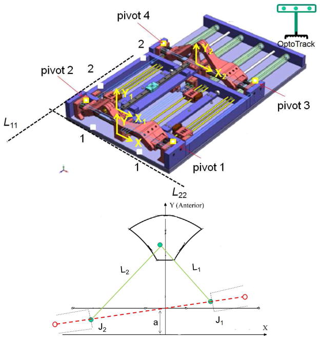
To ensure the overall error in needle placement remains below the required threshold, systematic accuracy assessment is necessary in order to identify and quantify all error components. Prior accuracy assessment studies focused only on manual MRI-guided transperineal prostate biopsy with use of the template grid [18, 19]. In this study however, we provide a systematic accuracy assessment method for robotic MRI-guided prostate biopsy. In addition, a calibration methodology is proposed and implemented based on the manipulator’s kinematics in order to minimize the error caused by this key element of the whole system. Figure 1 shows a prototype of the specific manipulators studied in this paper. The system is a MRI-guided prostate intervention robot for transperineal needle placement with pneumatic actuation which provides 5-Degree of Freedom (DOF) needle positioning in MRI coordinates [20–22]. Although the calibration process proposed here is specific to this robot, our approach (discussed in section 3.4) can be applied to manipulators of different kinematics.
Fig. 1.
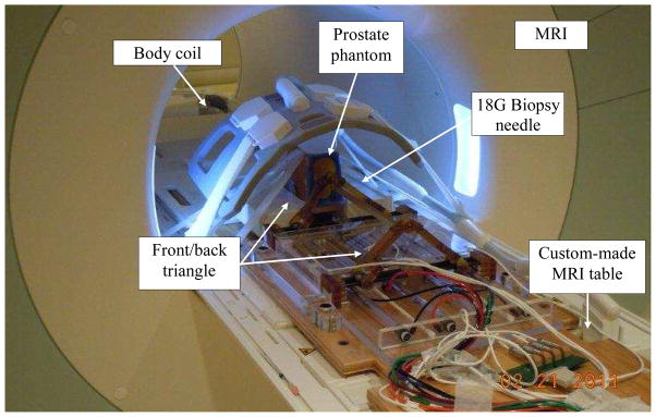
The 4-DOF pneumatic robot for MRI-guided transperineal prostate biopsy used in this study.
Error sources and components
Classification of error sources
We define the needle placement error in robotic prostate biopsy as the distance between the center of the needle artifact and the predefined target position both measured in MRI image. This error has two main components: intrinsic and extrinsic errors. Intrinsic error comprises: 1) error associated with the robotic system which occurs before needle insertion, 2) error caused by needle-tissue interaction i.e. needle deflection, and prostate motion and deformation which occurs as the result of needle insertion. Extrinsic error is caused by patient motion, bladder filling, external surgical tool caused tissue deformation such as endorectal imaging coil probe, etc. Table 1 categorizes different sources of needle placement error with the corresponding components and the way each part can be minimized.
Table 1.
Different sources of error in robot assisted prostate needle placement under MRI guidance
| Error Source | Different parts | Minimization solution | |
|---|---|---|---|
| Intrinsic | 1. Robotic system |
|
|
| 2. Needle-tissue interaction |
|
||
| Extrinsic | 1. Patient motion | - | |
| 2. Probe caused deformation | - |
|
|
| 3. Bladder filling | - | - |
FEA: Finite Element Analysis
In our phantom study, extrinsic errors were ignored. In fact, the focus of this study is placed on intrinsic errors, particularly the error associated with the robotic system. The other intrinsic error component, i.e. the error caused by needle-tissue interaction was indirectly approximated as well.
Identification of robotic system error components
To indentify robotic system error components, the targeting workflow are reviewed (Fig. 2): first, the target and needle trajectory are specified by clinician in the 3D Slicer (www.slicer.org) based navigation software. Both the target and the needle trajectories are expressed in RAS (Right-Left, Anterior-Posterior, Superior-Inferior) scanner coordinate system (Right-Left, Anterior-Posterior, and Superior-Inferior see Fig. 2), thus they should be converted to the robot coordinate system (XYZ). For this reason, a fiducial frame called Z-frame is used [29]. The origin and the rotation matrix representing the three orthogonal vectors of the Z-frame are sent by the navigation software to the robot controller along with the target position and needle trajectory. Then, the target position and corresponding needle trajectory in XYZ are found as follows:
| (1) |
where [x, y, z] and [u, v, w] are target position and needle trajectory, respectively. and are transformations from the RAS to Z-frame and from Z-frame to robot coordinates, respectively. When the target position and needle trajectory are specified in the robot coordinate system, the robot controller solves the inverse kinematic problem in order to reach that target position and sends the command to each actuator. Then, the robot moves to align the needle with the target. Next, the needle is inserted manually for the calculated depth. Finally, confirmation images are taken. The distance between the needle susceptibility artifact and pre-planned target is computed as the targeting error.
Fig. 2.
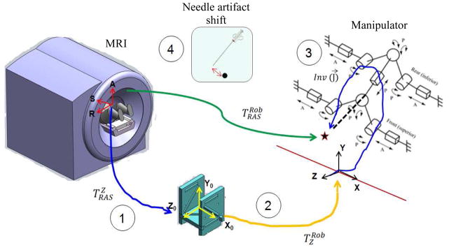
Different sources of the error contributing to the MRI-guided robotic system: Z-frame registration error, robot to Z-frame registration error, the manipulator’s error, and the artifact shift.
Based on the targeting workflow, four possible sources of error were identified in association with the robotic system: 1) RAS to Z-frame transformation error referred to as Z-frame registration error, 2) Z-frame to robot (XYZ) transformation error, 3) manipulator’s needle positioning error, and 4) and positional error due to susceptibility artifact shift. In the following sections, we propose quantification and reduction methods for each of them.
Methods and materials
In this section, we propose methods for measurement of each component of the robotic system error. For the error caused by the manipulator, a calibration method is proposed in order to be able to compensate for this error. Then, the total error of the robotic system (i.e. the overall error before insertion) and the overall error are separately quantified.
Z-frame registration accuracy evaluation
The Z-frame is used to register the scanner (RAS) and robot coordinate systems (Fig. 2). The idea of using Z-frame was proposed in [29]. The Z-frame has seven rigid tubes with 7.5 mm inner diameters filled with a contrast agent (MR Spots, Beekley, Bristol, CT) placed on three adjacent faces of a 60 mm cube, thus forming a Z-shape in the images. The seven tubes are automatically detected on cross-sectional MRI images of the Z-frame in 3D Slicer, providing the location and orientation of the Z-frame in the MRI coordinate system. Since the Z-frame is attached in a predefined position relative to the robot on the custom-made MRI table, the position of the target can be transformed from image coordinates to robot coordinates. This registration procedure can be imprecise. For this reason, a calibration methodology was proposed and evaluated in [19]. Summary of the method is as follows: registration error is usually provided as Target Registration Error (TRE). TRE could be defined as follows [30]:
| (2) |
where N is the number of targets, qi is actual measurement of targets in MRI coordinate, F is the calibration transformation (rotation and translation matrices) found after Z-frame registration, and pi is the desired position we are going to reach in phantom coordinate system. A geometric phantom of 40 targets (pi) within the typical position of an average prostate gland was placed in a tank of water and then imaged (qi). The transformation matrix (4×4) was found in parallel by imaging the Z-frame (i.e. F (.)). Then, these targets were uploaded in 3D Slicer and were tried to be reached. In order to eliminate any other errors and focus on the registration error only, the robot was replaced by a “simulator”. Then, simulator computes F (pi) based on the robot inverse kinematics and marked it as a virtual point in 3D Slicer. These transformed points (F(pi)) were then compared to the actual measurement in MRI image (qi) according to equation (2) and the TRE was reported.
Z-frame to robot registration accuracy evaluation
By design, Z-frame and robot coordinate are aligned and should be a pure translation. This source has a small contribution to the overall system inaccuracy since this translation does not involve kinematic parameters unlike other sources. This error can be negligible if the manufacturing accuracy is adequate (i.e. < 0.1 mm accuracy). Physical measurement showed that this error is negligible in our robotic system. To eliminate this error source permanently, the Z-frame should be rigidly attached to the robot [16, 23].
Needle artifact shift evaluation
The surgical needle is not directly visible in MRI. Instead, it leaves a dark void on the image referred to as susceptibility needle artifact which is caused by signal loss in the vicinity of the needle. The size, shape and location of the artifact depend on imaging parameters, needle material and shape, needle orientation relative to the static field B0, and frequency encoding direction [31]. Assuming that the center of mass of the artifact represents the axis of the needle, the artifact shape and size of the artifact become less important. The problem is how to relate the location of the needle artifact (the central axis of the void) and the true position of the needle. A few studies have been reported on this topic as reviewed in [31] and [18]. Unfortunately, the results of those studies are not applicable to the problem we are studying since the needle orientation and imaging parameters are different. We decided to follow the approach described in [31]. We selected different target positions within prostate capsule. For each target, we consecutively inserted two needles, a 1.5 mm glass needle as the ground truth and an 18G biopsy needle, into a custom-made soft phantom. The imaging parameters during needle insertions were as follows: 2D Turbo Spin Echo (TSE) sequence (TR/TE = 3000/103 ms; acquisition matrix = 320 × 205; flip angle 140 deg; field of view = 192 × 240; thickness = 2 mm; receiver bandwidth= 252 Hz/pixel). The artifact caused by the glass needle was significantly smaller than the void caused by the biopsy needle. The in-plane distance between the central axes of the two artifacts was defined as the susceptibility needle artifact shift. The error normal to the plane is ignored (see section 3.6).
The manipulator’s accuracy
In this section, the robot is first calibrated in order to compensate for manufacturing errors. Then, the robot accuracy is quantified using optical tracking system.
a) Calibration of the manipulator
The manipulator’s kinematic parameters can differ from designed values due to manufacturing inaccuracies. Since the robot is mainly made of plastic for the sake of MRI-compatibility, this issue can be more significant. To minimize this important source of error, a calibration method is proposed. We approach this problem by considering the robot inverse kinematics as follows: the robot comprises a pair of planar 2-DOF mechanisms coupled to each other by an adjustable linkage and two spherical joints at both ends (Fig. 3-a). After the target and the needle trajectory are transformed into the robot coordinates, the line defined by the target position and the needle trajectory are intersected by the front and back triangle planes, as depicted in Fig. 3-a, yielding (x1, y1) and (x2, y2). Then, the front and back 2-DOF planar mechanisms (Fig. 3-a) are kinematically structured by using prismatic actuators in order to achieve the following displacements:
| (3) |
where J1 and J2 are the displacements of the actuators. A similar relationship exists for J3 and J4 (back triangle mechanisms) with replacing x2 and y2 for x1 and y1. As seen in equation (3), two sets of parameters are involved in the needle tip position: (x, y) which we call them kinematic parameters, and (L, a) which we call them geometric parameters. Due to manufacturing errors, the front and back triangle planes might be displaced and disoriented arbitrarily thus impacting (x, y). Also, due to these inaccuracies, geometric parameters might be different from desired values. In the following sections, we will propose methods for compensating for these errors.
Fig. 3.
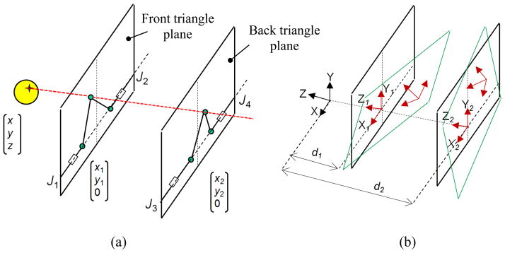
Robot inverse kinematics: (a) front and back triangle coordinate systems can be translated and rotated arbitrarily (b) due to manufacturing inaccuracy
A) Modification of kinematic parameters
Three local coordinate systems can be defined as depicted in Fig. 3-b: XYZ, the robot coordinate system, X1Y1Z1 the front triangle coordinate system and X2Y2Z2 the back triangle coordinate system. Ideally, X1Y1Z1 and X2Y2Z2 are perfectly aligned with XYZ and their origins are (0, 0, -d1) and (0, 0, -d2), respectively in XYZ coordinates, where d1 and d2 are constant values. However, we need post- fabrication measurements and updating these values. Theoretically, in the X1Y1Z1 and X2Y2Z2, origin displacement and rotation could take place in all three directions (Fig. 3-b). Physically, the rotation is constrained to the Y axis and the shift of origin is constrained in the X and Z directions since the front and rear triangles are sitting on the same plane i.e. robot base plane. In order to compensate for this disorientation and displacement, two transformation matrices are defined as follows: T1= [R1, TR1; 0 0 0 1]T and T2= [R2, TR2; 0 0 0 1]T where T1 and T2 are transformations from XYZ to X1Y1Z1 and X2Y2Z2, respectively. Ideally, Ri is identity and TRi= [0, 0, -di] where i= {1, 2}. These transformation matrices should be pre-multiplied by the target and needle trajectory vectors before they are used in the robot inverse kinematics in order to compensate for errors.
In order to quantify R1 and R2, we need to find the true XYZ, X1Y1Z1 and X2Y2Z2 for the robot. For this purpose, we used an optical tracking system and collected data as depicted in Fig. 4-a. X is defined by two sufficiently distant points on the front side of the robot base plate (point 1). X1 is defined by pivots 1 and 2 which are precisely drilled holes along the actuator’s 1 and 2 axes. Likewise, X2 is defined by pivots 3 and 4. Three out of the four pivot points define a plane whose normal defines the Y, Y1 and Y2 direction respectively. Y, Y1 and Y2 are parallel since the front and back triangles rest on the same plane (robot base plate). Z, Z1 and Z2 are found by cross production of the X and Y unit vectors.
Fig. 4.
(a) Data point collection for measuring true T1 and T2 and for (b) true geometric parameter
The translation in X direction is found by comparing the distance between the midpoints of the pivot points and line L11 and the corresponding design values. The translation in Y direction is found by comparing the distance between the midpoints of the pivot points and line L22 and the corresponding design values.
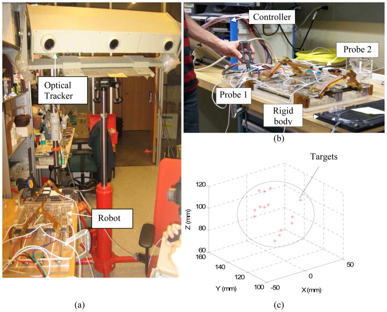
The experimental setup is shown in Fig. 5-a. It comprised of the robot, robot controller, an optical tracking device (Optotrak 3020 NDI, Waterloo, Canada) and two 6-DOF tracking probes (Fig. 5-b), one for point data collection and one for needle tip measurement. According to the catalog of the device, the RMS accuracy at 2.5 m distance is 0.1 mm in x and y direction and 0.15 mm in z direction. Reproducibility was 0.11 mm in our study based on the pivot calibration that we conducted in the beginning of the experiment. However, it should be noted that Optotrak’s accuracy may vary depending upon the distance between the camera and the measuring point. For this reason, we put the robot at a distance recommended by the company relative to the optical tracking system. At this distance, the accuracy is optimal and supposedly, as claimed by the producer. We also used a rigid dynamic reference body clamped next to the robot (dark plate clamped next to the robot as indicated in Fig. 5-b) in order to eliminate the effect of unwanted movement in the head of the Optotrak.
Fig. 5.
(a) The experimental setup, (b) robot calibration and accuracy analysis with two tracking probes, number 1 for calibration and number 2 for needle tip measurement, (c) target positions and approximate prostate boundary in XYZ
The necessary reference data points were collected as explained before and depicted in Fig. 4-a. For each point, average of 200 data points (STD < 0.1 mm) was collected to ensure consistency.
T1 and T2 were computed as discussed and are provided below:
| (4) |
Although the rotation part was close to identity, it could compensate for up to 4 mm error on the backplane as the backplane is located 320 mm apart from the target. The translation shifts in the X and Z directions were below 2 mm, considering that d1= −18.5 mm and d2= 300.5 mm.
B) Geometric parameter updates
These parameters include L1, L2, a1, and L3, L4, and a2 as shown in Fig. 4- (b). In order to find L1 and L2, J1 and J2 are set at designated positions. The end-effector position is measured by an optical tracking system as shown in Fig. 5-a. Having these three points, L1 and L2 were found. L3 and L4 were found in the same way while the constant a1 and a2 were directly measured. The updated geometric parameters are shown in Table 2. The measured parameters closely matched the designed parameters.
Table 2.
Geometric parameter calibration (mm)
| L1 | L2 | L3 | L4 | a1 | a2 | |
|---|---|---|---|---|---|---|
| Measured | 119.0 | 119.4 | 120.0 | 120.1 | 30.8 | 30.0 |
| Designed | 120.0 | 120.0 | 120.0 | 120.0 | 30.0 | 30.0 |
C) Inverse and forward kinematics modification
The kinematic parameters as well as geometric parameters are updated as the result of manufacturing errors. Hence, the robot inverse and forward kinematics are modified as shown in equations (4–6). The forward kinematics is used to ascertain the correctness of the inverse kinematic solution before commands are sent to the robot joints.
Updated inverse kinematics
| (5) |
Updated forward kinematics
| (6) |
where , and ξ3 = J1 − J2,
| (7) |
where , and ζ3 = J3 − J4,
Having (x1, y1) and (x2, y2) and needle depth d, the target P and the needle trajectory vector l are obtained as follows:
| (8) |
, and
| (9) |
b) Manipulator’s accuracy assessment
Robot accuracy is evaluated in two different space domains: joint space (i.e. J1, J2, J3, and J4) and robot space (i.e. needle tip in XYZ) in order to separate inaccuracy of actuator and other sources (e.g. encoder reading error, joint tolerance, etc.) which cannot be systematically fixed. The experimental procedure was as follows: an optical tracking probe was placed into the front needle guide as indicated in Fig. 5-b in order to obtain the needle tip position. Data was recorded relative to the rigid dynamic reference body clamped next to the robot. First, the robot was registered to the optical tracking coordinates by collecting 4 pivot points as shown in Fig. 4-a. Then, 14 target positions were chosen within the robot’s workspace (Fig. 5-c). The robot was commanded to those targets. Each time, all 4 encoder readings were recorded for joint space accuracy evaluation and the needle tip was recorded by the optical tracking probe for needle placement accuracy evaluation. Both probes were pivot-calibrated prior to measurement. Joint space error was defined as the difference between the sent command and the actual reading. Robot targeting accuracy was defined as the distance between the desired points calculated based on the updated forward kinematics and the corresponding points measured with optical tracking system.
Total error of the robotic system
The total error caused by the robotic system (including all four sub-sources as listed in Table 1) was measured in a separate experiment as depicted in Fig. 6. A phantom was made by removing the premium mimicking rubber layer and replacing the inside gel of a commercial prostate intervention training phantom (CIRS 053, Computerized Imaging Reference Systems, Inc., Norfolk, VA) with Super Soft Plastic (M–F Manufacturing, Inc., Ft. Worth, TX, USA). The liquid softener and liquid plastic were mixed at a ratio of 4 to 1 in order to eliminate the error caused by needle-tissue interaction.
Fig. 6.
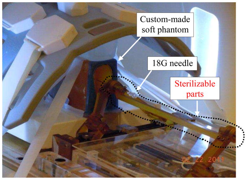
Needle placement in a soft phantom for robotic system total error and artifact shift measurement. CIRS 053 prostate phantom was customized to eliminate needle deflection.
The phantom and the Z-frame were secured on the custom-made MRI table. The image of the Z-frame was acquired using 3D Fast Low Angle Shot (FLASH) (TR/TE: 12 ms/1.97 ms; acquisition matrix: 256 × 256; flip angle 45°; field of view: 160 × 160 mm; slice thickness: 2 mm; receiver bandwidth: 400 Hz/pixel; number of averages 3). Next, the image was uploaded in 3D Slicer and the transformation matrix from RAS to robot coordinate (XYZ) was calculated by the software. The prostate phantom was then imaged and the DICOM images were imported to the navigation software. The images of the phantom were acquired using 2D Turbo Spin Echo (TSE) sequence (TR/TE = 5250/100 ms; acquisition matrix = 320 × 224; flip angle = 150°; field of view = 140 × 140 mm; slice thickness = 3 mm; receiver bandwidth= 203 Hz/pixel). Then, the Z-frame was removed and the robot was placed in a pre-defined pose on MRI board. In 3D Slicer, 9 target locations were randomly selected within the prostate region. These targets were chosen in different areas of the prostate capsule to ensure that the reported average error is independent of the target location. The software sent those targets and needle trajectories to the robot controller along with the RAS-to-XYZ transformation matrix (calculated by Z-frame registration). After each glass needle insertion, a confirmation image was acquired around the target with 2D Turbo Spin Echo (TSE) sequence (TR/TE = 3000/103 ms; acquisition matrix = 320 × 205; flip angle 140 deg; field of view = 192 × 240; thickness = 2 mm; receiver bandwidth= 252 Hz/pixel) in the axial plane in order to measure the 2D needle placement error. The 2D needle placement error was defined as the distance between the predefined target and the center of the needle artifact on the same axial plane, as obtained.
Overall needle placement error
The overall needle placement error was evaluated in the same way as explained in previous section but instead with the use of a multi-modality commercial prostate intervention training phantom (CIRS 053) in its original shape. The prostate phantom was imaged and the images were imported into the navigation software. A total of 15 targets were randomly selected in the prostate capsule. After inserting a 18-gauge×20cm needle with bevel-shaped tip (MRI Bio Gun, E-Z-EM, Westbury, NY) at each target, a confirmation image was taken. The 2D needle placement error was defined as the distance between the center of the needle artifact on the same axial plane and the predefined target. The error in S direction (normal to the axial image plane) was ignored as the needle artifact was visible in a slide before and after the predefined target. Also, the biopsy sample is typically 15–20 mm long implying that few millimeters of error in needle insertion depth is practically insignificant from the perspective of cancer yield.
Results
Error components of the robotic system
Z-frame registration error measurement
The robot-to-image registration error defined as TRE was 1.8 mm for the inner area of the prostate capsule [19].
Z-frame to robot calibration error measurement
This error was negligible as discussed in section 4.2.
Susceptibility artifact shift measurement
Table 3 shows the results. ErR and ErA are error in R and A direction, respectively. ErTot is the total error. The results show that the artifact shift is approximately 0.2 mm in average (i.e. 1.29 −1.09=0.2 mm).
Table 3.
Needle artifact shift study results
| Targets | Glass needle
|
Titanium needle
|
||||
|---|---|---|---|---|---|---|
| ErR | ErA | ErTot | ErR | ErA | ErTot | |
|
|
|
|||||
| #1 | −0.10 | −1.33 | 1.33 | 0.30 | −0.13 | 0.32 |
| #2 | −0.74 | 0.20 | 0.76 | −0.24 | 0.50 | 0.55 |
| #4 | −2.50 | −1.50 | 2.91 | −1.80 | −1.40 | 2.28 |
| #5 | −0.70 | −0.30 | 0.76 | 0.20 | −0.30 | 0.36 |
| #6 | 1.16 | 0.90 | 1.46 | 1.76 | 1.50 | 2.36 |
| #7 | −0.06 | −0.85 | 0.85 | −0.40 | −0.35 | 0.53 |
| #8 | −0.40 | 1.40 | 1.40 | −0.10 | 1.20 | 1.20 |
| #9 | −1.30 | 0.60 | 1.43 | −1.30 | 0.00 | 1.30 |
| Avg | −0.46 | −0.14 | 1.29 | −0.08 | 0.09 | 1.09 |
| STD | 1.05 | 1.00 | 0.70 | 1.07 | 0.87 | 0.76 |
Manipulator’s error measurement
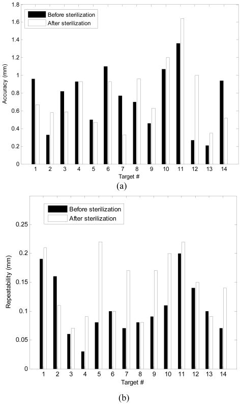
As shown in Table 4, the average of joint space error was 0.2 mm (STD =0.22 mm).The average needle positioning accuracy was 0.74 mm (STD =0.33 mm), shown in Fig. 7-a. For each target shown in Fig. 7-a, the error was defined as the average absolute distance between the measured needle tip (i.e. the probe tip) and the target calculated from the forward kinematics. Repeatability was defined as the standard deviation of the error over 10 repetitions for reaching each target (Fig. 7-b). The mean value of the robot repeatability was 0.13 mm. Although the accuracy of the optical tracking system used for the manipulator’s accuracy evaluation was not better than 0.15 mm, we think that this accuracy is still adequate for this study since the error of the manipulator is almost 5 times larger (0.74 mm).
Table 4.
Joint space accuracy (mm)
| Axis 1 | Axis 2 | Axis 3 | Axis 4 | Avg | |
|---|---|---|---|---|---|
| High | 0.83 | 0.83 | 0.31 | 0.86 | - |
| Low | −0.56 | −0.24 | −0.17 | −0.26 | - |
| Avg | 0.20 | 0.29 | 0.17 | 0.11 | 0.20 |
| STD | 0.27 | 0.30 | 0.14 | 0.19 | 0.22 |
Fig. 7.
The manipulator’s needle placement accuracy (a) and repeatability (b) in XYZ space before and after sterilization.
Effect of sterilization on robot accuracy
The robot sterilization protocol was as follows: 1) dismount the top part of the robot (Fig. 6) and send to sterilization as a sub-ensemble, 2) gross cleaning, 3) enzymatic cleaning, 4) gas sterilization, and 5) remount. Due to disassembly, heating, moisture absorption and other effects, the robot’s accuracy and repeatability might be affected. To investigate this issue, the accuracy and repeatability assessments were repeated after robot sterilization. The results in Fig. 7 show negligible difference.
Total error of robotic system
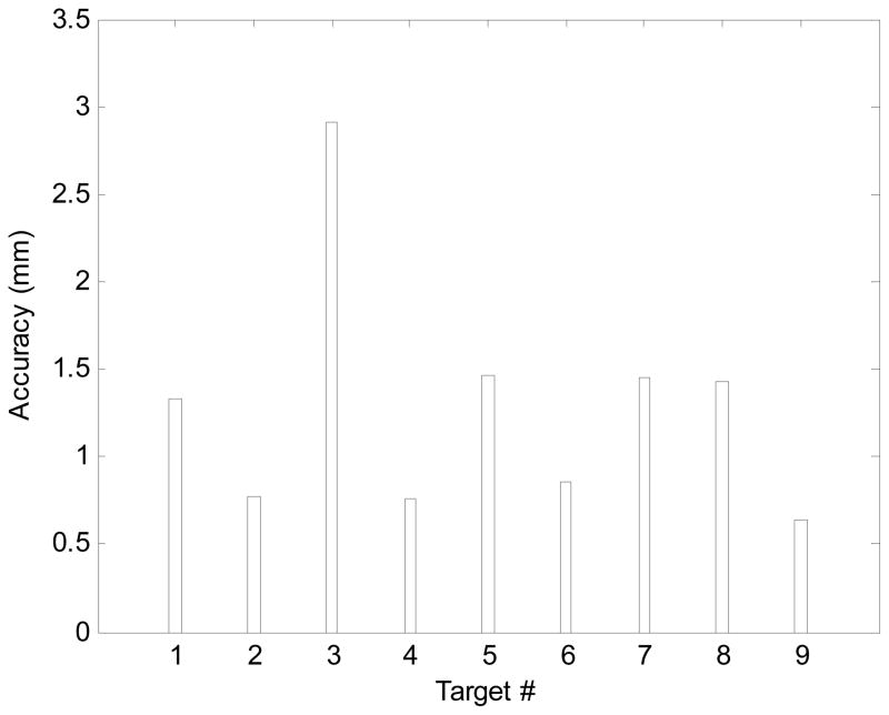
Figure 8 shows the distribution of the total error before needle insertion, i.e. the intrinsic error of the robotic system. The average error is 1.3 mm.
Fig. 8.
Total error of the robotic system distribution.
Overall needle placement error
The overall average error yielded by the experiment described in section 3.6, was 2.5 mm (STD=1.37 mm) which is within the acceptable range for prostate biopsy [21].
Due-to-insertion inaccuracy
As seen, the average overall needle placement error and the total error associated with the robotic system are known. With the assumption of no extrinsic error which is quite realistic in a phantom experiment, the total error due to insertion could be approximated as follows (it is a rough approximation since error components are vectors):
| (10) |
This implies that in our phantom experiments, due-to-insertion error is almost twice as large as the robotic system error.
Discussion
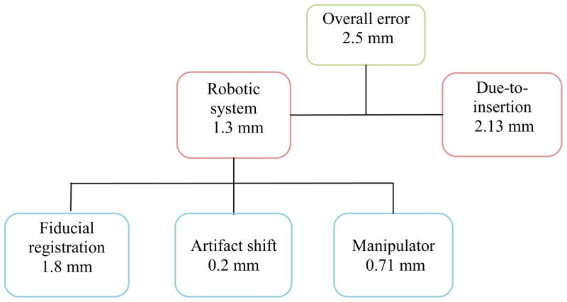
The overall needle placement error in phantom experiment was 2.5 mm which is acceptable for prostate cancer diagnosis. The overall error was broken into two parts: the error associated with the robotic system and the error caused due to insertion. Robotic system was responsible for 1.3 mm and the insertion was responsible for 2.13 mm, assuming the error components are orthogonal. The error due to the robotic system consists of the manipulator’s inaccuracy (0.71 mm), artifact shift (0.2 mm), and fiducial marker registration error (1.8 mm). The summation of absolute values of each part exceeds the total error (i.e. (1.8+0.7+0.2) mm = 2.7 mm >1.3 mm) because the error vectors may cancel out one another in some directions. Figure 9 shows this error distribution. The error due to the manipulator (robot) is relatively small compare to the fiducial registration error which indicates the effectiveness of the calibration process. The 2.13 mm error is an approximation of the due-to-insertion error and is mainly caused by needle deflection.
Fig. 9.
Summary of the error distribution (average values) of the studied robotic system in phantom MRI-guided prostate biopsy.
The calibration method proposed in this paper is somehow particular to this robot because parallel robots are unique in kinematics [32] and therefore, they require their own way of calibration. In fact, the conventional methods of calibration for serial robots are not applicable to them and for this reason, it was to the interest of this research. However, the methodology we proposed in this paper could still be customized for some other robot structures. This is due to the fact that our robot kinematic architecture has some features in common with some of its contemporary robots. To understand it better, consider the kinematic architecture of MrBot [11], SABiR [32], and the Twin Pantograph [33]. Similar to our robot, these parallel robots comprises of two identical planar mechanisms and by combining the motion of these planar linkages, angulations (pitch, roll, yaw) are generated, as well. More interestingly, the architecture of the planar mechanisms of these robots are almost the same (Fig. 10) but with different kinematic configurations. For example, the prismatic joints are replaced with revolute joints in Pantograph and SUBiR and or the location of prismatic joints are switched for the case of MrBot. Therefore, the study presented in this paper can be customized for those kinematic structures as well or for robots with similar idea in future.
Fig. 10.

The front (back) planar mechanism of different parallel robots: (a) our robot, (b) MrBot, (c) Twin Pantograph, and (d) SABiR. All of them have 5 joints and 5 linkages. In (a) and (b), two joints are prismatic, but in (c) and (d), all joints are revolutionary. This figure shows kinematic similarity within these robots.
Conclusions
In this study, different sources contributing into the error of robot-assisted prostate biopsy under MRI guidance were identified. In particular, the error caused by the robotic system was analyzed. All error components were quantified. A calibration method was proposed in order to minimize the robot’s inaccuracy as an important source of error. As the result, the overall error of the system in phantom experiment remained within the acceptable clinical range.
Acknowledgments
This work was funded by the U.S. National Institute of Health Grants 1R01CA111288, 5P01CA067165, R01CA124377, P41RR019703, P41EB015898, 5R01CA138586-02, AIST, and CIMIT 11-325. Gabor Fichtinger was supported as a Cancer Ontario Research Chair.
References
- 1.American Cancer Society. Cancer Facts and Figures. 2011 http://www.cancer.org.
- 2.Siegel R, Ward E, Brawley O, Jemal A. Cancer Statistics, 2011. The impact of eliminating socioeconomic and racial disparities on premature cancer deaths, Figure 1. doi: 10.3322/caac.20121. [DOI] [PubMed] [Google Scholar]
- 3.Eichler K, Hempel S, Wilby J, Myers L, Bachmann LM, Kleijnen J. Diagnostic value of systematic biopsy methods in the investigation of prostate cancer: a systematic review. Journal of Urology. 2006;175:1605–1612. doi: 10.1016/S0022-5347(05)00957-2. [DOI] [PubMed] [Google Scholar]
- 4.Yu KK, Hricak H. Imaging prostate cancer. Radiologic Clinics of North America. 2000;38(1):59–85. doi: 10.1016/s0033-8389(05)70150-0. [DOI] [PubMed] [Google Scholar]
- 5.D’Amico AV, Tempany CM, Cormack R, Hata N, Jinzaki M, Tuncali K, Weinstein M, Richie JP. Transperineal magnetic resonance image guided prostate biopsy. Journal of Urology. 2000;164(2):385– 387. [PubMed] [Google Scholar]
- 6.Hata N, Jinzaki M, Kacher D, Cormak R, Gering D, Nabavi A, Silverman SG, D’Amico AV, Kikinis R, Jolesz FA, Tempany CM. MR imaging-guided prostate biopsy with surgical navigation software: device validation and feasibility. Journal of Radiology. 2001;220(1):263–8. doi: 10.1148/radiology.220.1.r01jl44263. [DOI] [PubMed] [Google Scholar]
- 7.Susil R, Camphausen K, Choyke P, McVeigh E, Gustafson GG, Ning H, Miller R, Atalar E, Coleman C, Menard C. System for prostate brachytherapy and biopsy in a standard 1.5T MRI scanner. Magnetic Resonance in Medicine. 2004;52(3):683–687. doi: 10.1002/mrm.20138. [DOI] [PMC free article] [PubMed] [Google Scholar]
- 8.Chinzei K, Hata N, Jolesz FA, Kikinis R. MR compatible surgical assist robot: System integration and preliminary feasibility study. Medical Image Computing and Computer-Assisted Intervention (MICCAI) 2000;1935:921–930. [Google Scholar]
- 9.DiMaio SP, Pieper S, Chinzei K, Hata N, Haker SJ, Kacher DF, Fichtinger G, Tempany CM, Kikinis R. Robot-assisted needle placement in open MRI: system architecture, integration and validation. Computer Aided Surgery. 2007;12(1):15–24. doi: 10.3109/10929080601168254. [DOI] [PubMed] [Google Scholar]
- 10.Tadakuma K, DeVita LM, Plante JS, Shaoze Y, Dubowsky S. The experimental study of a precision parallel manipulator with binary actuation: With application to MRI cancer treatment. In Proc. IEEE International conference on Robotics and Automation (ICRA); Pasadena, USA. 2008. pp. 2503–2508. [Google Scholar]
- 11.Stoianovici D, Song D, Petrisor D, Ursu D, Mazilu D, Muntener M, Mutener M, Schar M, Patriciu A. MRI stealth robot for prostate interventions. Minimally Invasive Therapy and Allied Technologies. 2007;16(4):241–248. doi: 10.1080/13645700701520735. [DOI] [PMC free article] [PubMed] [Google Scholar]
- 12.Fischer GS, Iordachita I, Csoma C, Tokuda J, DiMaio SP, Tempany CM, Hata N, Fichtinger G. MRI-compatible pneumatic robot for transperineal prostate needle placement. IEEE/ASME Transactions on Mechatronics. 2008;13(3):295–305. doi: 10.1109/TMECH.2008.924044. [DOI] [PMC free article] [PubMed] [Google Scholar]
- 13.Goldenberg AA, Trachtenberg J, Kucharczyk W, Yi Y, Haider M, Ma L, Weersink R, Raoufi C. Robotic system for closed bore MRI-guided prostatic interventions. IEEE/ASME Transactions on Mechatronics. 2008;13(3):374–379. [Google Scholar]
- 14.van den Bosch MR, Moman MR, van Vulpen M, Battermann JJ, Duiveman E, van Schelven LJ, de Leeuw H, Lagendijk JJW, Moerland MA. MRI-guided robotic system for transperineal prostate interventions: proof of principle. Physics and Medical Biology. 2010;55(5):133–140. doi: 10.1088/0031-9155/55/5/N02. [DOI] [PubMed] [Google Scholar]
- 15.Su H, Shang W, Cole G, Harrington K, Fischer G. Design of a haptic device for mri-guided prostate needle brachytherapy. IEEE Haptics Symposium; Boston, USA. 2010. pp. 483–488. [Google Scholar]
- 16.Su H, Zervas M, Cole G, Furlong C, Fischer G. Real-time MRI-guided needle placement robot with integrated fiber optic force sensing. In Proc. IEEE International Conference on Robotics and Automation (ICRA); Beijing, China. 2011. pp. 1583–1588. [Google Scholar]
- 17.Bak JB, Landas SK, Haas GP. Characterization of prostate cancer missed by sextant biopsy. Clinical Prostate Cancer. 2003;2(2):115–118. doi: 10.3816/cgc.2003.n.019. [DOI] [PubMed] [Google Scholar]
- 18.Blumenfeld P, Hata N, DiMaio S, Zou K, Haker S, Fichtinger G, Tempany CM. Transperineal prostate biopsy under magnetic resonance image guidance: A needle placement accuracy study. Journal of Magnetic Resonance Imaging, vol. 2007;26(3):688–694. doi: 10.1002/jmri.21067. [DOI] [PubMed] [Google Scholar]
- 19.Tokuda J, Fischer GS, DiMaio SP, Gobbi DG, Csoma C, Mewes PW, Fichtinger G, Tempany CM, Hata N. Integrated navigation and control software system for MRI-guided robotic prostate interventions. Computerized Medical Imaging and Graphics. 2010;34(1):3–8. doi: 10.1016/j.compmedimag.2009.07.004. [DOI] [PMC free article] [PubMed] [Google Scholar]
- 20.Song S, Cho N, Ficsher G, Hata N, Tempany C, Fichtinger G, Iordachita I. Development of a pneumatic robot for MRI-guided transperineal prostate biopsy and brachytherapy: New approaches. Proceeding of IEEE International Conference Robotic and Automation (ICRA); Anchorage, USA. 2010. pp. 2580–2585. [DOI] [PMC free article] [PubMed] [Google Scholar]
- 21.Seifabadi R, Song SE, Krieger A, Cho NB, Tokuda J, Fichtinger G, Iordachita I. Robotic system for MRI-guided prostate biopsy: Feasibility of teleoperated needle insertion and ex vivo phantom study. International Journal of Computer Aided Radiology and Surgery (IJCARS) doi: 10.1007/s11548-011-0598-9. published online April 2011. [DOI] [PMC free article] [PubMed] [Google Scholar]
- 22.Song S, Hata N, Iordachita I, Fichtinger G, Tempany CM, Tokuda J. A Workspace-oriented Needle Guiding Robot for 3T MRI-guided Transperineal Prostate Intervention: Evaluation of In-bore Workspace and MRI Compatibility. International Journal of Medical Robotics and Computer Assisted Surgery. 2012 doi: 10.1002/rcs.1430. Accepted for publication. [DOI] [PMC free article] [PubMed] [Google Scholar]
- 23.Patriciu A, Petrisor D, Muntener M, Mazilu D, Schar MD. Stoianovici: automatic brachytherapy seed placement under MRI guidance. IEEE Transactions on Biomedical Engineering. 2007;54(8):1499–1506. doi: 10.1109/TBME.2007.900816. [DOI] [PMC free article] [PubMed] [Google Scholar]
- 24.Dehghan E, Salcudean SE. Needle insertion parameter optimization for brachytherapy. IEEE Transactions on Robotics. 2009;25(2):303–315. [Google Scholar]
- 25.Abolhassani N, Patel R, Ayazi F. Effects of different insertion methods on reducing needle deflection. International Conference of the IEEE EMBS; Lyon, France. 2007. pp. 491–494. [DOI] [PubMed] [Google Scholar]
- 26.Lagerburg V, Moerland MA, van Vulpen M, Lagendik JW. A new robotic needle insertion method to minimize attendant prostate motion. Radotherapy and Oncology. 2006;80(1):73–77. doi: 10.1016/j.radonc.2006.06.013. [DOI] [PubMed] [Google Scholar]
- 27.Xu H, Lasso A, Vikal S, Guion P, Krieger A, Kaushal A, Whitcomb LL, Fichtinger G. MRI-guided robotic prostate biopsy: A clinical accuracy validation. Medical Image Computing and Computer-Assisted Intervention (MICCAI) 2010;6363:383–391. doi: 10.1007/978-3-642-15711-0_48. [DOI] [PMC free article] [PubMed] [Google Scholar]
- 28.Hu Y, Carter T, Uddin H, Emberton M, Allen C, Hawkes D, Barratt D. IEEE Transactions on Medical Imaging. Modeling prostate motion for data fusion during image-guided interventions. Manuscript ID: TMI-2011–0093.R1 published online 2011. [DOI] [PubMed] [Google Scholar]
- 29.Masamune K, Fichtinger G, Patriciu A, Sakuma I, Dohi T, Stoianovici D. System for robotically assisted percutaneous procedures with computed tomography guidance. Journal of Computer Aided Surgery. 2001;6:370–383. doi: 10.1002/igs.10024. [DOI] [PubMed] [Google Scholar]
- 30.Peters T, Cleary K. Image-Guided Interventions: Technology and Applications. Springer; 2008. p. 447. [DOI] [PubMed] [Google Scholar]
- 31.Song SE, Cho NB, Iordachita I, Guion P, Fichtinger G, Whitcomb LL. A study of needle image artifact localization in confirmation imaging of MRI-guided robotic prostate biopsy. IEEE International Conference on Robotics and Automation (ICRA); Beijing, China. 2011. pp. 4834–4839. [DOI] [PMC free article] [PubMed] [Google Scholar]
- 32.Bebek O, Hwang MJ, Cavusoglu MC. IEEE/ASME Transaction on Mechatronics. Design of a Parallel Robot for Needle-Based Interventions on Small Animals. Published online on Aug 18 2011. [Google Scholar]
- 33.Sirouspour MR, DiMaio SP, Salcudean SE, Abolmaesumi P, Jones C. Haptic interface control: Design issues and experiments with a planar device. In Proc. IEEE Int. Conf. Robotics and Automation; USA. 2000. pp. 24–28. [Google Scholar]


