Abstract
Diagnosis of keratoconus has greatly improved from simple clinical diagnosis with the advent of better diagnostic devices like corneal topographers based on placido disc, elevation based topographers and lately optical coherence tomography (OCT). These instruments are quite sensitive to pick up early keratoconus, which could help refractive surgeons to avoid serious complications like ectasia following keratorefractive surgeries. Each of these instruments has their advantages and disadvantages; in spite of that each one of them has its own place in the clinical practice. Currently, placido disc based topographers are the most commonly used topographers all over the world. There are many different companies making such devices, which follow the different techniques and color for the display. Due to these differences they are not directly comparable to each other. Various quantitative indices based on these topographers have been suggested and validated by different authors to aid in the diagnosis and quantification of keratoconus. OCT with its higher resolution and deeper penetration has created its place in the diagnostic armamentarium for keratoconus.
Keywords: Corneal topography, imaging, keratoconus, optical coherence tomography, placido disc based topography
Keratoconus has certainly shown increased prevalence in recent time. It could be due to increase in the number of patients due to urbanization bringing along the allergic eye disease with it, which is known to have higher association with keratoconus. It could also be due to increase awareness in general ophthalmologist and refractive surgeons about keratoconus. However, the role of improved diagnostic devices to pick up the early disease cannot be undermined. These diagnostic devices have allowed us to diagnose the disease much earlier, and newer treatment modalities have increased our treatment options.
The clinical diagnosis of moderate to severe keratoconus is fairly easy when it presents with classical signs such as paracentral corneal thinning and protrusion, Vogt's striae, Fleischer ring, and scissoring reflex on retinoscopy.[1,2] Properly done laser-assisted in situ keratomileusis (LASIK) screening helps identify mild and forme fruste keratoconus which are known risk factors for post LASIK ectasia.[3] More recently, collagen cross-linking has brought the spotlight on early and forme fruste forms of the keratoconus. Collagen cross-linking, with its promise of arresting progression, enhances the need for early diagnosis of keratoconus, before the cornea becomes too thin to cross-link.
A variety of modern imaging modalities are available to diagnose subtle abnormalities in corneal curvature, thickness, and tissue architecture. Historically, imaging on keratoconic corneas was done using photographic placido disk studies, keratometry, photokeratoscopy, and finally computer-assisted videokeratoscopy. Corneal topography, one of the most important diagnostic imaging tools for keratoconus, has evolved through placido based devices to slit scanning and Scheimpflug imaging devices. Although placido disc based devices are still a highly sensitive tool to diagnose curvature changes on the anterior corneal surface, they might miss signs of early posterior corneal ectasia. Newer devices such as Scheimpflug imaging and optical coherence tomography (OCT) are useful adjuncts in imaging these early indicators of keratectasia.
Various quantitative indices have been suggested and validated by different authors to aid in the diagnosis and quantification of keratoconus.[2] In addition to diagnosis of keratoconus, precise corneal imaging modalities such as OCT[4] can also help in assessing the extent of ectasia, severity of thinning, and associated focal Descemet's membrane irregularities. These help in planning and follow-up of surgical interventions such as collagen cross-linking and lamellar keratoplasty. Additional imaging devices such as confocal microscopy, have a role in assessing the cellular architecture of virgin and cross-linked keratoconic corneas,[5,6] although their role in diagnosis is limited.
Review of Literature and Discussion
Computer-assisted videokeratoscopy/placido disc based corneal topography
Over the past couple of decades computer-assisted videokeratoscopes have become mandatory part in cornea and refractive surgery practice. Also, increasing use of multifocal and toric intraocular lens has opened a new avenue of usage of topography in cataract surgery practice too. The commonest topographers used in clinical practice are based on placido disk principles. There are many such devices currently available, although elevation based topography is rapidly gaining popularity too. The instruments used primarily consists of either a placido disk-type nose cone or a large placido disc consisting of dark and light rings of different number and sometimes even colors. Central camera captures the placido disk image reflecting from the thin tear film on the cornea into a computer based system, which analyzes the data. A good quality scan is a prerequisite for accurate curvature measurements, and requires a stable tear film and good patient fixation with adequate exposure of the cornea without lids obscuring most of the superior and inferior quadrants.
Topographic scales
The warmer colors (reds, oranges) on the map represent steeper cornea with higher keratometric diopteric power, the cooler colors (violets and blues) represent flatter cornea with lower diopteric power and greens and yellows represent colors found in normal cornea. These colors hold true for most “standard” scales. However, different topographers use different steps of colors, making it difficult to compare two different topographers. Topography of the same cornea would look different with the change in the steps of color. The smaller steps increase the sensitivity to pick up early keratoconus, but can falsely diagnose a normal cornea as keratoconic, whereas larger steps can miss out on the early changes. Hence, the topography should not be evaluated only based on the colors and the pattern [Fig. 1].
Figure 1.
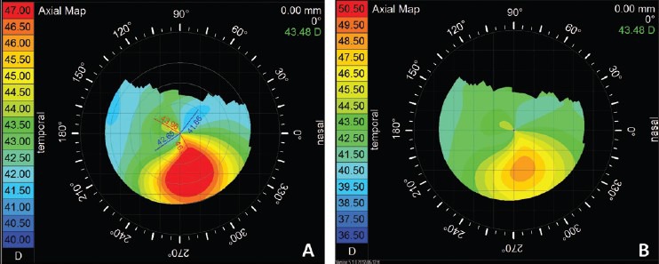
Topography of a same patient of keratoconus with different color steps, (a) having steps of 0.5 D and (b) having steps of 1.0 D, showing change in the pattern
Absoulte or standardized scale
An absolute scale map has the same fixed color-coding system for the particular instrument; same colors always represent the same dioptric steps, dioptric minimum and maximum. These maps are good for direct comparison of different maps (e.g., progression analysis in keratoconus) and for detecting gross pathologies. However, because the steps are in large increments (some system 0.5 D and other 1.5 D), their disadvantage is that they do not show subtle changes of curvature and can miss subtle local changes (e.g., early keratoconus).
Normalized or relative scale
Normalized maps have different color scales assigned to each map. The computer identifies the minimal and maximal dioptric values of the map and automatically distributes the range of colors. The computer contracts or expands its color range according to the range present in a given cornea. It has an advantage of showing more topographic details as the dioptric range assigned to each color generally is smaller compared to the absolute map. The disadvantage is that the colors of different maps from even a same cornea cannot be compared directly as they may have different steps and the meanings of colors are lost. A normal cornea may have different color and may look abnormal if interpreted only based on the colors.
Curvature/power map
Axial curvature map or sagittal curvature map
It is the most commonly used map. It measures the curvature at a certain point on the corneal surface in axial direction relative to the center. It is helpful in evaluating the overall shape of the cornea. The biggest advantage of this map is that the pattern diagnosis of a map can be done and a map can be classified into normal or abnormal. Typical topographic patterns of various diseases can be used to easily identify them, for example, asymmetric bow tie pattern with the skewed radial axis in keratoconus and “butterfly” or “crab-claw” pattern in pellucid marginal degeneration. Disadvantage of this map is that the smaller or local irregularity can be missed and the peripheral curvature measurement is not very accurate.
Tangential curvature map or instantaneous map or meridional curvature map
It measures the curvature at a certain point on the corneal surface in meridional direction relative to the other points on the particular ring. Tangential curvature maps are more sensitive in detecting local curvature change, hence can be useful in detecting early changes, which might have been missed by the axial map. It is more accurate than the axial map in corneal periphery. The disadvantage is that it is subjected to more variation as it detects the localized changes and hence for the same disease we may not have similar topography making a pattern diagnosis difficult.
Elevation map
Elevation is not measured directly by placido based topographers, but certain assumptions allow the construction of elevation maps. Elevation of a point on the corneal surface displays the height of the point (in micron) on the corneal surface relative to a reference surface. The reference surface in most instruments is a sphere, however some systems can also allow various other shapes like ellipsoid, toric ellipsoid, torus, etc., as a reference surface. Best mathematical approximation of the actual corneal surface called best-fit sphere is calculated by instrument software for every elevation map separately. The size or the radius of curvature of the best-fit sphere would differ from the test to test in a same individual also. The same surface may appear to be different when mapped against different reference surfaces. Hence, directly comparing two elevation maps that likely have slightly different best-fit spheres as reference values is difficult, and comparison only can be intuitive. Some elevation based topographers do have an option of changing and thus matching the radius of curvature of best-fit sphere of two different readings/maps. Along with this it is also important to check for the quality of scan using their raw data or “Quality Score”. Also such direct comparison requires the x-y alignment of two maps, which some elevation based topographers are capable of doing.
Statistical indices
Different commercially available systems have given different names to indices, but they are calculated in similar way and perform similar function. Common indices are as follows: Simulated keratometry (SimK): Equivalent to keratometry and is calculated at steepest axes and axes 90° to it from the average power at 3 mm zone. Difference is taken as cylinder (Cyl). It can also measure flattest axes (MinK). Surface asymmetry index (SAI): Difference in corneal power between points on the same ring 180° apart, which can quantify the progression of keratoconus etc. surface regularity index (SRI): Points in central 4.5 mm are compared with their surrounding points. High values suggest high irregularity in the surface. inferior-superior value (I-SV): Calculated from the power difference between five inferior points and five superior points 3 mm form center at 30° intervals. Many other indices specific for each instrument exist, for example, corneal uniformity index (CUI), predicted corneal acuity (PCA), and point spread function (PSF), etc. Note that patients with normal corneal indexes can have poor vision caused by disturbances in any other part of the optical system of the eye.
Definitions of keratoconus
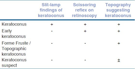
Rabinowitz[7] has developed a classification scheme based on axial topography and clinical signs to detect keratoconic subtypes [Table 2]. “Keratoconus” is a clinical disease that is detectable at the slit-lamp through obvious clinical signs such as stromal thinning and is associated with a typical topographic pattern (asymmetric bow tie with a skewed radial axis). In “early keratoconus”, there are no slit-lamp findings, but scissoring is evident on retinoscopy. The typical topography (asymmetric bow tie with a skewed radial axis) is also present. “Forme fruste keratoconus” or “topographic keratoconus” presents with no slit-lamp findings or scissoring on retinoscopy, but the typical topography (asymmetric bow tie with a skewed radial axis) is once again present. “Keratoconus suspect” is a catch all term to indicate a patient with inferior or central steepening on topography that the clinician suspects may progress to keratoconus. The term is not synonymous with subclinical keratoconus, because the practitioner only knows it is subclinical once it has progressed to keratoconus. Many patients labeled as keratoconus suspects never develop clinical keratoconus.
Table 2.
Definitions of various stages of keratoconus
Topographic pattern recognition: Normal versus keratoconus
Corneal topography in normal corneas
The topographic patterns both eyes of an individual often show mirror-image symmetry. This phenomenon is called enantiomorphism. Rabinowitz et al.,[7] described the distribution of axial curvature map topographic patterns in normal eyes which are following; round, oval, superior steepening, inferior steepening, symmetric bow tie, symmetric bow tie with skewed axes, asymmetric bow tie with inferior steepening, asymmetric bow tie with superior steepening, asymmetric bow tie (AB) with skewed radial axes (SRAX) and irregular. Skewing of more than 30° is described as significantly abnormal [Fig. 2].
Figure 2.
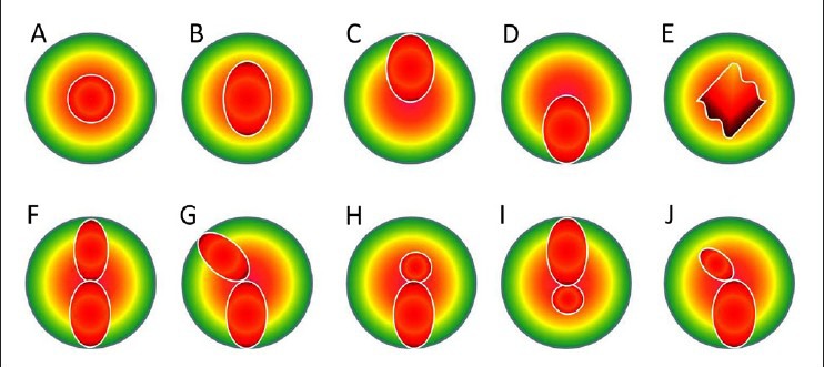
Classification of various patterns on axial map of placido based topography. Top A, round; B, oval; C, superior steepening; D, inferior steepening; E, irregular; F, symmetric bow tie; G, symmetric bow tie with skewed radial axes; H, asymmetric bow tie with inferior steepening (AB/IS); I, asymmetric bow tie with superior steepening; J, asymmetric bow tie with skewed radial axes (AB/SRAX)
Corneal topography in keratoconus
Keratoconus has three characteristics seen on axial topographic map that are not present in normal individuals: An increased area of corneal power surrounded by concentric areas of decreasing power, inferior-superior power asymmetry, and skewing of the steepest radial axes above and below the horizontal meridian; asymmetric bow tie with skewed radial axes (AB/SRAX) pattern. The AB/SRAX pattern only occurs in 0.05% of the normal patient population,[8] but it is almost universal in patients with keratoconus. Such individuals, even in the absence of clinical evidence of keratoconus, should be treated with a high degree of suspicion. Few of the central cones can show symmetric bow tie pattern, but usually the inferior loop is larger. Rarely the central cone can show only central steepening without any bow tie pattern, but the K-value usually would be steep (>47.20 D).
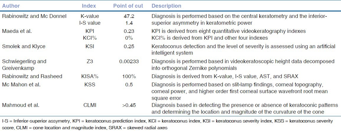
Several commonly known indices are of Rabinowitz/Mc Donnel, Maeda/Klyce, Rabinowitz/Rasheed's KISA%, etc. The Rabinowitz/Mc Donnel[8] diagnostic criteria consists of two topography derived indices, which are as follows; central K-value > 47.20 D and Inferior-Superior asymmetry (I-S value) > 1.4 D. Rabinowitz/Rasheed's described KISA% to diagnose keratoconus.[9] KISA% index is usually applied to the axial map. It uses four indices on the topography.
![]()
K-value here is central keratomertic value in access of 47.2 D (i.e., K-47.2). If value is less then or 47.2, it is replaced by 1. I-S or inferior-superior asymmetry, AST calculated from (Sim K1-SimK2), SRAX is calculated from 180-the angle between two steep axis above and below the horizontal meridian (smaller of the two angles). To amplify any abnormality, the value 1 was substituted in the equation whenever a calculated index has a value of less than 1 [Fig. 3].
Figure 3.
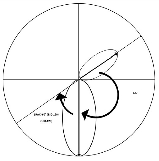
Calculation of SRAX: SRAX is calculated from 180-the angle between two steep axis above and below the horizontal meridian (smaller of the two angles). In this example two steep axis form 120° angle, hence SRAX = 60 (180−120)
KISA% > 100% is considered as highly suggestive of keratoconus. Rabinowitz and Rasheed,[9] who demonstrated that with a cut-off value of 100%, KISA% determined the correct diagnosis in 99.6% of cases. Similarly, Sedghipour et al.,[10] reported sensitivity of 96%, specificity of 100%, positive predictive value of 100%, and negative predictive value of 96.15% for the diagnosis of keratoconus. However, KISA% may not be very sensitive when used for keratoconus suspect or very early keratoconus as evident by study from Li et al.,[11] where they could only pick up 68.9% keratoconus cases. With lowering cut-off value to 60−100% it may help to detect early keratoconus cases too. Other indices are KPI (keratoconus prediction index) and KCI% (keratoconus index) by Maeda et al[12], KSI (keratoconus severity index) by Smolek and Klyce[13], Z3 using Zernikes polynomials by Schwiegerling and Greivenkamp[14], KSS (keratoconus severity score) by Mc Mahon et al.[15] and CLMI (cone location and magnitude index) by Mahmoud et al.[16] [Table 1].
Table 1.
Index based system for diagnosis of keratoconus
Topographic pseudokeratoconus
The most common culprit is contact lens wear (both hard and soft), which induces patterns of inferior steepening that may be very difficult to distinguish from keratoconus. These patterns, however, disappear with time after contact lens wear is discontinued. Topographic pseudokeratoconus may also result from technical errors during topographic procedure, such as inferior eyeball compression while trying to retract the eye lids, misalignment of the eye with inferior or superior rotation of the eye ball [Fig. 4], and incomplete digitization of mires, causing formation of dry spots, which simulates inferior steepening. Other conditions like pellucid marginal degeneration [Fig. 5], Terrien's marginal degeneration, keratoglobus, scarred cornea, and previous ocular surgery.
Figure 4.
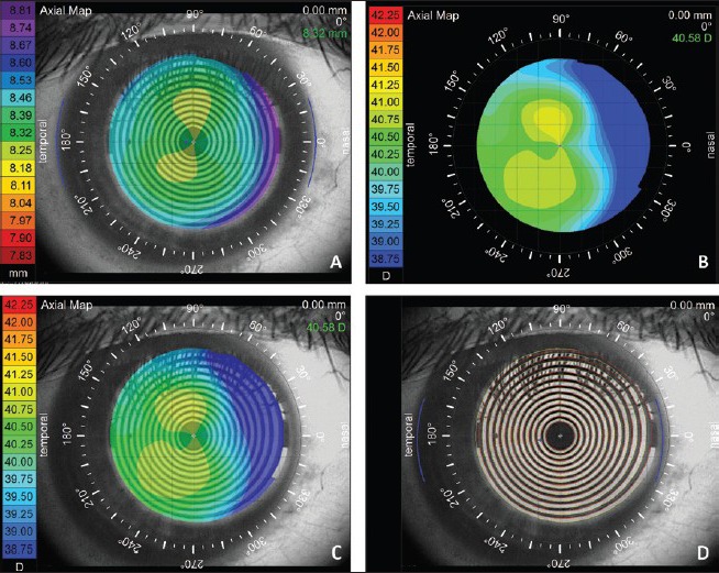
Pseudokeratoconus: This figure shows the importance of misalignment of the normal eye mimicking a keratoconus. (a) Shows axial topography of a normal subject of with the rule astigmatism. (b) The same subject with the misalignment showing skewed radial axis mimicking keratoconus. (c) An overlay of the eye image and (d) mires overlay show apparent misalignment
Figure 5.
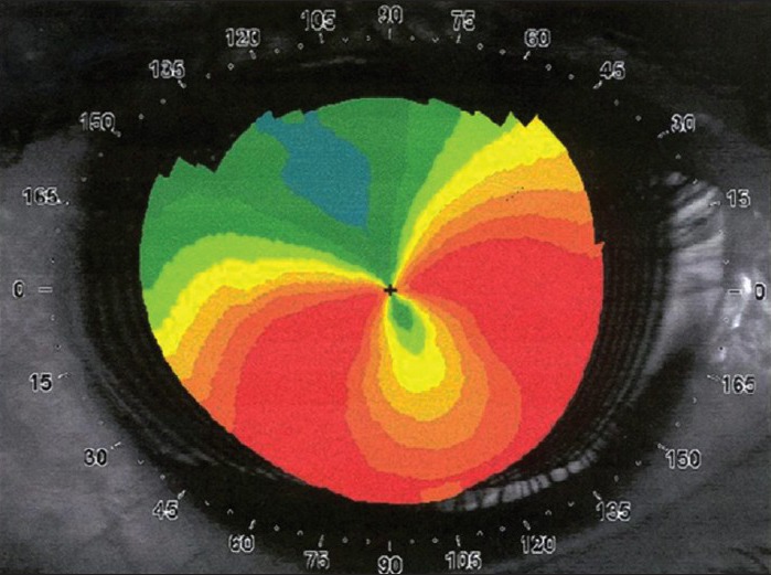
Axial curvature map showing typical “crab claw”/“butterfly wing” pattern of pellucid marginal degeneration, which may mimic eccentric keratoconus. A careful slit-lamp examination and elevation based topography may help to differential it with keratoconus
Corneal OCT
The measurement of corneal thickness (pachymetry) has important diagnostic and surgical applications in keratoconus and other ectasias. Unlike ultrasound pachymeters, which provide only spot pachymetry, the use of OCT technology to obtain a precise pachymetric map of the cornea was first described by Li et al., in 2006.[4] The OCT is a noncontact imaging modality that provides a high resolution cross-sectional analysis of the corneal thickness. Prior to the advent of anterior segment OCT, several investigators have tried imaging the cornea using commercial retinal OCT scanners. Although retinal OCT scanners can measure the central corneal thickness, pachymetric mapping is not possible due to slow speed of scanning and consequent motion artefacts.[4]
A variety of high speed OCT scanners are now available that can image and measure the corneal thickness. Fourier domain technology provides the advantage of faster scan acquisition speed with greater axial resolution.[17] Li et al., suggested some quantitative parameters to assess diagnostic utility of OCT in keratoconus.[18] The authors identified five OCT pachymetric parameters, which showed high sensitivity and specificity in the diagnosis of established keratoconus [Fig. 6].
Figure 6.
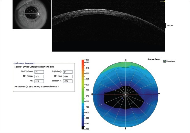
Pachymetric map of Optovue RTVue optical coherence tomography (OCT) showing significant thinning in the paracentral cornea. Almost all quantitative indices exceed the cut off limits confirming the diagnosis of keratoconus. Line scan also shows hyperreflectivity in the anterior stroma secondary to mild scarring
Minimum-median. (cut off value: 62.6 microns).
The I-S: The average thickness of the inferior (I) octant minus that of the superior (S) octant (cut off value: 31.3 microns).
The IT-SN: The average thickness of the IT octant minus that of the SN octant (cut off value: 48.2 microns).
Minimum (cutoff value 491.6 microns).
Vertical location of the minimum. Locations superior to the corneal vertex had positive values and locations inferior to the vertex had negative values (cut off value: 716 microns).
Recently, epithelial thickness profile maps using Fourier domain OCT have been shown to be useful in detecting subtle epithelial changes, which have been to be a sign of early keratoconus.[19] Apical epithelial thinning over the apex of the cone in early ectasia can mask topographic changes on the anterior corneal surface. High frequency ultrasound has also been, in the past, shown to demonstrate precise epithelial thickness profiles that were useful in diagnosis of early keratoconus; but Fourier domain OCT provides a simpler noninvasive means to perform a similar analysis of the corneal epithelium [Fig. 9].[20]
Figure 9.
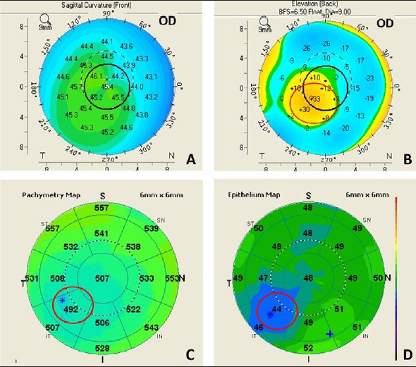
Epithelial profile on OCT: Apical epithelial thinning over the apex of the cone in early ectasia can mask topographic changes on the anterior corneal surface. (a) Shows axial map of a forme fruste keratoconus showing minimal changes of keratoconus on the anterior surface, (b) shows the posterior elevation of the same eye showing significant elevation, (c) shows the total corneal pachymetry on Optovue RTVue OCT along with (d) epithelial thickness map, showing localized epithelial thinning masking the cone
The OCT is also a very useful tool in studying the optical characteristics of the cornea after surgical interventions such as collagen cross-linking.[21] In the first few weeks after cross-linking, a faint hyperreflectivity is noted in the anterior stroma. At around 1 month postoperatively, a distinct demarcation is noted between the cross-linked and non-cross-linked areas of the cornea [Fig. 7]. This demarcation line usually fades by 3 months and is sometimes replaced, in some corneas, with faint irregular hyperreflective lines in the deep stroma. OCT can be extremely useful tool to see the irregularity of Descement's membrane due to previous hydrops, which in turn can help us in decision making regarding the surgical interventions like deep anterior lamellar keratoplasty (DALK) [Fig. 8]. High resolution hand held OCT can be a quite useful tool to know the extent of residual cornea in case of DALK. OCT can also show the corneal stroma posterior to intracorneal ring segments. Post keratoplasty OCT can help us to study the wound architecture and posterior wound apposition to decide about the suture removal.
Figure 7.
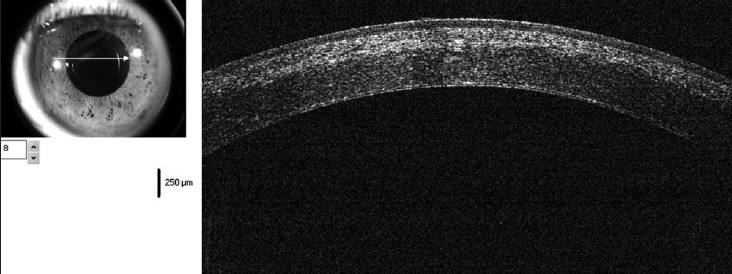
OCT showing distinct demarcation line at the junction of cross-linked and non-cross-linked cornea at 3 weeks postoperative visit
Figure 8.
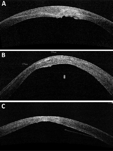
(a-c) Various morphologies of Descemet's membrane (DM) irregularities seen in patients with keratoconus, suggestive of possible old hydrops. Presence of DM irregularities may affect choice of surgical procedure when considering intervention such as deep lamellar keratoplasty
Conclusions
To summarize; a properly performed, good quality corneal topography is an excellent tool to diagnose keratoconus. The topographic indices can help us to detect and classify early and borderline cases of keratoconus. The placido disc based devices are very useful tool to diagnose keratoconus, however they do not show any changes on the posterior surface of the cornea. Newer, diagnostic devices like elevation based topographers and OCT can help us to visualize the posterior surface of cornea and can also give an accurate idea about the pachymetry of entire cornea. These newer modalities can help us diagnose keratoconus in preclinical stage, thus allowing an early treatment.
Footnotes
Source of Support: Nil
Conflict of Interest: None declared.
References
- 1.Krachmer JH, Feder RS, Belin MW. Keratoconus and related noninflammatory corneal thinning disorders. Surv Ophthalmol. 1984;28:293–322. doi: 10.1016/0039-6257(84)90094-8. [DOI] [PubMed] [Google Scholar]
- 2.Rabinowitz YS. Keratoconus. Surv Ophthalmol. 1998;42:297–319. doi: 10.1016/s0039-6257(97)00119-7. [DOI] [PubMed] [Google Scholar]
- 3.Randleman JB, Russell B, Ward MA, Thompson KP, Stulting RD. Risk factors and prognosis for corneal ectasia after LASIK. Ophthalmology. 2003;110:267–75. doi: 10.1016/S0161-6420(02)01727-X. [DOI] [PubMed] [Google Scholar]
- 4.Li Y, Shekhar R, Huang D. Corneal pachymetry mapping with high-speed optical coherence tomography. Ophthalmology. 2006;113:792–9.e2. doi: 10.1016/j.ophtha.2006.01.048. [DOI] [PMC free article] [PubMed] [Google Scholar]
- 5.Mazzotta C, Balestrazzi A, Traversi C, Baiocchi S, Caporossi T, Tommasi C, et al. Treatment of progressive keratoconus by riboflavin-UVA-induced cross-linking of corneal collagen: Ultrastructural analysis by Heidelberg Retinal Tomograph II in vivo confocal microscopy in humans. Cornea. 2007;26:390–7. doi: 10.1097/ICO.0b013e318030df5a. [DOI] [PubMed] [Google Scholar]
- 6.Ku JY, Niederer RL, Patel DV, Sherwin T, McGhee CN. Laser scanning in vivo confocal analysis of keratocyte density in keratoconus. Ophthalmology. 2008;115:845–50. doi: 10.1016/j.ophtha.2007.04.067. [DOI] [PubMed] [Google Scholar]
- 7.Rabinowitz YS, Yang H, Brickman Y, Akkina J, Riley C, Rotter JI, et al. Videokeratography database of normal human corneas. Br J Ophthalmol. 1996;80:610–6. doi: 10.1136/bjo.80.7.610. [DOI] [PMC free article] [PubMed] [Google Scholar]
- 8.Rabinowitz YS, McDonnell PJ. Computer-assisted corneal topography in keratoconus. Refract Corneal Surg. 1989;5:400–8. [PubMed] [Google Scholar]
- 9.Rabinowitz YS, Rasheed K. KISA% index: A quantitative videokeratography algorithm embodying minimal topographic criteria for diagnosing keratoconus. J Cataract Refract Surg. 1999;25:1327–35. doi: 10.1016/s0886-3350(99)00195-9. [DOI] [PubMed] [Google Scholar]
- 10.Sedghipour MR, Sadigh AL, Motlagh BF. Revisiting corneal topography for the diagnosis of keratoconus: Use of Rabinowitz's KISA% index. Clin Ophthalmol. 2012;6:181–4. doi: 10.2147/OPTH.S24219. [DOI] [PMC free article] [PubMed] [Google Scholar]
- 11.Li X, Yang H, Rabinowitz YS. Keratoconus: Classification scheme based on videokeratography and clinical signs. J Cataract Refract Surg. 2009;35:1597–603. doi: 10.1016/j.jcrs.2009.03.050. [DOI] [PMC free article] [PubMed] [Google Scholar]
- 12.Maeda N, Klyce SD, Smolek MK, Thompson HW. Automated keratoconus screening with corneal topography analysis. Invest Ophtalmol Vis Sci. 1994;35:2749–57. [PubMed] [Google Scholar]
- 13.Smolek MK, Klyce SD. Current keratoconus detection methods compared with a neural network approach. Invest Ophthalmol Vis Sci. 1997;38:2290–9. [PubMed] [Google Scholar]
- 14.Schwiegerling J, Greivenkamp JE. Keratoconus detection based on videokeratoscopic height data. Optom Vis Sci. 1996;73:721–8. doi: 10.1097/00006324-199612000-00001. [DOI] [PubMed] [Google Scholar]
- 15.McMahon TT, Szczotka-Flynn L, Barr JT, Anderson RJ, Slaughter ME, Lass JH, et al. CLEK Study Group. A new method for grading the severity of keratoconus: The keratoconus severity score (KSS) Cornea. 2006;25:794–800. doi: 10.1097/01.ico.0000226359.26678.d1. [DOI] [PubMed] [Google Scholar]
- 16.Mahmoud AM, Roberts CJ, Lembach RG, Twa MD, Herderick EE, McMahon TT CLEK Study Group. CLMI: The cone location and magnitude index. Cornea. 2008;27:480–7. doi: 10.1097/ICO.0b013e31816485d3. [DOI] [PMC free article] [PubMed] [Google Scholar]
- 17.Li Y, Tang M, Zhang X, Salaroli CH, Ramos JL, Huang D. Pachymetric mapping with Fourier-domain optical coherence tomography. J Cataract Refract Surg. 2010;36:826–31. doi: 10.1016/j.jcrs.2009.11.016. [DOI] [PMC free article] [PubMed] [Google Scholar]
- 18.Li Y, Meisler DM, Tang M, Lu AT, Thakrar V, Reiser BJ, et al. Keratoconus diagnosis with optical coherence tomography pachymetry mapping. Ophthalmology. 2008;115:2159–66. doi: 10.1016/j.ophtha.2008.08.004. [DOI] [PMC free article] [PubMed] [Google Scholar]
- 19.Li Y, Tan O, Brass R, Weiss JL, Huang D. Corneal epithelial thickness mapping by fourier-domain optical coherence tomography in normal and keratoconic eyes. Ophthalmology. 2012;119:2425–33. doi: 10.1016/j.ophtha.2012.06.023. [DOI] [PMC free article] [PubMed] [Google Scholar]
- 20.Reinstein DZ, Archer TJ, Gobbe M. Corneal epithelial thickness profile in the diagnosis of keratoconus. J Refract Surg. 2009;25:604–10. doi: 10.3928/1081597X-20090610-06. [DOI] [PubMed] [Google Scholar]
- 21.Doors M, Tahzib NG, Eggink FA, Berendschot TT, Webers CA, Nuijts RM. Use of anterior segment optical coherence tomography to study corneal changes after collagen cross-linking. Am J Ophthalmol. 2009;148:844–51.e2. doi: 10.1016/j.ajo.2009.06.031. [DOI] [PubMed] [Google Scholar]


