

Abstract
There is critical clinical demand for tissue-engineered (TE), three-dimensional (3D) constructs for tissue repair and organ replacements. Current efforts toward this goal are prone to necrosis at the core of larger constructs because of limited oxygen and nutrient diffusion. Therefore, critically sized 3D TE constructs demand an immediate vascular system for sustained tissue function upon implantation. To address this challenge the goal of this project was to develop a strategy to incorporate microchannels into a porous silk TE scaffold that could be fabricated reproducibly using microfabrication and soft lithography. Silk is a suitable biopolymer material for this application because it is mechanically robust, biocompatible, slowly degrades in vivo, and has been used in a variety of TE constructs. We report the fabrication of a silk-based TE scaffold that contains an embedded network of porous microchannels. Enclosed porous microchannels support endothelial lumen formation, a critical step toward development of the vascular niche, while the porous scaffold surrounding the microchannels supports tissue formation, demonstrated using human mesenchymal stem cells. This approach for fabricating vascularized TE constructs is advantageous compared to previous systems, which lack porosity and biodegradability or degrade too rapidly to sustain tissue structure and function. The broader impact of this research will enable the systemic study and development of complex, critically-sized engineered tissues, from regenerative medicine to in vitro tissue models of disease states.
Keywords: silk, biodegradable, microfabrication, vascularization, tissue engineering
1. Introduction
There is significant clinical demand for functional engineered biomaterial constructs capable of regenerating large tissues and complex organs. A major obstacle in realizing this goal is the diffusion limit of oxygen and nutrients into the bulk of these systems. Tissue engineered (TE) constructs that exceed dimensions beyond several hundred micrometers fail to fully integrate with host tissue over the long-term due to lack of blood perfusion, resulting in loss of function and necrosis.[1–3] Oxygen and nutrients are supplied to tissues naturally by the microvascular system, which is composed of branching, small diameter blood vessels. Microvascular blood vessels are lined with a single layer of endothelial cells that mediate both passive and active transport of oxygen and nutrients across the vessel wall into the surrounding tissue.[4, 5] The mechanisms that control microvascular network assembly and nutrient delivery are complex and challenging to recreate in vitro.
One promising strategy for recapitulating the structure and function of the microvascular system within TE scaffolds involves microfluidic fabrication methods. These methods have been used to successfully pattern synthetic polymer materials and natural polymer hydrogels. Synthetically-derived polymer materials such as polydimethylsiloxane, polylactide-co-glycolide, polyglycerol sebacate, polycarbonate, polycaprolactone, polystyrene and polyurethane have been patterned with microfluidic channels that replicate microvascular-like dimensions that could be perfused with physiologic blood flow rates and blood vessel wall shear stresses.[6–11] While synthetic materials support microvascular-like perfusion systems, there are concerns of long-term in vivo function and integration because materials such as polydimethylsiloxane, polycarbonate, and polystyrene lack cellular recognition sites and resist remodeling by the host tissue and materials such as polylactide-co-glycolide can have inflammatory degradation products.[12] Furthermore, many synthetic material systems lack a porous bulk matrix surrounding the microchannels, which significantly limits utility in engineering tissues around the microchannels. Efforts have been reported to build porous micropatterned synthetic material systems, however the pores were small in diameter and cell infiltration into the bulk space was not demonstrated.[9, 13]
Research efforts have also focused on building microfluidic systems using natural polymer hydrogels, including collagen, fibrin, and alginate.[14–16] These materials allow nutrient transport across the microchannel walls and cell proliferation in the bulk space around the microchannels, making these systems more appropriate than synthetic materials for regenerative medicine applications. A perfusable microchannel using collagen type I as the bulk material has been developed in which endothelial cells proliferated to confluence along the microchannel wall and dynamically regulated diffusion of fluorescent molecules across the microchannel wall in response to inflammatory cues.[14] Branching networks within collagen and fibrin gels supported endothelial cells within the microchannels and fibroblast cultures in the bulk space surrounding the microchannels.[15] While these biologically-derived systems enabled nutrient transport, these materials lack mechanical strength and rapidly degrade upon implantation.[17–20] Furthermore, most of these systems are fabricated from hydrogels, which require that the parenchymal cell type be incorporated into the bulk matrix during the casting step. This requirement limits the shelf life of the system and requires that scaffold assembly be performed under sterile conditions.
In contrast to non-porous synthetic elastomeric and nano-porous hydrogel materials, patterned microporous scaffolds would accommodate regimes for building tissue equivalents in vitro. Microporous scaffolds refer to constructs that are built using techniques such as salt-leaching and freeze-drying and the scaffold pores are interconnected with diameters that generally range between 100 and 800 um. These types of scaffolds are widely used in tissue engineering and regenerative medicine because their ultrastructure is conducive for supporting critically-sized tissue formation.[21]
An exemplary material for building microporous scaffolds is silk fibroin because it is mechanically robust, biocompatible, and slowly degrades in vivo.[22] Previous studies have demonstrated successful patterning of non-porous silk films with branching microfluidic channels that could be perfused and supported endothelial cell proliferation.[23, 24] In the present study, we build upon this previous work to overcome limitations such as the lack of porous microchannel walls that allow for nutrient delivery and a microporous bulk space that allows for tissue formation. The objective of this study was to develop a fabrication method for building porous microchannels into a microporous silk scaffold that slowly degrades in vivo and is structurally robust. We report the development of such a porous silk-based perfusion system in which the microchannels are patterned into salt-leached silk sponges using soft-lithography microfabrication techniques. The porous channels are enclosed by bonding a flat porous scaffold to the micropatterned scaffold using a biologically-derived tissue adhesive. In the open channel configuration, human microvascular endothelial cells (hMVECs) proliferated on all surfaces of the channel walls. After the porous channels were enclosed, the endothelial cells underwent lumen formation. Furthermore, the utility of this porous silk perfusion system to support complex tissue formation was demonstrated by co-culturing endothelial cells in the porous microchannels with adult human mesenchymal stem cells (hMSCs) in the bulk scaffold. This system is a potential new tool for developing engineered tissues for whole organ replacement and for disease and drug delivery tissue models ex vivo, particularly where sustained structure and function over months if not years is critical to the discovery process
2. Results and Discussion
Due to significant clinical demand, the field of regenerative medicine develops complex tissues and whole organ replacements to treat and cure debilitating injuries and illnesses. A major obstacle in engineering large, complex tissues is supplying the entire construct with sufficient oxygen and nutrients. In the body, oxygen and nutrients are delivered by the microvascular system, which is composed of a branching network of small blood vessels that transport material from the blood into the surrounding tissue. In order to successfully build complex tissues ex vivo, a similar system must be recapitulated within engineered constructs.
2.1. Fabrication of Microchannels in a Porous Silk Scaffold
Microchannel master patterns were transferred to polydimethylsiloxane (PDMS) molds in one of two ways, depending on the shape of the channel profile. For channels with rectangular cross-section, a SU-8 negative photoresist was patterned with photolithography (Figure 1A). For channels with a semi-circular cross-section, thin film silicon nitride silicon wafers coated with a SPR220 positive photoresist were patterned with sequential photolithography, reactive ion etching, and wet etching steps. Porous microchannels were fabricated using a composite scaffold made from a porous silk film and salt-leached sponge. First, the porous silk film was cast onto the patterned PDMS mold and water annealed, followed by salt-leached sponge assembly (Figure 1B). This fabrication method resulted in a platform where the microchannel walls contained pores ranging from 0.5 to 3.5 μm in diameter and a bulk space around the channels that contained 100–350 μm diameter, interconnected pores. The scaffold was removed from the PDMS mold and the bulk thickness was reproducibly trimmed to suit the needs of the desired tissue engineering application (Figure 1C). The lower limit of this trimming method resulted in scaffolds that were 500 μm thick. Moreover, the scaffold was mechanically robust with an elastic modulus of 77 MPa and yield modulus of 26 kPa under tension.
Figure 1.

Schematic of micropatterned porous silk scaffold fabrication. (A) Microfluidic channel patterns are transferred from a silicon wafer to polydimethyl siloxane (PDMS) using standard photolithography and soft lithography techniques. The PDMS mold is trimmed to the desired shape and size. (B) A porous silk film is cast over the PDMS mold and water annealed to induce β-sheet crystallinity. An aqueous-derived salt leached silk scaffold is assembled over the silk film. The scaffold is cured and removed from the PDMS mold. SEM images show patent microchannels on the surface of the scaffold and 100–350 um diameter interconnected pores in the bulk of the scaffold. (C) The scaffold thickness is trimmed by swiping a blade across the top of a positioning mold, which removes the bit of exposed scaffold. This mold allows for tunable control over the resulting thickness of the scaffold by changing the height of the positioning block.
Using this method, microchannel cross-section shape and dimensions could be varied, the goal being to recapitulate the various morphological characteristics of vascular branching systems found throughout the body. Two different channel cross-sections were obtained by altering the wafer etching protocols (Figure 2A). For the rectangular microchannels, channel heights were dictated by the photoresist thickness and for the semi-circular microchannels, channel heights and widths were adjusted by the duration of the chemical wet etch. For rectangular microchannels, photoresist height that exceeded 100 μm resulted in incomplete detachment of the scaffold from the PDMS mold while 25 μm high channels had porous walls and detached completely. As a result, channel heights of 25 μm were used for subsequent cell culture experiments (Figure 2B). Given that physiologic microvasculature vessels have diameters that range between 10–50 μm, a channel height of 25 μm was considered appropriate. Fluorescence microscopy was used to measure the channel dimensions. Image analysis revealed that the average channel height increased by 1–10% while the channel width shrank 20–35% when compared to the silicon wafer mold dimensions (Figure 2C). We attribute this effect to the salt-leached scaffold assembly step. After the silk film was cast on the PDMS mold, a silk sponge was assembled over the mold. During this step, the forming scaffold coupled with the porous silk film. This coupling between the salt-leeched sponge and porous silk film caused the silk film to undergo mechanical stresses and contract upon detachment from the PDM mold. In future studies the shrinkage/expansion of the microchannel dimensions should be compensated for in the master mold in order to achieve the desired final dimensions. Extensive branching patterns and a wide range of channel widths ranging from as low as 25 μm up to 300 μm were obtained by altering the dimensions of features on the photomask (Figure 2D). After detachment, the microchannel edges and sharp branching points remained patent (Figure 2E). The physiology of the microvascular system is dependent on the structure of the vessel dimensions and its branching hierarchy, underscoring the importance for the microchannels in the silk scaffold system to mimic these structural parameters.[25, 26] Moreover, microvascular topography and morphology is variable among tissue types [27, 28] making the method presented here appealing because of its adaptability.
Figure 2.

Morphology of porous silk microchannels. (A) Channel profiles can be half-moon or rectangular (scale bars = 50 μm). (B) The optimal microchannel height is 25 μm. Microchannels with heights greater than 25 μm tear during removal from the PDMS mold as demonstrated by 125 μm high channels (scale bars = 50 um). (C) After the microchannels are removed from the PDMS mold there is a 1–10% increase in channel width and 20–34% decrease in channel depth. (D) Channel widths range from 25 μm to 300 μm and versatile branching patterns can be achieved (scale bar = 100 μm). (E) The microchannels contain pores that are open to the bulk space and are 2.2 um (1.3 +/− standard deviation) in diameter (scale bar = 20 μm).
2.2. Enclosing and Bonding of the Porous Silk System
Microchannels were enclosed by adhering a non-patterned scaffold to a patterned scaffold with a cytocompatible, naturally-derived tissue adhesive. The adhesive solution was pipetted onto the flat surface, the scaffolds were stacked and cured, and evaluated with histological cross-sections for channel occlusion (Figure 3A). Two biocompatible adhesive materials were studied: a silk-based adhesive (Figure 3B) and a fibrin adhesive (Figure C). Both the silk-based adhesive (termed pH gel because it is activated by lowering the pH of the silk solution) and the fibrin gel successfully secured the two scaffolds together and did not occlude the channels. Hematoxylin and eosin (H&E) staining of construct cross-sections revealed that the adhesive remained as a thin film between the stacked scaffolds. The fibrin adhesive formulation gelled 15 minutes after application while the silk-based pH gel formulation took 30–60 minutes to gel. Adhesive gelling times can be altered by adjusting the thrombin concentration in the fibrin adhesive and the HCl molarity or silk concentration in the pH gel. The pH gel was applied to cell-free platforms, allowed to gel, and then neutralized prior to cell seeding, while the fibrin adhesive was applied to cell-seeded platforms. For subsequent experiments, we concluded that the fibrin adhesive was suitable to bond the TE constructs, although this may be application dependent as the pH gel is more resistant to in vivo degradation.
Figure 3.

Enclosed microchannels within a porous silk platform. (A) Schematic of the bonding procedure in which an adhesive solution is pipetted into the flat surface, platforms are stacked, and the adhesive is cured. (B–C) H&E histological cross sections of bonded microfluidic channels, showing the channel profile surrounded by a porous scaffold. (B) Microchannels bonded with a silk-based adhesive. The silk-based adhesive is prepared by mixing 6% wt v−1 silk solution with 0.3 M HCl in a 9:1 volume ratio. (C) Microchannels bonded with a fibrin adhesive. Fibrin adhesive is prepared by mixing 1–20 mg ml−1 fibrinogen solution with a 5 U ml−1 in a 4:1 volume ratio. B & C scale bars = 50 μm.
2.2. Silk System Supports Endothelial Cell Lumen Formation and Co-Culture with Adult Human Stem Cells
Endothelial cell proliferation and lumen formation within the microchannels was investigated to determine utility in supporting the vascular niche. hMVECs grew to confluence in the unenclosed channels within seven days of static culture while in the bulk space hMVECs were sparsely observed (Figure 4A). Confocal fluorescent microscopy showed that the hMVECs attached to all sides of the channel wall (Figure 4B). The observation that the endothelial cells grew to confluence in the microchannels and not the bulk space is likely due to the differences in surface morphological cues. The bulk space is composed of large pores with smooth walls while the microchannel space has a highly porous surface. It has been previously shown that endothelial cells preferentially interact with surfaces that have high porosity and pores sizes less than the cell diameter.[29, 30] In the silk system the hMVECs did not undergo capillary morphogeneis in the open channel configuration. Capillary morphogenesis has been observed in unenclosed microchannels fabricated in collagen, largely due to the dominant role that the native ECM plays in initiating the cascade of signaling mechanisms that control lumen formation.[31] While the unenclosed silk microchannels did not initiate lumen formation, the microchannels did support endothelial attachment and proliferation.
Figure 4.
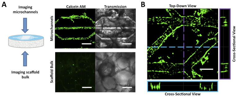
Representative CSLM fluorescence and transmission images of human microvascular endothelial cells (hMVECs) cultured in open microchannel platforms for seven days. hMVECs were stained with calcein AM to determine cell localization and viability within the michrochannels. (A) hMVECs proliferated to confluence in the microchannels but were sparsely observed in the scaffold bulk. Scale bars = 300 μm. (B) CSLM images of top-down and cross-sectional views showed that the hMVECs proliferated on the bottom and side walls of the channels. Scale bars = 300 μm.
While lumen formation in unenclosed channel platforms may be useful for studying fundamental mechanisms of endothelial lumen formation, from a tissue engineering standpoint, it is important that hMVECs undergo capillary morphogenesis in an enclosed configuration that supports tissue formation in three dimensions surrounding the microchannels. hMVECs were cultured in the enclosed silk system and assessed for the formation of lumen-like structures within the microchannels. Cells were seeded onto the unenclosed microchannels, cultured for two days and then enclosed using the fibrin adhesive (Figure 5A). Under static culture no lumen-like structures were observed in the microchannels over time. We attribute this outcome to the lack of nutrient delivery to the cells and a lack of mechanical stimulation from shear stresses resulting from fluid flow. Previous literature has shown that lumen formation is improved under shear conditions [32, 33] so the system was subsequently cultured in spinner flasks. Under dynamic conditions in spinner flasks, tissue sections stained with H&E showed lumen-like structures in the microchannels after one day of culture (Figure 5B). The lumen structures were maintained for at least seven days, but at day 14 no lumen structures were observed, likely due to incomplete vascular niche formation. It has been shown that capillary morphogenesis is susceptible to degradation when perivascular support is absent.[34] The lumen-like structures stained positive for the VE-cadherin, an endothelial marker for cell-cell junctions, further implicating these structures as precursors of capillary tubules (Figure 5C). It was found that hMVECs formed lumen-like structures in channel widths between 25 μm up to 300 μm. The channel width influenced the size of the lumen diameter (Figure 5D). This observation was corroborated by a similar observation in a collagen gel platform in which the channel size affected lumen diameter.[35] By providing a range of channel sizes the formation of lumen-like structures could be demonstrated for various branching levels of the vascular network.
Figure 5.

Representative histological cross-sections of hMVECs cultured in enclosed microchannel platforms. (A) Schematic of seeding and culturing procedure. hMVECS were cultured in an open channel platform for two days before enclosing the channels with fibrin adhesive. (B) H&E stained sections of enclosed channel platforms. Platforms were cultured either statically or dynamically in a spinner flask. Cells were sparsely observed in the microchannels of statically cultured platforms. In contrast, lumen-like structures were found in the microchannels of dynamically cultured platforms, indicated by black arrows. Scale bars = 100 μm. (C) Histological sections of platforms cultured in spinner flasks and probed for VE-cadherin. Intact lumen structures were observed at day one and four time points. At day seven, lumen-like structures appeared less intact. Scale bars = 100 um. (D) At day four, lumen-like structures were observed in 50 μm, 100 μm, and 200 μm wide channels. Lumen structures were not found in 25 μm wide channels. Scale bars = 50 um.
Co-culture studies were performed with hMVECs and hMSCs. The hMVECs were seeded in the microchannel space while the hMSCs were seeded in the bulk space (Figure 6A). Tissue sections after one day of dynamic culture in spinner flasks showed that the hMVECs localized to the microchannels while the hMSCs attached throughout the porous bulk surrounding the microchannels (Figure 6B). After seven days of dynamic culture the hMSCs remained localized in the bulk and were observed surrounding the microchannels (Figure 6B & 6C). This observation supports the hypothesis that a silk platform has potential to form complex tissues that contain a vascular niche. The vascular niche is composed of a luminal space lined with a single layer of endothelial cells that are anchored to a basement membrane. Surrounding the basement membrane are perivascular cells, which include pericytes and smooth muscle cells [36] that play a significant role in supporting capillary formation, maturation, and function.[34, 37] The perivascular cells can make direct cell-cell contact with the endothelium through the basement membrane [38, 39], which has been shown to mediate capillary vessel function.[34, 40] Previous research showed that hMSCs mimic the role of perivascular cells evidenced by forming perivascular unions in vitro with capillary networks [41] and prolonging endothelial lumen stability.[42] Therefore a porous microchannel wall is an important design criteria of a perfusion platform to allow the endothelial cells in the channel space to make direct contact with support cells cultured in the bulk space. Moreover, the silk micropatterened system enables controlled patterning of the vascular niche. Currently, randomly dispersed capillary network formation is achieved in tissue constructs by co-culturing endothelial and perivascular cells in fibrin hydrogels.[41, 43] However, tissues throughout the body have varying vascular branching hierarchies and vessel densities depending on the cellular oxygen/nutrient delivery and waste removal needs.[38] The silk micropatterened system presented here allows the microvascular bed to be tailored to the desired tissue being generated, which is a critical step towards developing functional engineered tissues.
Figure 6.

hMVECs co-cultured with human mesenchymal stem cells (hMSCs) in the microchannel platform. (A) Schematic of the seeding protocol. hMVECS were seeded first on the patterned scaffold surface. After two days of static culture, the microchannels were enclosed and hMSCs were seeded in the platform bulk space. (B) After the bonding step and one day of dynamic culture, the hMVECs (red) were observed in the microchannel space and the hMSCs (blue) were observed in the bulk space. After seven days of dynamic culture the hMVECs proliferated in the microchannel space, while hMSCs proliferated in the platform bulk (scale bars = 300 μm). (C) Higher magnification of a microchannel after seven days of dynamic culture shows hMVECs lining the microchannel while hMSCs populate the space around the microchannel (scale bar = 50 μm).
In addition to providing support to developing microvascular networks, the use of hMSCs in these scaffolds demsonstrates that this silk system could support a variety of tissues. Previously it has been shown that hMSCs differentiated down osteogenic and adipogenic lineages and that their differentiated state was maintained when co-cultured with endothelial cells.[44] In the present study, cell culture experiments showed that the microchannel pore sizes were sufficient for supporting a confluent layer of endothelial cells and for co-culturing two different cell types in distinct locations within the platform. Distinct localization of the vascular- and the tissue-forming space is important for developing physiologically relevant engineered constructs. Previous attempts to show that porous, micropatterened platforms improved nutrient delivery to large tissues demonstrated tissue formation within the channels and not in the bulk space between channels.[9, 11, 13] In order to recapitulate the complex nature of large tissues, endothelial regulation of nutrient delivery across the microchannel wall into the bulk space is necessary.
In contrast to previously reported microchannel systems fabricated from synthetic materials, the biomaterials platform reported here is capable of supporting cells in channels as well as in the bulk space. Synthetic systems lack appropriate porous bulk and cell compatible assembly, and therefore cannot support tissue formation in the bulk space around microchannels. Previously reported microchannel systems fabricated from biologic materials such as collagen, fibrin, and alginate have successfully supported cell growth in the platform bulk space. However, these biologic materials lack mechanical robustness and degrade quickly upon implantation. The silk-based perfusion system reported here is based on scaffolds that have mechanical strength that augments tissue repair and that have long, tunable degradation profiles in vivo [22, 45] all achieved without the need for chemical crosslinking. Additionally, the silk-based biomaterials platform reported here has a long shelf life; the platform can be assembled, autoclaved for sterility, and stored for extended time frames before being seeded with cells at a later time. In contrast, the biologic hydrogel systems fabricated from collagen, fibrin, and alginate must incorporate the parenchymal cell type during the microchannel fabrication step, which must be performed in a sterile environment.
The results from this study produced a unique system for engineering larger sized tissues and future work with this system will further inform the utility of this system for the field of regenerative medicine as well as for in vitro tissue systems for sustained cultivation. Successful development of this platform should enable systematic construction of larger, complex tissues for whole organ replacement.
4. Conclusions
A new silk-based biomaterial scaffold platform that contains porous microchannels and a porous bulk space is demonstrated. The microchannels can be fabricated with rectangular or half-moon profiles, and a wide range of channel widths and heights can be achieved to mimic various levels of capillary branching. This platform supports microvascular endothelial cell proliferation and lumen formation within the microchannels, which is an important niche to recapitulate in tissues that are developed in vitro. The microchannels can be fully enclosed to establish two distinct spaces for cell seeding and proliferation; the microchannel space and the bulk space. Mesenchymal stem cells were successfully co-cultured in the platform in the bulk space, which demonstrates the utility of this platform in supporting tissue formation in coordination with development of a microvascular system.
5. Experimental
Silk Solution Preparation
Silk fibroin was extracted from Bombyx mori silk worm cocoons according to previously published methods [46]. Cocoons were removed of the insect and immersed into boiling Na2CO3 solution (0.02 M, 5 g of cocoons:1 L of solution) for 30 minutes. The degummed fibers were rinsed with distilled water to remove residual Na2CO3 solution and air dried overnight. The dried fibers were solubilized in LiBr (9.3 M, 1 gram of dried fibers:4 mL of LiBr solution) at 60°C for four hours. Fifteen milliliters of the solubilized silk solution was dialyzed against distilled water (1 L) with a regenerated cellulose membrane (3,500 molecular weight cut off, Slide-A-Lyzer, Pierce, Rockford, IL). The water was changed after 1, 3, 6, 24, 36, and 48 hours at which point the LiBr was fully removed (determined by the conductivity of the dialysis water being less than 5 μS cm−1). The solubilized silk fibroin protein solution was removed from the dialysis cassettes and centrifuged to remove insoluble particulates and stored at 4°C. Protein concentration was determined by air drying a known volume of the silk solution and massing the remaining solids.
Photolithography and Mold Fabrication
Microfluidic channel patterns were designed using Layout Editor (Juspertor UG) and printed onto mylar masks using services from Advanced Reproductions (North Andover, MA). For channels with rectangular profiles, the mask pattern was transferred via photolithography to a 100 mm silicon wafer coated with SU-8 photoresist (25–150 μm thick) (Microchem, Newton, MA). For channels with semi-circular profiles, the mask pattern was transferred via photolithography to a 100 mm silicon wafer with a 500 μm-thick silicon nitride layer and coated with SPR220 photoresist (Dow Corning, Midland, MI). The patterned photoresist masked the silicon nitride layer during reactive ion etching (CF4: 100%, O2: 1%, base pressure: 65 mTorr, power: 25 W, etch time: 300 seconds). The wafer was then exposed to an isotropic HF/Nitric Acid/Acetic Acid (HNA) wet etch for 15 minutes. Polydimethylsiloxane (PDMS) (Dow Corning) was prepared by mixing the base reagent with the curing reagent in a 10:1 mass ratio and cast onto the photoresist. The PDMS was cured at 60°C for four hours and then delaminated from the photoresist. The PDMS mold was trimmed to fit the bottom of a 1.5 cm diameter cylindrical container for scaffold assembly.
Scaffold Assembly and Analysis
A solution of silk (1% w v−1) and polyethylene oxide (PEO) (0.035% w v−1) (Sigma-Aldrich, St. Louis, MO) was dispensed (74 μL of solution per 1 cm2 PDMS mold surface area) on to the PDMS mold and dried overnight at room temperature according to a previously published method [47]. For non-patterned scaffolds, the solution was dispensed on a flat PDMS mold. While on the PDMS mold, the dried film was water-annealed for 12 hours to induce β-sheet formation and placed into a 1.5 cm diameter cylindrical container. A silk solution (6% w v−1, 500 μL) was poured over the mold and granular NaCl (1 g, Ø = 500–600 μm) (Sigma-Aldrich) was sifted into the silk solution. The silk was cured for 48 hours, after which the plates were immersed in distilled water (4 L) for 48 hours (water was changed twice) to leach out the polyethylene oxide and NaCl. The remaining silk scaffold was detached and the thickness was trimmed to 500 μm using a scaffold trimming device designed in the lab. Scaffolds were stored at 4°C in distilled water. Tensile mechanical properties of hydrated samples (Ø=15 mm, height=5 mm) were obtained using an Instron 3366 (Norwood, MA) testing frame equipped with a 10 N load cell. The tests were carried out in phosphate buffered saline (0.1 M) (Invitrogen, Carlsbad, CA) at 37°C at a strain rate of 5 mm min−1. The sample modulus and yield strength were determined from the stress-strain curve normalized to the cross-sectional area of the scaffold using a Labview program written in-house as previously described [48]. Briefly, the tensile modulus was defined as the slope of the linear region between 10% and 25% strain. Tensile yield strength was defined as the stress at the intersection of the stress-strain curve and a line parallel to the linear region, offset by 0.5% strain. Silk scaffold microchannel morphology was characterized with scanning electron microscopy (SEM). To image the platform porous bulk space and microchannel cross-sections, samples were sliced with a stainless steel scalpel blade. In order to maintain silk structure in a dry state, samples were frozen at −80°C for >4 hours and lyophilized for 12 hours. Samples were sputter coated with Pt/Pd (60 seconds, 40 mA) and imaged with a Supra55VP field emission SEM (Zeiss, Oberkochen, Germany).
Scaffold Bonding
To bond the microfluidic channels, two adhesives were investigated: fibrin and a silk-based pH gel. Fibrin adhesive was prepared by mixing fibrinogen (10 mg mL−1) (EMD Biosciences, Darmstadt, Germany) with thrombin (5 units mL−1) (Sigma-Aldrich) in a 4:1 volume ratio. pH gelation (pH-gel) was performed according to previously reported methods [49]. Briefly, HCl (0.3 M) was mixed with silk (6% w v−1) in a 1:9 volume ratio. The adhesive solution was evenly pipetted onto the flat sponge (56 μL per cm2 of scaffold bonding surface area), which was then placed on top of the micropatterned sponge and cured either at 37°C for the fibrin adhesive or room temperature for the pH gel.
Cell Culture
Scaffolds were sterilized in 70% ethanol overnight. Prior to cell seeding, scaffolds were rinsed three times with phosphate buffer saline (Invitrogen). To promote cell attachment, scaffolds were coated in human derived fibronectin (200 μL, 10 μg mL−1) (Sigma-Aldrich). Human dermal microvascular endothelial cells (hMVECs) (P5–P8, Lonza, Basel, Switzerland) in Microvascular Endothelial Cell Growth Medium-2 (Lonza) and 5% fetal bovine serum (FBS) (Lonza) were initially seeded at a density of 800,000 cells per scaffold (diameter=15 mm; height=500 μm) and incubated at 5% CO2 and 37°C. Media was exchanged every 2–3 days. To visualize hMVEC proliferation in the open microfluidic channels, hMVECs were incubated with calcein AM (2 μM) (Invitrogen) for 45 minutes and imaged with confocal laser microscopy (ex: 488 nm; em: 510–520 nm) (Leica, Wetzlar, Germany). hMVECs were cultured in enclosed microchannels by first seeding cells on open channel scaffolds (800,000 cells per scaffold) and allowed to attach and proliferate for two days. Scaffolds were enclosed by dispensing fibrin adhesive (100 μL) to a flat surface scaffold and stacking on top of a patterned surface scaffold. The adhesive was cured for 30 minutes at at 5% CO2 and 37°C after which the constructs were cultured either statically in tissue culture plates or spinner flasks with a stir bar rotating at 60 rotations per minute. For co-culture studies hMVECs were incubated in DiI (5 ng mL−1) (Invitrogen) for 45 minutes before being seeded. hMSCs (P1–P5, Lonza) were cultured in Dulbecco’s modified eagle serum with 5% FBS and 1% antibiotic/antimycotic (Invitrogen). For co-culture studies hMSCs were incubated in DiD (5 ng mL−1) (Invitrogen) for 45 minutes before being seeded.
Immunohistochemistry (IHC)
Samples were fixed with 10% neutral buffered formalin (NBF) for 24 hours and embedded in paraffin after a series of xylene and graded ethanol washes. Samples were sectioned (6–9 μm thickness), deparaffinized and stained with hematoxylin and eosin (H&E) (Sigma-Aldrich) to visualize cell nuclei and cytoplasm, respectively. In order to characterize lumen formation, sections were probed with primary antibodies against the endothelial cell marker, VE-cadherin (1:200 dilution, Santa Cruz Biotechnology, Santa Cruz, CA). The primary antibodies were probed with biotinylated secondary antibodies, developed with peroxidase, and counterstained with hematoxylin using reagents from a Histostain-SP kit (Invitrogen). For co-culture studies, samples were fixed in 10% NBF for 24 hours and soaked in 30% sucrose for 12 hours. Samples were embedded in Tissue-Tek O.C.T. freezing medium (EMS, Hatfield, PA), sectioned (6–15 μm thickness), and imaged with a fluorescent microscope (Leica).
Acknowledgments
We thank the National Institutes of Health (EB002520, AR061988), National Science Foundation Graduate Research Fellowship Program (NSF DGE 0806676), and the AFOSR for support of this research.
References
- 1.Laschke MW, Harder Y, Amon M, Martin I, Farhadi J, Ring A, Torio-Padron N, Schramm R, Rucker M, Junker D. Tissue Eng. 2006;12(8):2093–2104. doi: 10.1089/ten.2006.12.2093. [DOI] [PubMed] [Google Scholar]
- 2.Lokmic Z, Mitchell GM. Tissue Eng, Part B. 2008;14(1):87–103. doi: 10.1089/teb.2007.0299. [DOI] [PubMed] [Google Scholar]
- 3.Rouwkema J, Rivron NC, van Blitterswijk CA. Trends Biotechnol. 2008;26(8):434–441. doi: 10.1016/j.tibtech.2008.04.009. [DOI] [PubMed] [Google Scholar]
- 4.Moore DH, Ruska H. J Biophys Biochem Cytol. 1957;3(3):457–462. doi: 10.1083/jcb.3.3.457. [DOI] [PMC free article] [PubMed] [Google Scholar]
- 5.Clough G. Prog Biophys Mol Biol. 1991;55(1):47–69. doi: 10.1016/0079-6107(91)90011-g. [DOI] [PubMed] [Google Scholar]
- 6.King KR, Wang CCJ, Kaazempur-Mofrad MR, Vacanti JP, Borenstein JT. Adv Mater. 2004;16(22):2007–2012. [Google Scholar]
- 7.Fidkowski C, Kaazempur-Mofrad MR, Borenstein J, Vacanti JP, Langer R, Wang Y. Tissue Eng. 2005;11(1–2):302–309. doi: 10.1089/ten.2005.11.302. [DOI] [PubMed] [Google Scholar]
- 8.Wang GJ, Chen CL, Hsu SH, Chiang YL. Microsyst Technol. 2005;12(1):120–127. [Google Scholar]
- 9.Sarkar S, Lee GY, Wong JY, Desai TA. Biomaterials. 2006;27(27):4775–4782. doi: 10.1016/j.biomaterials.2006.04.038. [DOI] [PubMed] [Google Scholar]
- 10.Borenstein JT, Tupper MM, Mack PJ, Weinberg EJ, Khalil AS, Hsiao J, García-Cardeña G. Biomed Microdevices. 2010;12(1):71–79. doi: 10.1007/s10544-009-9361-1. [DOI] [PubMed] [Google Scholar]
- 11.Kennedy J, McCandless S, Rauf A, Williams L, Hillam J, Hitchcock R. Acta Biomater. 2011;7(11):3896–3904. doi: 10.1016/j.actbio.2011.06.037. [DOI] [PubMed] [Google Scholar]
- 12.Sung HJ, Meredith C, Johnson C, Galis ZS. Biomaterials. 2004;25(26):5735–5742. doi: 10.1016/j.biomaterials.2004.01.066. [DOI] [PubMed] [Google Scholar]
- 13.Lee CH, Lim YC, Farson DF, Powell HM, Lannutti JJ. Ann Biomed Eng. 2011;39(12):3031–3041. doi: 10.1007/s10439-011-0417-z. [DOI] [PubMed] [Google Scholar]
- 14.Chrobak KM, Potter DR, Tien J. Microvasc Res. 2006;71(3):185–196. doi: 10.1016/j.mvr.2006.02.005. [DOI] [PubMed] [Google Scholar]
- 15.Golden AP, Tien J. Lab Chip. 2007;7(6):720–725. doi: 10.1039/b618409j. [DOI] [PubMed] [Google Scholar]
- 16.Choi NW, Cabodi M, Held B, Gleghorn JP, Bonassar LJ, Stroock AD. Nat Mater. 2007;6:908–915. doi: 10.1038/nmat2022. [DOI] [PubMed] [Google Scholar]
- 17.Willoughby CE, Batterbury M, Kaye SB. Surv Ophthalmol. 2002;47(2):174–182. doi: 10.1016/s0039-6257(01)00304-6. [DOI] [PubMed] [Google Scholar]
- 18.Fussenegger M, Meinhart J, Höbling W, Kullich W, Funk S, Bernatzky G. Ann Plast Surg. 2003;51(5):493. doi: 10.1097/01.sap.0000067726.32731.E1. [DOI] [PubMed] [Google Scholar]
- 19.Eyrich D, Brandl F, Appel B, Wiese H, Maier G, Wenzel M, Staudenmaier R, Goepferich A, Blunk T. Biomaterials. 2007;28(1):55–65. doi: 10.1016/j.biomaterials.2006.08.027. [DOI] [PubMed] [Google Scholar]
- 20.Mauney JR, Nguyen T, Gillen K, Kirker-Head C, Gimble JM, Kaplan DL. Biomaterials. 2007;28(35):5280–5290. doi: 10.1016/j.biomaterials.2007.08.017. [DOI] [PMC free article] [PubMed] [Google Scholar]
- 21.Hutmacher DW. J Biomater Sci, Polym Ed. 2001;12(1):107–124. doi: 10.1163/156856201744489. [DOI] [PubMed] [Google Scholar]
- 22.Wang Y, Rudym DD, Walsh A, Abrahamsen L, Kim HJ, Kim HS, Kirker-Head C, Kaplan DL. Biomaterials. 2008;29(24–25):3415–3428. doi: 10.1016/j.biomaterials.2008.05.002. [DOI] [PMC free article] [PubMed] [Google Scholar]
- 23.Bettinger C, Cyr K, Matsumoto A, Langer R, Borenstein J, Kaplan D. Adv Mater. 2007;19(19):2847–2847. doi: 10.1002/adma.200602487. [DOI] [PMC free article] [PubMed] [Google Scholar]
- 24.Borenstein JT, Megley K, Wall K, Pritchard EM, Truong D, Kaplan DL, Tao SL, Herman IM. Materials. 2010;3(3):1833–1844. [Google Scholar]
- 25.Sherman T. J Gen Physiol. 1981;78(4):431–453. doi: 10.1085/jgp.78.4.431. [DOI] [PMC free article] [PubMed] [Google Scholar]
- 26.Pries AR, Secomb TW, Gaehtgens P. Circ Res. 1995;77(5):1017–1023. doi: 10.1161/01.res.77.5.1017. [DOI] [PubMed] [Google Scholar]
- 27.Plyley MJ, Sutherland GJ, Groom AC. Microvasc Res. 1976;11(2):161–173. doi: 10.1016/0026-2862(76)90048-0. [DOI] [PubMed] [Google Scholar]
- 28.Imayama S. J Invest Dermatol. 1981;76(3):151–157. doi: 10.1111/1523-1747.ep12525558. [DOI] [PubMed] [Google Scholar]
- 29.Marois Y. ASAIO J. 1999;45(4):272–280. [PubMed] [Google Scholar]
- 30.Salem A, Stevens R, Pearson R, Davies M, Tendler S, Roberts C, Williams P, Shakesheff K. J Biomed Mater Res. 2002;61(2):212–217. doi: 10.1002/jbm.10195. [DOI] [PubMed] [Google Scholar]
- 31.Koh W, Mahan RD, Davis GE. J Cell Sci. 2008;121(7):989–1001. doi: 10.1242/jcs.020693. [DOI] [PubMed] [Google Scholar]
- 32.Yamamoto K, Takahashi T, Asahara T, Ohura N, Sokabe T, Kamiya A, Ando J. J Appl Physiol. 2003;95(5):2081–2088. doi: 10.1152/japplphysiol.00232.2003. [DOI] [PubMed] [Google Scholar]
- 33.Ueda A, Koga M, Ikeda M, Kudo S, Tanishita K. Am J Physiol: Heart Circ Physiol. 2004;287(3):H994–H1002. doi: 10.1152/ajpheart.00400.2003. [DOI] [PubMed] [Google Scholar]
- 34.Hellström M, Gerhardt H, Kalén M, Li X, Eriksson U, Wolburg H, Betsholtz C. J Cell Biol. 2001;153(3):543–554. doi: 10.1083/jcb.153.3.543. [DOI] [PMC free article] [PubMed] [Google Scholar]
- 35.Raghavan S, Nelson CM, Baranski JD, Lim E, Chen CS. Tissue Eng, Part A. 2010;16(7):2255–2263. doi: 10.1089/ten.tea.2009.0584. [DOI] [PMC free article] [PubMed] [Google Scholar]
- 36.Nikolova G, Strilic B, Lammert E. Trends Cell Biol. 2007;17(1):19–25. doi: 10.1016/j.tcb.2006.11.005. [DOI] [PubMed] [Google Scholar]
- 37.Stratman AN, Malotte KM, Mahan RD, Davis MJ, Davis GE. Blood. 2009;114(24):5091–5101. doi: 10.1182/blood-2009-05-222364. [DOI] [PMC free article] [PubMed] [Google Scholar]
- 38.Simionescu M, Simionescu N, Palade GE. J Cell Biol. 1974;60(1):128–152. doi: 10.1083/jcb.60.1.128. [DOI] [PMC free article] [PubMed] [Google Scholar]
- 39.Armulik A, Abramsson A, Betsholtz C. Circ Res. 2005;97(6):512–523. doi: 10.1161/01.RES.0000182903.16652.d7. [DOI] [PubMed] [Google Scholar]
- 40.Gerhardt H, Betsholtz C. Cell Tissue Res. 2003;314(1):15–23. doi: 10.1007/s00441-003-0745-x. [DOI] [PubMed] [Google Scholar]
- 41.Carrion B, Huang CP, Ghajar CM, Kachgal S, Kniazeva E, Jeon NL, Putnam AJ. Biotechnol Bioeng. 107(6):1020–1028. doi: 10.1002/bit.22891. [DOI] [PMC free article] [PubMed] [Google Scholar]
- 42.Au P, Tam J, Fukumura D, Jain RK. Blood. 2008;111(9):4551–4558. doi: 10.1182/blood-2007-10-118273. [DOI] [PMC free article] [PubMed] [Google Scholar]
- 43.Trkov S, Eng G, Di Liddo R, Parnigotto PP, Vunjak-Novakovic G. J Tissue Eng Regener Med. 2010;4(3):205–215. doi: 10.1002/term.231. [DOI] [PMC free article] [PubMed] [Google Scholar]
- 44.Ern C, Krump-Konvalinkova V, Docheva D, Schindler S, Rossmann O, Böcker W, Mutschler W, Schieker M. Open Biomed Eng J. 2010;4:190–198. doi: 10.2174/1874120701004010190. [DOI] [PMC free article] [PubMed] [Google Scholar]
- 45.Horan RL, Antle K, Collette AL, Wang Y, Huang J, Moreau JE, Volloch V, Kaplan DL, Altman GH. Biomaterials. 2005;26(17):3385–3393. doi: 10.1016/j.biomaterials.2004.09.020. [DOI] [PubMed] [Google Scholar]
- 46.Rockwood DN, Preda RC, Yücel T, Wang X, Lovett ML, Kaplan DL. Nat Protoc. 2011;6(10):1612–1631. doi: 10.1038/nprot.2011.379. [DOI] [PMC free article] [PubMed] [Google Scholar]
- 47.Gil ES, Mandal BB, Park SH, Marchant JK, Omenetto FG, Kaplan DL. Biomaterials. 2010;31(34):8953–8963. doi: 10.1016/j.biomaterials.2010.08.017. [DOI] [PMC free article] [PubMed] [Google Scholar]
- 48.Gil ES, Kluge JA, Rockwood DN, Rajkhowa R, Wang L, Wang X, Kaplan DL. J Biomed Mater Res A. 2011;99(1):16–28. doi: 10.1002/jbm.a.33158. [DOI] [PMC free article] [PubMed] [Google Scholar]
- 49.Yucel T, Kojic N, Leisk GG, Lo TJ, Kaplan DL. J Struct Biol. 2010;170(2):406–412. doi: 10.1016/j.jsb.2009.12.012. [DOI] [PMC free article] [PubMed] [Google Scholar]