Abstract.
The mouse ischemic hindlimb model is used widely for studying collateral artery growth (i.e., arteriogenesis) in response to increased shear stress. Nonetheless, precise measurements of regional shear stress changes along individual collateral arteries are lacking. Our goal is to develop and verify trans-illumination laser speckle flowmetry (LSF) for this purpose. Studies of defibrinated bovine blood flow through tubes embedded in tissue-mimicking phantoms indicate that trans-illumination LSF better maintains sensitivity with an increasing tissue depth when compared to epi-illumination, with an reduction in the exponential decay of the speckle velocity signal. Applying trans-illuminated LSF to the gracilis muscle collateral artery network in vivo yields both improved sensitivity and reduced noise when compared to epi-illumination. Trans-illuminated LSF images reveal regional differences in collateral artery blood velocity after femoral artery ligation and are used to measure an -fold increase in the shear stress at the entrance regions to the muscle. We believe these represent the first direct measurements of regional shear stress changes in individual mouse collateral arteries. The ability to capture deeper vascular signals using a trans-illumination configuration for LSF may expand the current applications for LSF, which could have bearing on determining how shear stress magnitude and direction regulate arteriogenesis.
Keywords: arteriogenesis, shear stress, laser speckle imaging, mouse ischemic hindlimb
1. Introduction
The importance of adequate remodeling of pre-existing arterial interconnections to form endogenous collateral bypasses—i.e., arteriogenesis—is highlighted in the extensive link between adequate collateral development and enhanced patient outcomes with arterial occlusive disease.1,2 The key initiating stimulus for arteriogenesis is increased shear stress.3 Upon occlusion of a major artery, downstream pressure is reduced, causing an increase in the pressure gradient, blood flow, and shear stress along pre-existing collateral arteries that bypass the occlusion. Both the magnitude4 and duration5 of increased shear stress determine maximal collateral outgrowth and eventual resolution. Nonetheless, direct measurements of shear stress magnitude along individual collateral arteries have not been reported. We believe this paucity of hemodynamic information is due, at least in part, to the lack of a method capable of making such measurements. The primary challenges are the small caliber of the developing collateral vessels (often in an initial ) and the need to integrate these data over a large area. Of the technologies with sufficient spatial resolution, such as multiphoton excitation fluorescence,6,7 optical coherence tomography,8,9 and photoacoustic tomography,10,11 there are still multiple barriers to their adoption for studying arteriogenesis. These include cost and technical expertise, depth of imaging, and data integration over the observed vascular networks. One potential solution is laser speckle flowmetry (LSF) microscopy. Both relative flow and functional microvascular density have been measured by LSF in cerebral,12–15 retinal,13,16,17 and dorsal skinfold window chamber microcirculation. From a theoretical standpoint, absolute LSF measurements are possible,13 and we have recently shown LSF to be an efficient solution for measuring flow changes across large microvascular networks.18 The use of LSF has, however, been limited by the depth of signal acquisition to the most superficial vascular structures.19 In turn, this limits its application for analysis of collateral arteries embedded deeply in the tissue. To increase acquisition depth, a recent report20 suggested that the reorientation of the illumination source to transmission through the tissue could project and capture the hemodynamic signals from deeper vascular structures. Here, we developed a trans-illumination-based LSF system to measure, for the first time, the in vivo spatial distribution of collateral artery hemodynamics before and after femoral artery ligation (FAL) in the mouse ischemic hindlimb, which is the most widely used model of peripheral arteriogenesis.
2. Materials and Methods
2.1. LSF Setup and Data Analysis
When a coherent light source passes through a static tissue, it creates a random interference pattern known as speckle. The speckle pattern produced is characteristic for a given tissue structure. When particles move within the given tissue (i.e., red blood cells), it causes the speckle pattern to fluctuate, such that when these fluctuations are integrated over time it is possible to use spatial statistics to determine tissue motion.21 We have previously shown that, when using a simplified algorithm developed to remove the assumption of Gaussian or Lorentzian distributions,22 it is possible to find relative changes in blood flow in the microcirculation at an individual vessel level.18 The approach relates the change in speckle contrast [, Eq. (1)] to autocorrelation time [, Eq. (2)], which is inversely proportional to blood velocity [speckle intensity (SI), Eq. (2)]
| (1) |
| (2) |
Here, is derived on a per-pixel basis from the standard deviation [, Eq. (1)] and mean pixel intensity [, Eq. (1)] values in a neighborhood. The neighborhood size was chosen based on a balance between improved signal-to-noise ratio and decreased spatial resolution with an increasing window size. We have previously demonstrated this to be applicable for mouse arterioles of the diameter of gracilis collateral arteries.18 For our calculations, we used a simplified algorithm [Eq. (2)] for relating speckle contrast () and exposure time () to autocorrelation time [, Eq. (2)]. Vessel speckle velocity was normalized speckle index (NSI) to the background tissue according to Eq. (3). As previously described,18 this process removes background artifact from general tissue motion and variations in speckle illumination to allow for comparison of velocity change across experiments
| (3) |
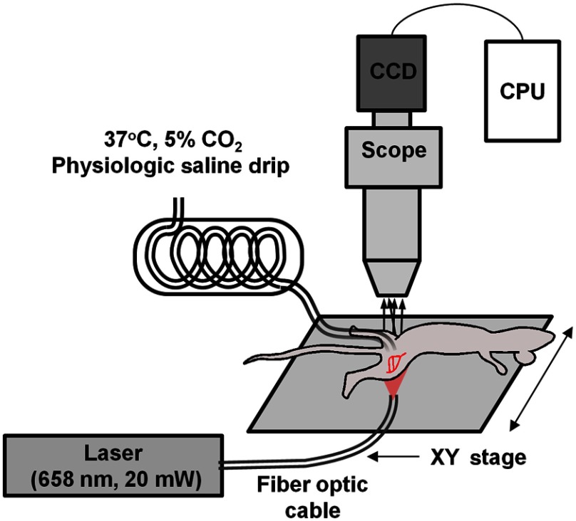
In our arrangement, a 30-mW, 658-nm laser diode (LPM658-30, Newport Corporation, Irvine, CA) was coupled to a fiber optic cable and used to illuminate the tissue or tissue phantom from either an epi-illumination or trans-illumination orientation, where the fiber output was placed at the base of the (phantom) tissue. An illustration of the laser speckle imaging system, as applied to the mouse gracilis adductor collateral arteries in the trans-illumination orientation, is shown in Fig. 1. For both in vitro and in vivo testing, a cooled, monochrome charge-coupled device camera (Optronics Quantifier, Goleta, CA) () was used to acquire the raw speckle images through an intravital microscope (Zeiss Axioskop, Thornwood, NY) using a air objective (Zeiss Acroplan LD ). As previously described,18 the objective and camera were chosen to balance the resolution of the scope with the size of the speckle to satisfy the Nyquist sampling criteria of at least 2 pixels per individual speckle.23
Fig. 1.
In vivo intravital imaging of collateral artery hemodynamics. The fiber optic cable was positioned for either trans-illumination or epi-illumination. For the trans-illumination configuration, the fiber optic outlet was placed on the opposite side of the leg from the exposed muscle and against the depilated skin to yield an evenly illuminated field of view. For the epi-illumination configuration, the fiber optic outlet was positioned to produce an unobstructed and even sheet of light on the surface of the exposed muscle. The given field of view was shifted using an -stage.
For each field of view, laser position, and flow setting, a sequence of 12-bit raw speckle images was acquired with 5-ms exposure time to capture average velocity over multiple cardiac cycles. Camera gain and light path intensity were varied to maintain mean pixel intensity of the raw speckle image. To minimize the influence of whole background tissue motion from mouse movement, the processed SI images were normalized to median background intensity. Code for converting raw speckle images into speckle flow maps was developed, implemented, and analyzed in Fiji,24 and is freely available upon request. Individual flow images were then merged into larger two-dimensional maps using Adobe Photoshop (CS2, Adobe Systems Inc., San Jose, CA).
2.2. Tissue Phantom Studies
While initial studies suggested that speckle signal analysis from transmitted laser light yields dominant vascular signals from deeper tissue structures20 and that speckle signals remain viable through up to 2 cm of biological tissue,25 the applicability of signal processing used for epi-illumination versus trans-illumination was unknown. Therefore, light scattering tissue phantoms were used to test speckle velocity linearity between trans-illumination and epi-illumination speckle arrangements. Phantoms were generated as previously described18 by adding titanium dioxide nanopowder (677469, Sigma-Aldrich, St. Louis, MO) to 184 Sylgard PDMS gel (Dow Corning, Midland, MI) at and pouring the mixture over optical glass-bottomed molds. Phantoms were then allowed to cure overnight at 37°C. Molds 5-mm thick were composed of polyethylene tubing connected to glass capillary tubes with 142-μm inner diameter (Drummond Microcap, P1799 Sigma-Aldrich, St. Louis, MO) placed at 0, 120, 360, and 720 μm from the surface. These values were chosen to approximately represent the range of depths at which the collateral arteries reside under the top surface of the mouse gracilis muscle, which has a thickness of .
For validating the linear operation of the speckle processing algorithm for both epi-illumination and trans-illumination arrangements, a sequence of known flows of defibrinated bovine blood (Hemostat Labs, Dixon, CA) was driven via a syringe pump (PHD2000, Harvard Apparatus, Holliston, MA) through the phantom. The randomized sequence and image acquisition were controlled by a custom-designed LabVIEW program (National Instruments, Austin, TX). Only data from the most superficial capillary tube was analyzed. Each complete program of flow rates was repeated five times (i.e., ) for both epi-illumination and trans-illumination configurations.
For testing the effect of increasing depth on speckle signal attenuation, a single flow rate was applied to the phantom, and raw speckle images were captured at each capillary tube depth (0, 120, 360, and 720 μm). The image capture sequence at each depth setting was repeated five times for both epi-illumination and trans-illumination configurations.
2.3. In Vivo Analysis of Deep Collateral Blood Flow in Trans-illuminated Mouse Hindlimb
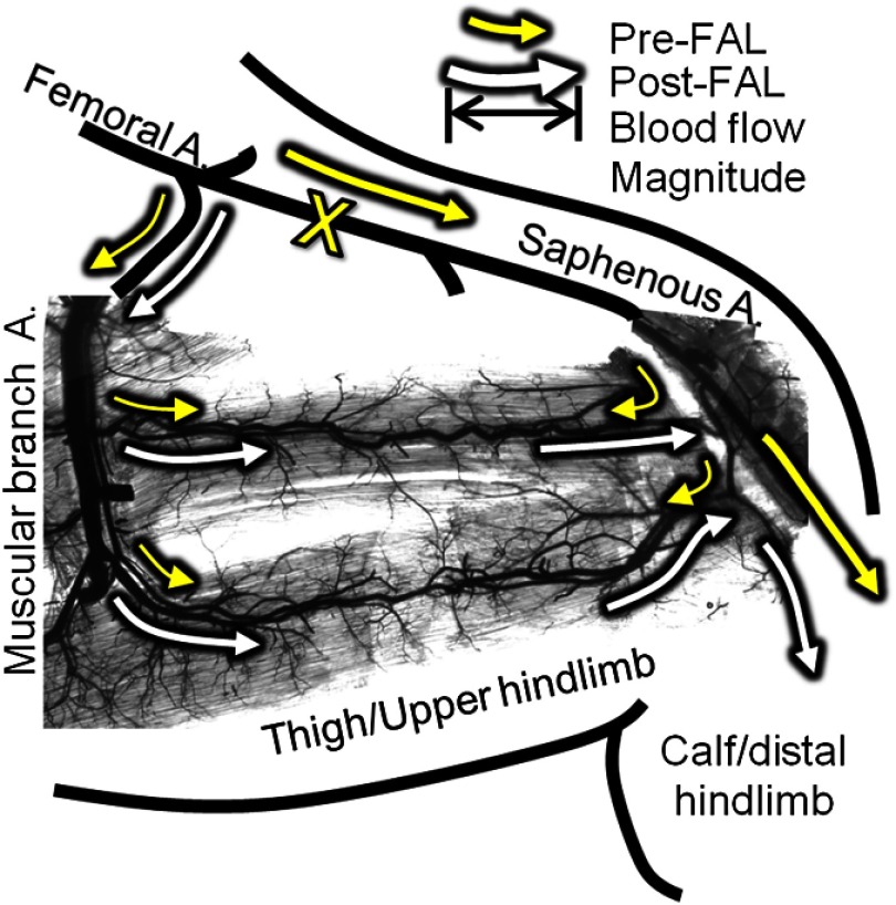
All animal protocols were approved by the Institutional Animal Care and Use Committee at the University of Virginia and conformed to all regulations for animal use outlined in the American Heart Association Guidelines for the Use of Animals in Research. Male C57BL/6 mice () were purchased from Charles River Laboratory (Wilmington, MA) and housed in the animal facilities at the University of Virginia. To produce consistent flow increases in the collateral arteries in a superficial adductor muscle, the FAL scheme in Fig. 2 was chosen. This particular ligation pattern has been previously shown to produce consistent arteriogenesis in the collateral arteries of the gracilis adductor muscles26–29 with minimal heterogeneity in the baseline collateral structure and with the predicted changes in flow direction from baseline. Mice, 9 to 13 weeks of age, were anesthetized (i.p. ketamine, xylazine, and atropine), depilated, and prepped for aseptic surgery. On the left leg, an incision was made directly above and along the femoral artery, and a window of skin was dissected free and retracted directly above the superficial adductor muscles. The femoral artery was gently dissected from the femoral vein and nerve between the bifurcation of the superior epigastric artery and popliteal artery. Two 6.0 silk sutures were placed underneath the femoral artery, but not yet tied, immediately distal to the epigastric artery, which served as the origin of the muscular branch artery in all mice.
Fig. 2.
Schematic of the primary gracilis adductor collateral pathways superimposed upon an image of a vascular cast of the gracilis muscle. Arrows indicate the predicted direction and magnitude of blood flow both pre- (yellow) and post- (white) femoral artery ligation (FAL) (denoted by “X”). Flow direction reverses from pre- to post-FAL in the collateral entry region nearest the saphenous artery (i.e., right side), but does not in the muscular branch entrance region (i.e., left side).
Upon placement of the ligature (untied), the mouse was transferred to the intravital microscopy station, and the exposed tissue was maintained under a constant drip of warmed Ringer’s solution ( NaCl, KCl, , , ) that was prepared with 5% balance , and set to maintain 37°C fluid temperature. Mouse body temperature was maintained by a surgical heating pad. For imaging of gracilis collateral hemodynamics, we used the intravital microscopy setup shown in Fig. 2. Before baseline imaging, muscles were allowed 15 min to equilibrate while being superfused with warmed Ringer’s solution. After the equilibration period, a baseline (preligation) series of image acquisitions using epi-illumination and then trans-illumination laser orientation were taken at multiple fields of view to encompass the gracilis collateral arteries between the saphenous and the muscular branch arteries. Between each series of raw speckle images (epi- and trans-illumination), images of the collateral arteries were taken using brightfield epi-illumination through an objective-mounted fiber optic light guide to allow for lumenal diameter measurements (A08650, Schott Inc., Elmsford, NY). After baseline acquisition, the ligature was tightened, and stoppage of blood flow through the femoral artery was visually confirmed in all mice. After 30 min post-ligation, trans-illumination speckle and brightfield then epi-illumination and brightfield imaging sequences were repeated. Predicted baseline and post-ligation flow direction were confirmed in an identical preparation on a separate set of mice through fluorescent imaging of intravascularly injected fluorescent microspheres (FP-3070-2, Spherotech Inc., Forest Lake, IL).
Blood velocity analysis of laser speckle images was limited to well-defined collateral artery regions, such that bulk microvascular flow in the surrounding gracilis muscle flow was not considered. The assumption of Poiseuille flow was made, where wall shear rate is proportional to average blood velocity divided by tube diameter. This assumption is valid for most cases in the microcirculation.30 Therefore, proportional wall shear rate [speckle shear stress (SSR)] was calculated using the NSI measurement of average blood velocity and vessel diameter () at each designated location [Eq. (4)]
| (4) |
3. Results
3.1. Influence of Illumination Source on Sensitivity as a Function of Depth in Tissue Phantoms
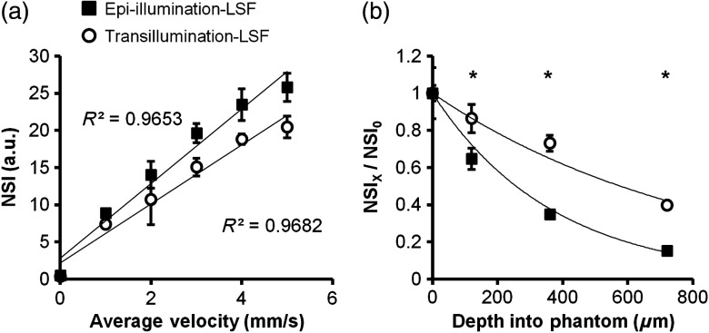
The results from the tissue phantom experiments are shown in Fig. 3. Both trans- and epi-illumination exhibited a strong linear relationship between NSI and absolute velocity [Fig. 3(a)]. However, the trans-illumination signal was not as significantly diminished with an increasing tissue depth, showing an reduction of the exponential decay of the speckle velocity signal with an increasing depth compared to epi-illumination [ versus , Fig. 3(b) at a constant velocity of ]. As such, trans-illumination maintained 40% of the initial superficial signal out to 720-μm deep within the tissue phantom versus 15% with epi-illumination.
Fig. 3.
Trans-illumination maintains linear relationship between normalized speckle index (NSI) and increases sensitivity to deeper velocity signals in vitro. (a) Line graph of NSI for both epi-illumination (closed squares) and trans-illumination (open circles) configurations ( independent trials) as a function of known blood velocity. Both configurations demonstrated similar and highly linear relationships. (b) Graph of speckle velocity (), normalized to surface speckle velocity (), as a function of depth for epi-illumination and trans-illumination and fitted with an exponential relationship (line). * between epi- and trans-illumination at the same depth.
3.2. Trans-illumination LSF Microscopy Better Demonstrates Regional Variation of Hemodynamic Changes Along Collateral Arteries After FAL
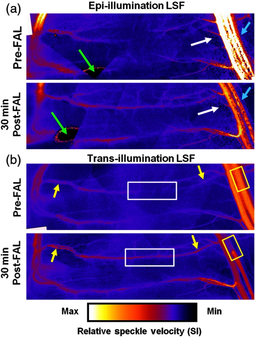
A representative comparison of in vivo images created by epi-illumination and trans-illumination LSF is shown in Fig. 4. While epi-illumination LSF [Fig. 4(a)] was somewhat capable of visualizing the most superficial elements of the gracilis collateral network (e.g., the saphenous artery and upstream region of the muscular branch), it generally yielded much poorer quality images. Epi-illumination LSF images exhibited significantly more noise when compared to the trans-illumination images [Fig. 4(b)], with much of this noise being generated by superficial fat cells overlying the muscle [Fig. 4(a), white arrows), especially in the collateral entry region near the saphenous artery. Epi-illumination images were also susceptible to errors created by light being directly reflected off the tissue surface [Fig. 4(a), green arrows]. As seen in Fig. 4(b), these noise and error issues were entirely obviated by switching to trans-illumination.
Fig. 4.
Comparison of LSF blood flow maps generated with epi- and trans-illumination. The change from low flow at the entrance regions with a point of convergence in the central regions pre-FAL to high flow continuously across the collateral arteries was apparent in all experiments (). White box: markedly enhanced flow in the central collateral region. Yellow boxes: decreased post-FAL saphenous artery flow. Yellow arrows: enhanced flow in collateral entrance regions evident with trans-illumination. White arrows: noise comparison between epi- and trans-illumination. Cyan arrows: diminished post-FAL saphenous artery flow signal is cleaner with trans-illumination LSF.
Post-FAL, as expected, both the central [Fig. 4(b), white boxes] and entrance regions [Fig. 4(b), yellow arrows] of the gracilis collateral network experienced significant increases in the blood flow that were clearly evident with trans-illumination. Epi-illumination imaging was capable of capturing some of the characteristics of increased flow, but sensitivity within the collateral network was considerably poorer. The FAL also induced an expected drop in saphenous artery flow [Fig. 4(b), yellow boxes], which was evident with both epi- and trans-illumination. However, the pre-FAL epi-illumination signal was often saturated, and both the pre- and post-FAL saphenous flow signals were prone to considerable noise [Fig. 4(a), cyan arrows]. Finally, it is important to note that, while trans-illumination yielded better image quality, further improvements in spatial resolution could be realized by incorporating more sophisticated temporal laser speckle contrast analyses.31,32 Limitations on camera control and frame rate precluded such analyses in the current study.
3.3. Velocity and Shear Rate Changes Generated by FAL
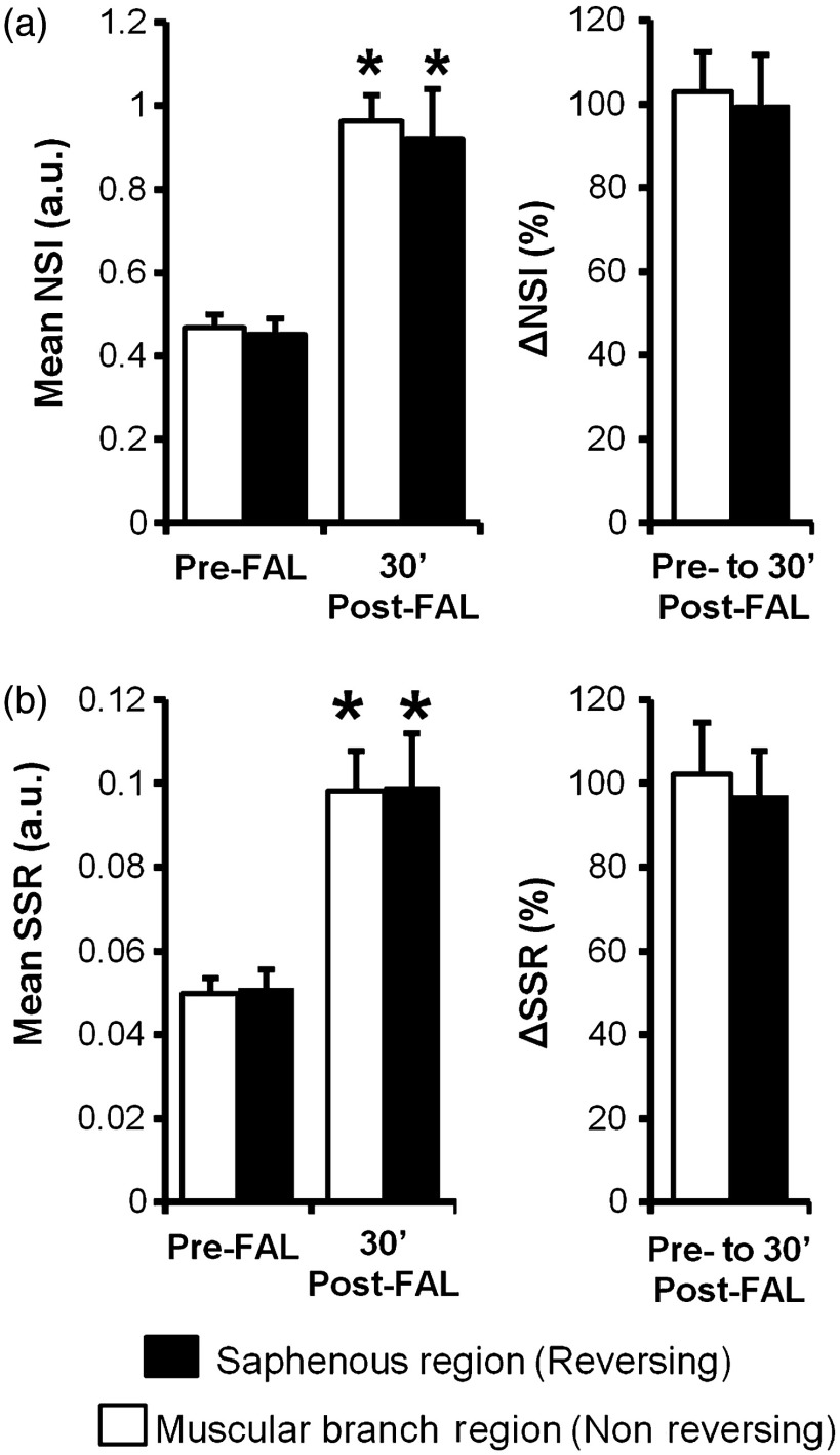
Because there were no changes in depth of the collateral artery network within the gracilis muscle from pre- to 30 min post-FAL, NSI could be used to determine relative velocity changes [Fig. 5(a)]. When coupled with diameter measurements obtained from brightfield imaging, the velocity changes were used to calculate relative change in wall shear rate from pre- to 30 min post-FAL [Fig. 5(b)]. As expected, there was an increase in the blood flow and velocity along the gracilis collateral network. Interestingly, the percent increase in the velocity [ and for the muscular branch (left) and saphenous artery (right) entrance regions, respectively, ] and shear stress ( and for muscular branch and saphenous artery entrance regions, respectively, ) were not different ( mice). The central region of the gracilis collateral network showed the largest relative change in velocity after FAL, going from negligible flow (minimal signal prevented accurate baseline measurement) pre-FAL to high velocity post-FAL [Fig. 4(b), white boxes]. The switch from convergent blood flow toward the central region of the gracilis muscle pre-FAL from both the saphenous and muscular branch arteries to high flow across the length of the collateral artery was present in all mice, matching the predicted hemodynamic patterns seen in Fig. 1.
Fig. 5.
Blood velocity and wall shear stress changes induced by FAL. (a) Bar graphs of relative velocity signal (NSI) within the muscular branch (nonreversing) and saphenous artery (reversing) entrance regions. (b) Bar graphs of relative shear stress (SSR). * between pre- and post-FAL within the same region ( mice).
4. Conclusions
We report here the development and application of an adapted LSF method for measuring blood velocity in collateral arteries in response to FAL in the widely used mouse ischemic hindlimb model. By adapting the LSF technique to incorporate a trans-illumination configuration, we substantially reduced the attenuation of the speckle signal with an increasing depth, which has previously limited the usefulness of the technique to very select instances, without impacting the relationship for determining relative velocity. In addition, noise and signal saturation issues were significantly improved by switching to trans-illumination. Ultimately, we were able to harness the power of intravital LSF microscopy to generate the first measurements of altered shear stress and velocity in individual collateral arterioles. Because the software and hardware components necessary for the technique are widely available and present a minimal financial barrier for integration into existing intravital imaging setups, this adapted technique could rapidly expand to additional models and provide similarly difficult-to-obtain hemodynamic data at the individual microvessel level.
Going forward, the ability to capture these shear stress changes in vivo using our adapted LSF technology may have important bearing on determining how shear stress magnitude and direction regulate collateral artery remodeling. Our results indicate there are at least three distinct hemodynamic conditions: a nonreversing increase in the shear stress near the feeding entrance to the collateral loop, an increase in the shear stress from low/oscillating flow to sustained high shear stress at the central anastomotic region, and an increase in the shear stress but in a reversed direction at the downstream outlet back into the occluded arterial tree. Future studies may be aimed at determining whether these different flow regimes elicit differences in endothelial cell proliferation, planar polarity, and signaling, as well as differences in collateral arteriogenesis.
Acknowledgments
Supported by American Heart Association awards 10GRNT3490001 (R. J. P.) and 09PRE2060385 (J. K. M.) and NIH Grants R21-HL098632 and R01-HL074082 (R. J. P.) and T32-GM007267 (J. K. M.).
References
- 1.van Royen N., et al. , “A critical review of clinical arteriogenesis research,” J. Am. Coll. Cardiol. 55(1), 17–25 (2009). 10.1016/j.jacc.2009.06.058 [DOI] [PubMed] [Google Scholar]
- 2.Ziegler M. A., et al. , “Marvels, mysteries, and misconceptions of vascular compensation to peripheral artery occlusion,” Microcirculation 17(1), 3–20 (2010). 10.1111/micc.2010.17.issue-1 [DOI] [PMC free article] [PubMed] [Google Scholar]
- 3.Schaper W., “Collateral circulation: past and present,” Basic Res. Cardiol. 104(1), 5–21 (2009). 10.1007/s00395-008-0760-x [DOI] [PMC free article] [PubMed] [Google Scholar]
- 4.Schierling W., et al. , “Increased intravascular flow rate triggers cerebral arteriogenesis,” J. Cereb. Blood Flow Metab. 29(4), 726–737 (2009). 10.1038/jcbfm.2008.165 [DOI] [PubMed] [Google Scholar]
- 5.Eitenmüller I., et al. , “The range of adaptation by collateral vessels after femoral artery occlusion,” Circ. Res. 99(6), 656–662 (2006). 10.1161/01.RES.0000242560.77512.dd [DOI] [PubMed] [Google Scholar]
- 6.Kamoun W. S., et al. , “Simultaneous measurement of RBC velocity, flux, hematocrit and shear rate in vascular networks,” Nat. Methods 7(8), 655–660 (2010). 10.1038/nmeth.1475 [DOI] [PMC free article] [PubMed] [Google Scholar]
- 7.Nguyen Q.-T., Tsai P. S., Kleinfeld D., “MPScope: a versatile software suite for multiphoton microscopy,” J. Neurosci. Methods 156(1–2), 351–359 (2006). 10.1016/j.jneumeth.2006.03.001 [DOI] [PubMed] [Google Scholar]
- 8.Davis A., Izatt J., Rothenberg F., “Quantitative measurement of blood flow dynamics in embryonic vasculature using spectral Doppler velocimetry,” Anatom. Record 292(3), 311–319 (2009). 10.1002/ar.v292:3 [DOI] [PMC free article] [PubMed] [Google Scholar]
- 9.Skala M. C., et al. , “Longitudinal optical imaging of tumor metabolism and hemodynamics,” J. Biomed. Opt. 15(1), 11112 (2010). 10.1117/1.3285584 [DOI] [PMC free article] [PubMed] [Google Scholar]
- 10.Hu S., Wang L. V., “Photoacoustic imaging and characterization of the microvasculature,” J. Biomed. Opt. 15(1), 11101 (2010). 10.1117/1.3281673 [DOI] [PMC free article] [PubMed] [Google Scholar]
- 11.Wang L. V., Hu S., “Photoacoustic tomography: in vivo imaging from organelles to organs,” Science 335(6075), 1458–1462 (2012). 10.1126/science.1216210 [DOI] [PMC free article] [PubMed] [Google Scholar]
- 12.Ayata C., et al. , “Laser speckle flowmetry for the study of cerebrovascular physiology in normal and ischemic mouse cortex,” J. Cereb. Blood Flow Metab. 24(7), 744–755 (2004). 10.1097/01.WCB.0000122745.72175.D5 [DOI] [PubMed] [Google Scholar]
- 13.Duncan D. D., Kirkpatrick S. J., “Can laser speckle flowmetry be made a quantitative tool?,” J. Opt. Soc. Am., A 25(8), 2088–2094 (2008). 10.1364/JOSAA.25.002088 [DOI] [PMC free article] [PubMed] [Google Scholar]
- 14.Dunn A. K., et al. , “Dynamic imaging of cerebral blood flow using laser speckle,” J. Cereb. Blood Flow Metab. 21(3), 195–201 (2001). 10.1097/00004647-200103000-00002 [DOI] [PubMed] [Google Scholar]
- 15.Strong A. J., et al. , “Evaluation of laser speckle flowmetry for imaging cortical perfusion in experimental stroke studies: quantitation of perfusion and detection of peri-infarct depolarisations,” J. Cereb. Blood Flow Metab. 26(5), 645–653 (2006). 10.1038/sj.jcbfm.9600240 [DOI] [PubMed] [Google Scholar]
- 16.Nagahara M., et al. , “In vivo measurement of blood velocity in human major retinal vessels using the laser speckle method,” Invest. Ophthalmol. Visual Sci. 52(1), 87–92 (2011). 10.1167/iovs.09-4422 [DOI] [PubMed] [Google Scholar]
- 17.Srienc A. I., Kurth-Nelson Z. L., Newman E. A., “Imaging retinal blood flow with laser speckle flowmetry,” Front. Neuroenerg. 2(September), 1–10 (2010). 10.3389/fnene.2010.00128 [DOI] [PMC free article] [PubMed] [Google Scholar]
- 18.Meisner J. K., et al. , “Laser speckle flowmetry method for measuring spatial and temporal hemodynamic alterations throughout large microvascular networks,” Microcirculation 19(7), 619–631 (2012). 10.1111/micc.2012.19.issue-7 [DOI] [PMC free article] [PubMed] [Google Scholar]
- 19.Boas D. A., Dunn A. K., “Laser speckle contrast imaging in biomedical optics,” J. Biomed. Opt. 15(1), 011109 (2010). 10.1117/1.3285504 [DOI] [PMC free article] [PubMed] [Google Scholar]
- 20.Dunn J. F., et al. , “A transmissive laser speckle imaging technique for measuring deep tissue blood flow: an example application in finger joints,” Lasers Surg. Med. 43(1), 21–28 (2011). 10.1002/lsm.v43.1 [DOI] [PubMed] [Google Scholar]
- 21.Fercher A. F., Briers J. D., “Flow visualization by means of single-exposure speckle photography,” Opt. Commun. 37(5), 326–330 (1981). 10.1016/0030-4018(81)90428-4 [DOI] [Google Scholar]
- 22.Ramirez-San-Juan J. C., et al. , “Impact of velocity distribution assumption on simplified laser speckle imaging equation,” Opt. Express 16(5), 3197–3203 (2008). 10.1364/OE.16.003197 [DOI] [PMC free article] [PubMed] [Google Scholar]
- 23.Kirkpatrick S. J., Duncan D. D., Wells-Gray E. M., “Detrimental effects of speckle-pixel size matching in laser speckle contrast imaging,” Opt. Lett. 33(24), 2886–2888 (2008). 10.1364/OL.33.002886 [DOI] [PubMed] [Google Scholar]
- 24.Schindelin J., et al. , “Fiji: an open-source platform for biological-image analysis,” Nat. Methods 9(7), 676–682 (2012). 10.1038/nmeth.2019 [DOI] [PMC free article] [PubMed] [Google Scholar]
- 25.Hode T., et al. , “To what extent is coherence lost in tissue?,” Proc. SPIE 7887 788703 (2011). 10.1117/12.878827 [DOI] [Google Scholar]
- 26.Chappell J. C., et al. , “Targeted delivery of nanoparticles bearing fibroblast growth factor-2 by ultrasonic microbubble destruction for therapeutic arteriogenesis,” Small 4(10), 1769–1777 (2008). 10.1002/smll.v4:10 [DOI] [PMC free article] [PubMed] [Google Scholar]
- 27.Nickerson M. M., et al. , “Capillary arterialization requires the bone-marrow-derived cell (BMC)-specific expression of chemokine (C-C motif) receptor-2, but BMCs do not transdifferentiate into microvascular smooth muscle,” Angiogenesis 12(4), 355–363 (2009). 10.1007/s10456-009-9157-1 [DOI] [PMC free article] [PubMed] [Google Scholar]
- 28.Distasi M. R., et al. , “Suppressed hindlimb perfusion in Rac2−/− and Nox2−/− mice does not result from impaired collateral growth,” Am. J. Physiol. Heart Circ. Physiol. 296(3), H877–H886 (2009). 10.1152/ajpheart.00772.2008 [DOI] [PMC free article] [PubMed] [Google Scholar]
- 29.Dai X., Faber J. E., “Endothelial nitric oxide synthase deficiency causes collateral vessel rarefaction and impairs activation of a cell cycle gene network during arteriogenesis,” Circ. Res. 106(12), 1870–1881 (2010). 10.1161/CIRCRESAHA.109.212746 [DOI] [PMC free article] [PubMed] [Google Scholar]
- 30.Popel A. S., Johnson P. C., “Microcirculation and hemorheology,” Ann. Rev. Fluid Mech. 37, 43–69 (2005). 10.1146/annurev.fluid.37.042604.133933 [DOI] [PMC free article] [PubMed] [Google Scholar]
- 31.Li P., et al. , “Imaging cerebral blood flow through the intact rat skull with temporal laser speckle imaging,” Opt. Lett. 31(12), 1824–1826 (2006). 10.1364/OL.31.001824 [DOI] [PubMed] [Google Scholar]
- 32.Cheng H., et al. , “Modified laser speckle imaging method with improved spatial resolution,” J. Biomed. Opt. 8(3), 559–564 (2003). 10.1117/1.1578089 [DOI] [PubMed] [Google Scholar]


