

Abstract
Voltage-gated ion channels underlie rapid electric signaling in excitable cells. Electrophysiological studies have established that the N-terminal half of the fourth transmembrane segment (NTS4) of these channels functions as the primary voltage sensor, whereas crystallographic studies have shown that NTS4 is not located within a proteinaceous pore. Rather, NTS4 and the C-terminal half of S3 (CTS3 or S3b) form a helix-turn-helix motif, termed the voltage-sensor paddle. This unexpected structural finding raises two fundamental questions: does the paddle motif also exist in voltage-gated channels in a biological membrane and, if so, what is its function in voltage gating. Here, we provide evidence that the paddle motif exists in the open state of Drosophila Shaker voltage-gated K+ channels expressed in Xenopus oocytes and that CTS3 acts as an extracellular hydrophobic "stabilizer" for NTS4, biasing the gating chemical equilibrium towards the open state.
Introduction
Voltage-gated Na+ (Nav) and K+ (Kv) channels work in concert, generating the electrical impulses — action potentials — in excitable nerve, muscle and endocrine cells. Voltage sensors of these channels are charged; a voltage change causes them to move relative to the membrane electric field, creating a capacitive current dubbed gating current1. Molecular cloning of the Nav channel revealed that S4 contains a high density of positively charged residues, and it thus became the primary voltage-sensor candidate2. It was then hypothesized that S4 forms a transmembrane α helix stabilized in the membrane plane by the interactions between its positively charged residues and negatively charged residues in other neighboring helices, and that given a voltage change, it would twist on and translate along its axis3. Initial strong evidence that voltage causes relative motion of S4 came from the pattern of gating state-dependent accessibility of cysteines substituted in S44, 5. Furthermore, the kinetics of gating currents and fluorescence intensity changes of chemical moieties attached to S4 are comparable6. In the case of Shaker Kv channels, the first four positively charged arginine residues (Arg1–Arg4) in NTS4 are the primary voltage-sensing residues, with contribution from the fifth positively charged residue and a negatively charged residue in S27–12. The total number of moving charges in individual Shaker channels is about 1311–15. Transitioning between gating states, the positively charged residues in S4 interact with negatively charged residues in S2 and S39, 12, 16, 17. The hydrophobic region that electrically insulates the intracellular from the extracellular compartment is short compared to the membrane bilayer thickness18–20. The movement of practically all gating charges is so tightly coupled to the channel’s gating transitions that the intracellularly located activation gate, which is formed by the C-terminal end of S6 (CTS6), is practically under obligatory control of the voltage sensor14, 21–24. This control is mediated by the S4–S5 linker25–28.
While intense investigation over a half century has dramatically enhanced our understanding of the voltage-gating mechanism, fundamental questions remain. For example, what kind of chemical energy must the electric energy overcome to alter the channel gating equilibrium? As in other proteins, the conformational states of a given channel’s voltage sensors have their characteristic equilibrium distribution, i.e., are governed by an intrinsic chemical equilibrium. That distribution cannot be strongly biased in one or the other direction if nature is to exploit modest physiological changes in membrane potential to tilt the voltage sensor toward open or closed states. That is, given a modest free energy difference between open and closed states, a channel’s open probability can usefully range from high to near zero. To date, the question of how voltage affects the voltage sensor has received much more attention than the question of how the requisite delicately balanced chemical equilibrium of a voltage sensor is achieved.
Additionally, the highly anticipated crystal structures of voltage-gated ion channels have revealed that, contrary to expectation, S4 is not located within a proteinaceous pore16, 29–33. Instead, NTS4, CTS3, and the linker between them form a helix-turn-helix or paddle-shaped motif, which is suggested to operate at the protein-lipid interface (Fig. 1a)16,29. The paddle sequence of the Shaker channel contains a small (~10 residues) essential core and a much larger (>40 residues) dispensable portion34. It can be transposed among different channel types, and channels remain voltage gated even after removing any consecutive residue triplets across CTS3 or NTS434, 35. Therefore, not only is the paddle motif rather flexible but also is there no need for high complementarity between CTS3 and NTS4 for basic voltage gating. The presence of the paddle motif in the crystal structure of voltage-gated channels and its functional meaning have set off an intense debate over the past decade.
Figure 1.

Simultaneous replacement of ten residues in CTS3 with a single residue type. (a) Ribbon representations of the paddle motif where CTS3, NTS4 and their linker are colored orange, magenta, and cyan, respectively, and the residues corresponding to Shaker’s Arg1–Arg4 are shown as sticks (PDB: 2R9R). (b) Shaker channel CTS3 sequence. (c) Current traces for wild-type (WT) and three representative mutant channels where we simultaneously replaced all ten residues in CTS3 with either Ala (Deca A), Leu (Deca L) or Val (Deca V). Currents are recorded as membrane voltage was stepped from the −80 mV holding potential to voltages up to 80 mV in 10 mV increments. Zero current levels are indicated by dotted lines. Currents of the three mutants were corrected for background currents with the P/4 protocol. (d) G-V curves of wild-type and three mutant channels. The curves are fits of a Boltzmann function, yielding that the midpoint (V1/2) = −37 ± 0.3 mV and the apparent valence (Z) = 4.1 ± 0.1 (mean ± s.e.m., n = 11) for the wild type; V1/2 = 0 ± 0.3 mV and Z = 4.1 ± 0.3 (n = 10) for Deca A; V1/2 = −36 ± 1.0 mV and Z = 3.7 ± 0.2 (n = 10) for Deca L; V1/2 = −11 ± 1.2 mV and Z = 2.1 ± 0.2 (n = 10) for Deca V. (e) V1/2 of eleven mutants plotted against hydrophobicity of the substituted residue60. The data points for aliphatic residues and Gly are colored dark blue, Ser and Thr sky blue and the rest olive. Dotted line indicates the V1/2 value for wild-type channels whereas solid straight line is fit to all data points.
In the present study, we set out to address the fundamental questions of whether the paddle motif exists in voltage-gated channels embedded in a biological membrane and, if so, what its functional role is in voltage gating. We also searched for key determinants of the chemical equilibrium of the voltage-gating process.
Results
Higher hydrophobicity of CTS3 favors the open state
The voltage-sensor paddle is largely exposed to the extracellular solution in an open-state structure of Kv1.2–2.1, a mutant Kv1.2 containing Kv2.1’s paddle motif16. Transitioning to the closed state, NTS4 moves into a more hydrophobic environment34. If CTS3 moves together with NTS4, raising CTS3’s hydrophobicity is expected to favor the closed state, i.e., shift the conductance-voltage (G-V) relation in the positive direction. To test this prediction, we first simultaneously replaced all ten residues (YFITLATVVA) in CTS3 of Shaker Kv channels by each of the four aliphatic residues (Ala, Ile, Leu, Val) or by Gly (Fig. 1b). Figure 1c and d shows current records and G-V curves of three representative mutant channels along with those of wild-type. A plot of the G-V curve midpoint of the mutant channels against hydrophobicity of the substituted residue shows that increasing hydrophobicity shifted the midpoint in the hyperpolarizing direction (dark blue symbols; Fig. 1e). Since the hydrophobicity of aliphatic residues increases with side-chain size, the shift of the G-V curve could simply be due to a change in side-chain size. To distinguish between these two possibilities, we replaced all CTS3 residues by Ser or Thr, which have volumes between those of Ala and Val but are much more hydrophilic. If the observed G-V curve shift was primarily due to altered side-chain size, the G-V curve midpoints of the Ser- and Thr-mutant channels should fall between those of the Ala and Val mutants. Contrariwise, if the shift was primarily caused by altered hydrophobicity, the G-V curve midpoints of Ser- and Thr-mutants should occur at potentials more depolarized than those of Ala and Val mutants, as in fact they did (sky versus dark blue symbols; Fig. 1e). Thus, the mutation-caused shift of the G-V curve midpoint primarily reflects the side chains’ altered chemical properties rather than their size.
Next, we simultaneously replaced all CTS3 residues with the remaining thirteen natural residues, one residue type at a time. Substitution of the more hydrophilic residues Asn and Gln, the charged residues Asp, Arg, Glu, His, and Lys, or Cys or Pro resulted in constructs that expressed no detectable current. Despite the varying chemical and physical properties of the substituted residues, the general trend was for the G-V curve midpoint to move in the hyperpolarized direction with increasing residue hydrophobicity (Fig. 1e). Thus, if anything, higher hydrophobicity in CTS3 favors an open rather than a closed state. Effectively, CTS3 acts as a hydrophobic “stabilizer”, helping to hold NTS4 in the open state.
Deletion analysis of CTS3 through the S3–S4 linker
In light of our finding that a specific amino acid sequence of CTS3 is not essential for the channels to exhibit basic voltage gating, we investigated to what extent the CTS3 sequence is dispensable by deleting residues, one by one (Fig. 2a). To avoid having to try both directions to be successful, we performed the study in a construct in which all CTS3 had already been replaced by bulky Trp, creating a uniform background with potentially greater, built in perturbations (Fig. 1e). Up to eight stepwise deletions yielded mutants still exhibiting voltage-gated currents (Fig. 2a–k). Further deletion of the ninth or both the ninth and tenth residues yielded no functional channels (Fig. 2l and m). Given the likelihood that the gap created by deleting the CTS3 segment is filled by part of the S3–S4 linker, we wonder if the four acidic residues (EEED) at the linker’s proximal end prevent the linker from dipping deep into the membrane to fill the gap (Fig. 2a). This possibility motivated us to repeat deletion of the ninth and tenth residues after first removing the EEED quartet. In the absence of EEED, deleting nine or all ten residues in CTS3 yielded constructs still exhibiting voltage-gated current (Fig. 2a, n and o).
Figure 2.

Deletion analysis of CTS3. (a) CTS3 and neighboring sequences of wild-type and mutant channels. Mutant channels containing 0–10 tryptophan residues in CTS3 are denoted as 0W–10W. Asterisks signify that the EEED sequence was also deleted. (b–o) Currents of wild-type and mutant channels, elicited by stepping membrane voltage from the −100 mV holding potential to between −100 mV and 80 mV (b) or 110 mV (c–o) in 10 mV increments. Currents in c were corrected for background currents obtained with 1 µM agitoxin-1 (AgTx1) present.
We then tried to determine the minimally required length of the S3–S4 linker following deletion of both CTS3 and the EEED quartet. Between this quartet and S4, there are about twenty additional residues in the S3–S4 linker (Fig. 3a). We deleted them stepwise, five at a time, starting from the proximal end of the linker. Of the four constructs, only that with just the five proximal residues (TLNLP) deleted exhibited voltage-gated current (Fig. 3b). To further delineate the dispensable sequence we deleted, stepwise one by one, additional residues distal to the TLNLP sequence (Fig. 3a). Constructs with no more than three additional residues (KAP) deleted clearly exhibited voltage-gated current (Fig. 3c–g). That is, a construct lacking all ten CTS3 residues (YFITLATVVA) as well as twelve residues in the S3–S4 linker (EEEDTLNLPKAP) remained voltage gated. Coincidentally, the indispensible thirteen linker residues (V345–S357) would be just long enough to replace the ten deleted CTS3 residues and form the tight turn necessary for connecting the two helices. In fact, a short or minimal S3–S4 linker naturally exists in many voltage-gated ion channels. Given that the hydrophobic CTS3 helps stabilize the open state, it is not surprising that its deletion and replacement by the more hydrophilic N-terminal part of the S3–S4 linker caused a marked right-shift of the G-V curve (Fig. 3h).
Figure 3.

Stepwise deletions in CTS3 and the S3–S4 linker. (a) Sequence of CTS3 through NTS4. (b–g) Currents of mutant channels that lack the entire CTS3 and partial S3–S4 linker sequences as indicated. Currents were elicited by stepping membrane voltage from the −100 mV holding potential to between −80 mV and 80 mV in 10 mV increments. Current shown in b, d and e were corrected for background currents with the P/4 protocol. (h) G-V curves of the deletion mutants, along with that of wild-type (Fig. 1b), where the curves are fits of a Boltzmann function, yielding V1/2 = 6 ± 1.2 mV and Z = 2.5 ± 0.2 (mean ± s.e.m., n = 10) for ΔY323–P341; V1/2 = 35 ± 0.5 mV and Z = 2.0 ± 0.1 (n = 14) for ΔY323–K342; V1/2 = 3.0 ± 0.7 mV and Z = 3.5 ± 0.3 (n = 8) for ΔY323–A343; and V1/2 = 22 ± 0.7 mV and Z = 1.6 ± 0.1 (n = 6) for ΔY323–P344. We calculated conductance values for the G-V curve of ΔY323–K342 from the current and K+-driving force ratio, and used the tail current method for the other three mutants.
Deletion analysis of the S2–S3 linker and NTS3
For comparison, we tested the tolerance of the S2–S3 linker and NTS3. We deleted residue triplets (helix turns), one at a time (i.e., non-cumulatively), across the S2–S3 linker and NTS3 (Supplementary Fig. 1a). Only the construct lacking residues N303–L305 in the S2–S3 linker yielded detectable current (Supplementary Fig. 1b). Unlike CTS3, NTS3 tolerated deletions poorly. Also, unlike those in the S3–S4 linker, only a few residues in the S2–S3 linker were dispensable. It is, therefore, reasonable to surmise that the physical gap created by deleting CTS3 is filled primarily by the proximal part of the S3–S4 linker rather than NTS3 and the S2–S3 linker.
Deletion analysis of S4 and the S4–S5 linker
We also examined S4 and the S4–S5 linker. Our group previously showed that a construct lacking any one of the four arginine-containing residue triplets in NTS4 still expresses voltage-gated current, but we did not examine the tolerance of CTS4 and the S4–S5 linker for deletion perturbation34. Given that CTS4 and most of the S4–S5 linker adopt a helical conformation, we continued the strategy of deleting one residue triplet at a time across the region (Supplementary Fig. 2a). Only the construct missing the most proximal triplet (KLS) expressed current (Supplementary Fig. 2b). The first residue is K374, known to play a minor role in voltage sensing11. Thus, whereas NTS4 exhibits remarkable tolerance for deletion perturbation34, CTS4 and the S4–S5 helix exhibited little tolerance. These findings suggest that detailed structural features, or critical length of CTS4 and the S4–S5 linker, or both are prerequisites for proper function and interactions with other elements.
Excessively short paddle sequences keep the channel open
Our group has shown that Shaker channels remain voltage gated even after 43 of the paddle-forming residues are replaced by a single glycine triplet (Figs. 3a and 4a)34. The resulting G-V curve’s mid-point is comparable to that of wild-type, whereas its steepness is reduced because the mutant lacks the first two of its four main voltage-sensing arginine34. Here, further deletion of one of, or both, the remaining residues in CTS3 rendered the channels ‘constitutively’ active (Fig. 4b and c). If upon hyperpolarization, Shaker’s NTS4 normally moves relative to NTS3 on its way to the closed state, it is no surprise that it fails to do so after deletion of CTS3, the S3–S4 linker, and some residues in NTS4. It then follows that a disulfide bond between CTS3 and NTS4 would help ‘lock’ the voltage sensor in an open state.
Figure 4.
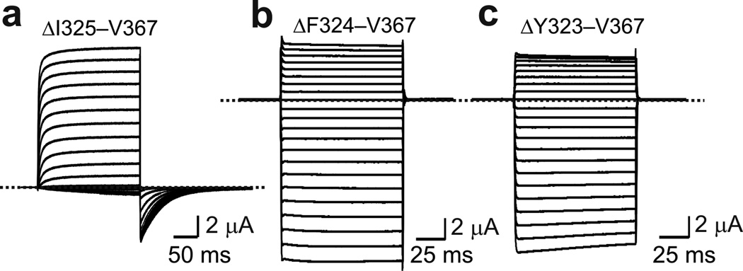
Deletion analysis of CTS3 through NTS4. (a–c) Currents of mutant channels elicited in the presence of 20 mM (a) or 100 mM (b and c) extracellular K+ by stepping membrane voltage from the −80 mV (a) or 0 mV (b and c) holding potential to between −70 mV (a) mV or −120 mV (b and c) and 80 mV in 10 mV increments. In the mutant channels, the sequences from I325 to V367 (a), F324 (b) or Y323 (c) were deleted and replaced by a glycine triplet. Currents shown were corrected for background currents obtained with 1 µM agitoxin-1 (AgTx1) present.
Engineering disulfide bonds between CTS3 and NTS4
Spatial relations between residues in CTS3 and NTS4 have previously been examined electrophysiologically, where oxidizing agents were employed to induce a disulfide bond between individual mutant cysteine pairs in CTS3 and NTS4 or Cd2+ was used to bridge them. In Kv1.2–2.1 structure, the residues corresponding to I325 in CTS3 and I364 in NTS4 of the Shaker channel are neighbors. However, it was previously reported that in Xenopus oocytes, current of the I325C I364C double mutant was insensitive to CuSO4 plus phenanthroline, reagents often used to induce disulfide bond formation36. Intriguingly, a subsequent study showed that addition of Cd2+ renders the I352C I364C double mutant channels conductive at hyperpolarized voltages37. For the following reason, we decided to screen for mutant cysteine pairs that ‘spontaneously’ form a disulfide bond. Two widely separated cysteines that approach one another only infrequently may normally have little chance to form a disulfide bond, whereas oxidizing reagents may dramatically enhance the probability of capturing these rare events and artificially “force” disulfide bond formation. This possibility is even more likely when a metal ion is used to bridge two cysteines.
To aid our search for potential cysteine pairs between CTS3 and NTS4, we used a construct in which, on the wild-type background, all three pairs of hydrophobic residues separating the four voltage-sensing arginines in NTS4 have been simultaneously replaced by six cysteines (Fig. 5a and b)34. On this hexa-cysteine background we mutated several residues in CTS3, one at a time, to cysteine and tested which help lock the channels in an open state (Fig. 5c–g). Unlike the previous study36, we did not incubate the oocytes in reducing reagent-containing solutions. Only the hexa-cysteine channels with I325C conducted current even at strongly hyperpolarized potentials (Fig. 5d). To identify which cysteine residue paired with I325C, we tested the six NTS4 cysteine mutations individually on the background of I325C (Fig. 5a). Only the I325C I364C double mutant exhibited apparently voltage-independent current (Fig. 6). This constitutively active current became fully voltage gated following extracellular exposure to the reducing agent DTT (Fig. 7a–d). Neither I325C nor I364C alone renders the channels constitutively open; both were required (Supplementary Fig. 3a–d). Therefore, I325C and I364C are a candidate pair that spontaneously forms a disulfide bond without added oxidizing reagents. Interestingly, when oocytes, following cRNA injection, were left overnight in a hyperpolarizing solution containing 2 mM K+ where channels would be mostly closed, a variable fraction of them expressed constitutively active current, the rest being voltage gated. On the other hand, when left overnight in a depolarizing solution (containing 50 mM K+), where channels would have a higher probability to be in the open state, nearly all oocytes expressed constitutively active current. This observed difference is consistent with the scenario that formation of the presumed disulfide bond is more likely in the open state.
Figure 5.

Cysteine point mutations of CTS3 in the presence of a hexa-cysteine mutation in NTS4. (a) Sequences of CTS3 and NTS4 without or with a hexa-cysteine mutation. (b–g) Current traces of mutant channels elicited by stepping from the −100 mV holding potential to between −80 mV and 80 mV in 10 mV increments. All six mutants contain a hexa-cysteine mutation as shown in a, without (b) or with (c–g) additional cysteine mutation in CTS3, as indicated. Currents shown in d were corrected for background currents obtained with 1 µM AgTx1 present.
Figure 6.

Cysteine mutation of individual hydrophobic residues in NTS4 in the presence of I325C in CTS3. Current traces of mutant channels elicited by stepping from the −100 mV holding potential to between −80 mV and 80 mV in 10 mV increments. All six mutants contain the I325C mutation in CTS3 and an additional cysteine mutation in NTS4, as indicated. Currents of the I325C I364C double mutant were corrected for background currents obtained with 1 µM AgTx1 present.
Figure 7.

Cysteine pairs between CTS3 and NTS4 that lock the channels in the open state. (a) Sequences of CTS3 and NTS4 of Shaker and Kv1.2–2.1 channels. The residue pairs in the Shaker sequence, whose substitution by cysteine lock the channel in the open state, are colored lime and blue. Corresponding residues in the Kv1.2–2.1 sequence are similarly colored. (b) Structure of Kv1.2–2.1’s CTS3 through NTS4 (PDB: 2R9R). Colored sticks correspond to the colored residues in the Kv1.2–2.1 sequence in a. (c–f) Ionic currents of the I325C I364C (c and d) or T329C L361C (e and f) double mutant without (control) or with exposure to 1 mM DTT (d, a few minutes; f, overnight). Currents were elicited by stepping membrane voltage from −100 mV (c and e) or −120 mV (d and f) to 100 mV (c and e) or 50 mV (d and f) in 10 mV increments. Traces shown in c and e were corrected for background currents obtained with 1 µM AgTx1 present. (g–j) Gating currents of channels containing the W434F mutation and the I325C I364C (g and h) or T329C L361C (i and j) double mutation without (control) or with exposure to 1 mM DTT (h, a few minutes; j, overnight). Currents elicited by stepping membrane voltage from −140 mV to 0 mV in 10 mV increments. Bathing solutions contained 100 mM K+ (c–f) or 5 mM K+ plus 95 mM Na+ (g–j).
In the Kv1.2–2.1 structure, the residues corresponding to I325 and I364 are neighbors (Fig. 7a and b). One helical turn away in the extracellular direction, the residues corresponding to Shaker’s T329 in CTS3 and L361 in NTS4 are also neighbors. We therefore checked whether T329C and L361C also lock the channels in an open state. The T329C mutant remained fully voltage-gated current with or without DTT present, whereas the L361C mutant appeared to conduct small current at very hyperpolarized voltages, too small for accurate analysis (Supplementary Fig. 3e–h). This phenomenon may be related to the fact that L361C can form a disulfide bond with L361C of a different subunit38. In contrast, the T329C L361C double mutant exhibited marked constitutive current and became voltage gated only after long exposure to DTT (Fig. 7e and f). Thus, T329C and L361C may also spontaneously form a disulfide bond, locking the voltage sensor in an open state. As expected for mutants with locked voltage sensors, on the background of W434F (which eliminates ionic current) both the I325C I364C and T329C L361C double-mutant channels exhibited gating current only after exposure to DTT (Fig. 7g–j).
Biochemical study of disulfide bond formation
Whether oxidation of a given cysteine alters channel protein function may depend on the properties and steric packing of surrounding residues, including other cysteines. We therefore resorted to biochemical means to demonstrate the existence of true spontaneous disulfide bonds between I325C and I364C or T329C and L361C. We take the I325C and I364C pair to describe our strategy for confirming biochemically a covalent interaction between candidate cysteine pairs. Within the S3–S4 linker of both wild-type and double cysteine mutant constructs, we inserted a sequence that can be specifically cleaved by the tobacco etched virus (TEV) protease between S351 and S352 (Fig. 3a). The N-terminal end of the construct contains an epitope specifically bound by the “Flag” antibody. As expected, all these channels expressed voltage-gated currents under reducing conditions (Supplementary Fig. 4). If the pair of cysteines forms a disulfide bond, the I325C I364C double mutant protein will migrate on SDS-PAGE under non-reducing conditions as a full-length protein, regardless of whether it has been digested with TEV, as the fragments will be held together by the disulfide bond. Under reducing conditions, on the other hand, only the non-digested protein will appear as full-length. That was indeed the case on a Western blot (Fig. 8a). First, as expected, when only a Flag tag was added, the protein appeared full length with or without TEV digestion and with (lanes 6 and 7) or without (lanes 12 and 13) exposure to reducing agents. The calculated molecular weight of our full-length construct is 72 kDa but the sample ran slower and as distinct bands because of varying levels of glycosylation39. Second, under both reducing and non-reducing conditions and with the TEV site present but no cysteine mutations, the undigested protein appeared as full-length (lanes 2 and 8) and the digested as the N-terminal fragment (lanes 3 and 9), both recognized by the anti-Flag antibody. Third, when the I325C L364C double mutation was present as well, the protein ran full-length under either reducing or non-reducing conditions, provided it was not digested with TEV (lanes 4 and 10). Finally, following TEV digestion, the I325C L364C double mutation ran full-length only under non-reducing condition (lane 11) but behaved as its N-terminal fragment under reducing conditions (lane 5). We obtained similar results with the T329C and I361C pair (Fig. 8b). Here, the T329C I361C double mutant primarily formed an intra- not inter-subunit disulfide bond, although the L361C single mutant has previously been shown to form an inter-subunit disulfide bond38. These biochemical results demonstrate that a disulfide bond spontaneously forms between I325C and I364C or between T329C and L361C.
Figure 8.

Biochemical examination of disulfide bond formation between cysteine pairs in the paddle motif. (a and b) Western blots of purified recombinant wild-type Shaker protein and I325C I364C (a) or (b) T329C L361C double-cysteine mutant proteins prepared under reducing or non-reducing conditions and with or without TEV digestion. All tested proteins contain an N-terminal Flag epitope with or without a TEV site in the S3–S4 linker. Molecular weight standards (MWS) run in the leftmost lane.
Discussion
We investigated whether the paddle motif exists in Shaker channels in a biological membrane by engineering disulfide bonds between CTS3 and NTS4. We found that channels containing I364C in NTS4 and I325C in CTS3 are constitutively conductive, a condition reversed by DTT treatment (Fig. 7). Given the limited ability of electrophysiological studies to show disulfide bond formation, we used biochemical methods as well to substantiate the formation of a spontaneous disulfide bond between I325C and I364C (Fig. 8). These two residues are therefore contiguous in an open state of the Shaker channel. Since spatial proximity at a single locus does not establish a relatively parallel orientation between CTS3 and NTS4, we identified a second cysteine pair, T329C in CTS3 and L361C in NTS4, that also spontaneously form a disulfide bond (Figs. 7 and 8). Given that the counterparts of these two Shaker residues in the Kv1.2–2.1 structure are also contiguous, our demonstration of spontaneous disulfide bond formation by both the I325C I364C and T329C L361C pairs establishes the existence of the helix-turn-helix paddle motif in a Kv channel operating in a biological membrane.
In an open-state crystal structure of Kv1.2–2.1, NTS4 is largely exposed to the extracellular solution. While the precise position of S4 in the closed state remains uncertain, much evidence suggests that in going from open to closed state, NTS4 moves inward and likely reaches the general region formerly occupied by CTS44, 5, 20, 36, 37, 40–51. If so, NTS4 would approach NTS5 (from another subunit), which is arguably the most hydrophobic part of all six transmembrane segments. This is consistent with the finding that increased hydrophobicity of NTS4 favors the closed state34. Thus, if CTS3 and NTS4 move together, CTS3 may help reduce the free energy needed to move the charged NTS4 into the membrane. This scenario predicts that increased hydrophobicity of CTS3 would favor the closed state as in the case of NTS4.
Alternatively, formation of the paddle motif favors an open rather than a closed state. In the past, much of the voltage-sensor debate revolved around how the positively charged residues in S4 are stabilized in the membrane, leading to the realization that negatively charged residues and phospholipids provide the needed countercharges3, 9, 12, 52–54. Meanwhile, an important related energetics issue remains largely unexplored, namely, how to minimize the cost of exposing hydrophobic residues in NTS4 to water in the open state. Two relatively hydrophobic helices left in an aqueous solution would come close together to minimize their water exposure, a fundamental principle underlying de novo coil-coiled motif design55. Thus, formation of the paddle motif may serve to stabilize NTS4 in an open state by reducing water exposure of some of its hydrophobic residues. This second possibility makes a prediction opposite to the first, i.e., increasing the hydrophobicity of CTS3 should favor the open state. It also predicts that formation of a disulfide bond between CTS3 and NTS4 will lock the channel in the open state. These are indeed our findings (Figs. 1, 7 and 8). To shield each other and minimize water exposure, CTS3 and NTS4 need only come sufficiently close to squeeze out water molecules, not necessarily form a highly complementary interface between them, as is the case in the Kv1.2–2.1 structure.
The Kv1.2–2.1 structure shows CTS3 and NTS4 to be part of a larger hydrophobic system that appears to keep the chemical equilibrium toward the open state. In the open-state structure, S4 is “sandwiched” between hydrophobic S3 and S5 (Fig. 9a). The front side of S4 is also hydrophobic but, not being shielded by any part of the channel protein (Fig. 9a and b), it must implicitly be “solvated” by lipids. On the other hand, the positively charged residues all line up on the back side (Fig. 9c), interacting with their countercharges in S1–S3 (Fig. 9d). It is as though while S4 is partially shielded from water, lying comfortably between hydrophobic S3 and S5 and helping maintain the open state, the negative electric field acts on the positive charges on S4, providing the free energy for S4 to slide along the “well-greased tracks” toward the intracellular side, thereby causing the gate closure. It is thus understandable why some mutations of hydrophobic residues in S3 through S5 profoundly affect the gating equilibrium34, 56–59 (Fig. 1). Nature has solved the conundrum, that functionally critical, charged and hydrophobic residues in S4 require opposite types of environment, by positioning them in separate zones. The hallmark periodicity of voltage sensors – one charged residue for two hydrophobic residues – satisfies this zoning arrangement (Fig. 9). A large contribution of hydrophobic interactions to stabilizing an arrangement, that keeps S4 appropriately coiled and thus partitioned between two zones, would reduce the need for contributions from charge-charge interactions, thereby lowering the energy barrier for S4 to slide.
Figure 9.

Partial structures of Kv1.2–2.1. (a) Space filling model of S3–S5 where hydrophobic, polar, negatively charged and positively charged residues are colored orange, magenta, ruby, and blue, respectively (PDB: 2R9R). S4 is delineated in turquoise. (b) Model of S1–S6, with S1–S4 from one subunit and S5 and S6 from the adjacent subunit. S3–S5 are positioned and colored as in a, whereas S1, S2 and S6 are shown as cyan, light blue, and lime ribbons, respectively. (c and d) Back views of a and b, respectively. The dotted lines approximate the membrane boundaries, extracellular (EC) and intracellular (IC) sides above and below, respectively.
Upon hyperpolarization, NTS4 may move inward by as little as about 5 Å to enter the shallowest closed state and continue for another 10–15 Å before reaching the deepest closed state4, 5, 20, 36, 37, 40–51. Given that in the Kv1.2–2.1 structure, CTS3 and NTS4 do not appear to interact very strongly, CTS3 may not follow NTS4 lock step over a long distance. If so, NTS4 could drag the S3–S4 linker into the membrane, with and without tilting or bending CTS3. In this respect, we have found that either a disulfide bond between CTS3 and NTS4 or excessive shortening of the paddle sequence locks the Shaker channel in an open state (Figs. 4, 7 and 8).
As the primary voltage sensor, NTS4 exhibits remarkable tolerance for deletions and is thus highly flexible, a property allowing it to adapt to a changing environment among various gating states, e.g., the positively charged, voltage-sensing residues to readily find proper negatively charged partners. In contrast, CTS4 and the S4–S5 linker, which exhibit little tolerance to deletion mutations, act as a “delicate gear” to ensure essentially obligatory coupling of the voltage-caused NTS4 motion to that of the CTS6 gate. Given that the voltage-gating process involves movement of so many helices in the channel, the concept of a sequence of voltage-dependent packings-and-repackings of these helices may well capture the essence of structural changes underlying the process.
Atomic structures of voltage-gated channels have raised two fundamental questions: i) does the unexpected paddle-shaped, helix-turn-helix motif exist in a functional state of channels residing within a biological membrane, and ii) if so, what is its functional significance. Here, we describe evidence, both electrophysiological and biochemical, for the existence of this motif in an open state of a Kv channel operating in a biological membrane. We have also found that CTS3 acts as an extracellular hydrophobic stabilizer to help hold the voltage-sensing NTS4 in an open state. In a broader sense, S4 seems to act as a positively charged, voltage-sensitive hydrophobic “floater” suspended by hydrophobic S3 and S5 as well as membrane lipids so as to help ensure a tilt toward the open state of the chemical equilibrium of the gating process. A negative transmembrane potential acts on the positively charged residues in NTS4 to push S4 inward toward the intracellular solution, thereby tilting the gating equilibrium toward the closed state. This interplay between chemical and electric energy enables voltage-gated ion channels to exhibit, within the modest physiological voltage range, open probabilities from near zero to sufficiently high, thereby engendering the rapid electric signaling in excitable cells.
Methods
Mutagenesis and electrophysiological recordings
The cDNA of the Shaker channel with inactivation removed, defined as WT in this study, was cloned in the pGEMHess vector61–66. Mutant channel cDNAs were produced through PCR-based mutagenesis and confirmed with DNA sequencing. The cRNAs were synthesized with T7 polymerase using the corresponding cDNAs (linearized with Nhe 1) as templates. Xenopus oocytes were prepared and injected with cRNA as previously described67. They were stored at 18°C in a solution containing 2 mM or 50 mM K+ and with or without 1 mM DTT as specified in the text, and studied at least 16 hours later. Channel currents were recorded from oocytes (previously injected with appropriate cRNA) using a two-electrode voltage clamp amplifier (Warner OC-725C; Harvard Apparatus), filtered at 1 kHz, and sampled at 10 kHz using an analog-to-digital converter (Digidata 1322A; MDS Analytical Technologies) interfaced with a personal computer. pClamp8 software (MDS Analytical Technologies) was used for amplifier control and data acquisition. To elicit currents the voltage across the oocyte membrane was stepped from the holding potential to various test voltages specified for individual cases. The resistance of electrodes filled with 3 M KCl was about 0.2 MΩ. Unless specified otherwise, the bath solution contained (in mM): 100 K+, 0.3 CaCl2, 1 MgCl2 and 10 HEPES; pH was adjusted to 7.6 with KOH. In some cases, ionic currents were corrected for background current using the P/4 protocol or using templates obtained in the presence of 1 µM AgTx1 (Kd ≈ 0.1 nM)68. Gating currents were isolated with the P/4 protocol1. Data analysis and curve fitting were performed with OriginPro 8 (OriginLab Corp.). The figures were made using OriginPro 8, PyMOL 1.0 (DeLano Scientific), CorelDRAW X4 (Corel Corp.), and Adobe Illustrator (Adobe).
Biochemical assays
All constructs contain an N-terminal Flag epitope sequence (DYKDDDDK) and a C-terminal His8 tag. Mutant constructs contain a site for the TEV protease (ENLYFQGS) inserted between Ser351 and Ser352 in the S3–S4 linker, with or without a double cysteine mutation (I325C I364C or T329C L361C) in CTS3 and NTS4. For protein expression, 200 oocytes were injected with a given cRNA and stored at 16°C in a solution containing (in mM): 50 KCl, 50 NaCl, 1.8 CaCl2, 1 MgCl2, 5 HEPES (pH 7.5) and gentamycin (5 µg/mL) for 72 hours. Prior to isolating the membrane, oocytes were exposed to 5 mM N-Ethylmaleimide for 15 minutes in the dark to block free sulfhydryl groups, then rinsed and homogenized in ice cold buffer A containing: 400 mM KCl, 5 mM 1,4-Piperazinediethanesulfonic acid (pH 6.8 adjusted with KOH), 10% sucrose (w/v) and six protease inhibitors (500 µM 4-[(2-Aminoethyl)]benzenesulfonyl fluoride, 10 µM E-64, 1 µM pepstatin A, 1 µg/mL aprotinin, 1 µg/mL leupeptin, and 2 mM p-aminobenzamidine). The homogenate was overlaid on a 10–20–50% discontinuous sucrose gradient in buffer A and centrifuged at 170,000 g for 30 minutes at 4°C. The fraction containing the crude membrane pieces was extracted from the 20–50% sucrose interface, diluted 3-fold with cold buffer A without protease inhibitors, and centrifuged again as above. The membrane pellet was resuspended in 20 µL of buffer B (300 mM sucrose, 100 mM KCl, and 5 mM MOPS; pH 6.8). The samples were diluted 500 fold with buffer B containing 0.5 mM EDTA and 3 mM reduced/oxidized glutathione in 10 : 1 ratio and digested with TEV (40 µg/mL) at 4°C overnight. After being concentrated 30 fold, the samples were mixed with 6 X Laemmli buffer (300mM Tris-HCl at pH 6.8, 10% SDS, 30% glycerol and 0.012% bromophenol blue) with or without the reducing agent 2-mercaptoethanol (10%), boiled for 3 minutes, and loaded onto a 10% SDS-PAGE gel. Samples on the SDS-PAGE gel were transferred onto a methanol-activated PVDF membrane using the wet electroblotting method. The PVDF membranes with the transferred samples were rinsed with Buffer C (1×TBS, 0.05% Tween-20) and incubated in Blotto solution (5% skim milk powder in Buffer C) for 1 hour and probed with mouse monoclonal anti-Flag M2 antibody (Sigma, cat. No. F3165 0.5–10mg/mL, using a 1:1,000 dilution to make 5 µg/mL) in Blotto solution at 4°C overnight. Membranes were then washed three times with Buffer C (5 minutes each) and probed (in Buffer C for 50 minutes) with rabbit polyclonal anti-mouse IgG antibody conjugated with horseradish peroxidase (General Electric, cat. No. NA931V, 1–3mg/mL, using 1:10,000 dilution to make 0.2 µg/mL). The membranes were washed again as above and antibody-targeted proteins were visualized using a standard horseradish peroxidase-based chemiluminescence detection method (ImageQuant LAS 4000, General Electric). Unless specified otherwise, all processes were performed at room temperature.
Supplementary Material
ACKNOWLEDGMENTS
We thank P. De Weer (University of Pennsylvania) for critical review of our manuscript. This study was supported by grant GM55560 from the National Institutes of Health. Z.L. is an investigator of the Howard Hughes Medical Institute.
Footnotes
AUTHOR CONTRIBUTIONS
Y.X., Y.R., H.-G.S., J.Y. and Z.L. designed research; Y.X., Y.R., H.-G.S., J.Y. and Z.L performed experiments; Y.X., Y.R., H.-G.S. and J.Y. analyzed data; Y.X., Y.R., J.Y. and Z.L wrote the manuscript.
References
- 1.Armstrong CM, Bezanilla F. Currents related to movement of the gating particles of the sodium channels. Nature. 1973;242:459–461. doi: 10.1038/242459a0. [DOI] [PubMed] [Google Scholar]
- 2.Noda M, et al. Primary structure of Electrophorus electricus sodium channel deduced from cDNA sequence. Nature. 1984;312:121–127. doi: 10.1038/312121a0. [DOI] [PubMed] [Google Scholar]
- 3.Catterall WA. Molecular properties of voltage-sensitive sodium channels. Annu. Rev. Biochem. 1986;55:953–985. doi: 10.1146/annurev.bi.55.070186.004513. [DOI] [PubMed] [Google Scholar]
- 4.Yang N, George AL, Jr, Horn R. Molecular basis of charge movement in voltage-gated sodium channels. Neuron. 1996;16:113–122. doi: 10.1016/s0896-6273(00)80028-8. [DOI] [PubMed] [Google Scholar]
- 5.Larsson HP, Baker OS, Dhillon DS, Isacoff EY. Transmembrane movement of the shaker K+ channel S4. Neuron. 1996;16:387–397. doi: 10.1016/s0896-6273(00)80056-2. [DOI] [PubMed] [Google Scholar]
- 6.Mannuzzu LM, Moronne MM, Isacoff EY. Direct physical measure of conformational rearrangement underlying potassium channel gating. Science. 1996;271:213–216. doi: 10.1126/science.271.5246.213. [DOI] [PubMed] [Google Scholar]
- 7.Stuhmer W, et al. Structural parts involved in activation and inactivation of the sodium channel. Nature. 1989;339:597–603. doi: 10.1038/339597a0. [DOI] [PubMed] [Google Scholar]
- 8.Papazian DM, Timpe LC, Jan YN, Jan LY. Alteration of voltage-dependence of Shaker potassium channel by mutations in the S4 sequence. Nature. 1991;349:305–310. doi: 10.1038/349305a0. [DOI] [PubMed] [Google Scholar]
- 9.Papazian DM, et al. Electrostatic interactions of S4 voltage sensor in Shaker K+ channel. Neuron. 1995;14:1293–1301. doi: 10.1016/0896-6273(95)90276-7. [DOI] [PubMed] [Google Scholar]
- 10.Liman ER, Hess P, Weaver F, Koren G. Voltage-sensing residues in the S4 region of a mammalian K+ channel. Nature. 1991;353:752–756. doi: 10.1038/353752a0. [DOI] [PubMed] [Google Scholar]
- 11.Aggarwal SK, MacKinnon R. Contribution of the S4 segment to gating charge in the Shaker K+ channel. Neuron. 1996;16:1169–1177. doi: 10.1016/s0896-6273(00)80143-9. [DOI] [PubMed] [Google Scholar]
- 12.Seoh SA, Sigg D, Papazian DM, Bezanilla F. Voltage-sensing residues in the S2 and S4 segments of the Shaker K+ channel. Neuron. 1996;16:1159–1167. doi: 10.1016/s0896-6273(00)80142-7. [DOI] [PubMed] [Google Scholar]
- 13.Schoppa NE, McCormack K, Tanouye MA, Sigworth FJ. The size of gating charge in wild-type and mutant Shaker potassium channels. Science. 1992;255:1712–1715. doi: 10.1126/science.1553560. [DOI] [PubMed] [Google Scholar]
- 14.Islas LD, Sigworth FJ. Voltage sensitivity and gating charge in Shaker and Shab family potassium channels. J. Gen. Physiol. 1999;114:723–742. doi: 10.1085/jgp.114.5.723. [DOI] [PMC free article] [PubMed] [Google Scholar]
- 15.Zagotta WN, Hoshi T, Dittman J, Aldrich RW. Shaker potassium channel gating. II: Transitions in the activation pathway. J Gen. Physiol. 1994;103:279–319. doi: 10.1085/jgp.103.2.279. [DOI] [PMC free article] [PubMed] [Google Scholar]
- 16.Long SB, Tao X, Campbell EB, MacKinnon R. Atomic structure of a voltage-dependent K+ channel in a lipid membrane-like environment. Nature. 2007;450:376–382. doi: 10.1038/nature06265. [DOI] [PubMed] [Google Scholar]
- 17.Pless SA, Galpin JD, Niciforovic AP, Ahern CA. Contributions of counter-charge in a potassium channel voltage-sensor domain. Nat. Chem Biol. 2011;7:617–623. doi: 10.1038/nchembio.622. [DOI] [PMC free article] [PubMed] [Google Scholar]
- 18.Starace DM, Bezanilla F. A proton pore in a potassium channel voltage sensor reveals a focused electric field. Nature. 2004;427:548–553. doi: 10.1038/nature02270. [DOI] [PubMed] [Google Scholar]
- 19.Ahern CA, Horn R. Focused electric field across the voltage sensor of potassium channels. Neuron. 2005;48:25–29. doi: 10.1016/j.neuron.2005.08.020. [DOI] [PubMed] [Google Scholar]
- 20.Tao X, Lee A, Limapichat W, Dougherty DA, MacKinnon R. A gating charge transfer center in voltage sensors. Science. 2010;328:67–73. doi: 10.1126/science.1185954. [DOI] [PMC free article] [PubMed] [Google Scholar]
- 21.Liu Y, Holmgren M, Jurman ME, Yellen G. Gated access to the pore of a voltage-dependent K+ channel. Neuron. 1997;19:175–184. doi: 10.1016/s0896-6273(00)80357-8. [DOI] [PubMed] [Google Scholar]
- 22.Hackos DH, Chang TH, Swartz KJ. Scanning the intracellular S6 activation gate in the shaker K+ channel. J. Gen. Physiol. 2002;119:521–532. doi: 10.1085/jgp.20028569. [DOI] [PMC free article] [PubMed] [Google Scholar]
- 23.Doyle DA, et al. The structure of the potassium channel: molecular basis of K+ conduction and selectivity. Science. 1998;280:69–77. doi: 10.1126/science.280.5360.69. [DOI] [PubMed] [Google Scholar]
- 24.Armstrong CM. Interaction of tetraethylammonium ion derivatives with the potassium channels of giant axons. J. Gen. Physiol. 1971;58:413–437. doi: 10.1085/jgp.58.4.413. [DOI] [PMC free article] [PubMed] [Google Scholar]
- 25.Lu Z, Klem AM, Ramu Y. Ion conduction pore is conserved among potassium channels. Nature. 2001;413:809–813. doi: 10.1038/35101535. [DOI] [PubMed] [Google Scholar]
- 26.Lu Z, Klem AM, Ramu Y. Coupling between voltage sensors and activation gate in voltage-gated K+ channels. J. Gen. Physiol. 2002;120:663–676. doi: 10.1085/jgp.20028696. [DOI] [PMC free article] [PubMed] [Google Scholar]
- 27.Tristani-Firouzi M, Chen J, Sanguinetti MC. Interactions between S4–S5 linker and S6 transmembrane domain modulate gating of HERG K+ channels. J Biol Chem. 2002;277:18994–19000. doi: 10.1074/jbc.M200410200. [DOI] [PubMed] [Google Scholar]
- 28.Long SB, Campbell EB, MacKinnon R. Voltage sensor of Kv1.2: structural basis of electromechanical coupling. Science. 2005;309:903–908. doi: 10.1126/science.1116270. [DOI] [PubMed] [Google Scholar]
- 29.Jiang Y, et al. X-ray structure of a voltage-dependent K+ channel. Nature. 2003;423:33–41. doi: 10.1038/nature01580. [DOI] [PubMed] [Google Scholar]
- 30.Long SB, Campbell EB, MacKinnon R. Crystal structure of a mammalian voltage-dependent Shaker family K+ channel. Science. 2005;309:897–903. doi: 10.1126/science.1116269. [DOI] [PubMed] [Google Scholar]
- 31.Payandeh J, Scheuer T, Zheng N, Catterall WA. The crystal structure of a voltage-gated sodium channel. Nature. 2011;475:353–358. doi: 10.1038/nature10238. [DOI] [PMC free article] [PubMed] [Google Scholar]
- 32.Payandeh J, Gamal El-Din TM, Scheuer T, Zheng N, Catterall WA. Crystal structure of a voltage-gated sodium channel in two potentially inactivated states. Nature. 2012;486:135–139. doi: 10.1038/nature11077. [DOI] [PMC free article] [PubMed] [Google Scholar]
- 33.Zhang X, et al. Crystal structure of an orthologue of the NaChBac voltage-gated sodium channel. Nature. 2012;486:130–134. doi: 10.1038/nature11054. [DOI] [PMC free article] [PubMed] [Google Scholar]
- 34.Xu Y, Ramu Y, Lu ZA. Shaker K+ channel with a miniature engineered voltage sensor. Cell. 2010;142:580–589. doi: 10.1016/j.cell.2010.07.013. [DOI] [PMC free article] [PubMed] [Google Scholar]
- 35.Alabi AA, Bahamonde MI, Jung HJ, Kim JI, Swartz KJ. Portability of paddle motif function and pharmacology in voltage sensors. Nature. 2007;450:370–375. doi: 10.1038/nature06266. [DOI] [PMC free article] [PubMed] [Google Scholar]
- 36.Broomand A, Elinder F. Large-scale movement within the voltage-sensor paddle of a potassium channel-support for a helical-screw motion. Neuron. 2008;59:770–777. doi: 10.1016/j.neuron.2008.07.008. [DOI] [PubMed] [Google Scholar]
- 37.Henrion U, et al. Tracking a complete voltage-sensor cycle with metal-ion bridges. Proc. Natl. Acad. Sci. U. S. A. 2012;109:8552–8557. doi: 10.1073/pnas.1116938109. [DOI] [PMC free article] [PubMed] [Google Scholar]
- 38.Aziz QH, Partridge CJ, Munsey TS, Sivaprasadarao A. Depolarization induces intersubunit cross-linking in a S4 cysteine mutant of the Shaker potassium channel. J Biol Chem. 2002;277:42719–42725. doi: 10.1074/jbc.M207258200. [DOI] [PubMed] [Google Scholar]
- 39.Laine M, et al. Atomic proximity between S4 segment and pore domain in Shaker potassium channels. Neuron. 2003;39:467–481. doi: 10.1016/s0896-6273(03)00468-9. [DOI] [PubMed] [Google Scholar]
- 40.Elliott DJ, et al. Molecular mechanism of voltage sensor movements in a potassium channel. EMBO J. 2004;23:4717–4726. doi: 10.1038/sj.emboj.7600484. [DOI] [PMC free article] [PubMed] [Google Scholar]
- 41.Phillips LR, et al. Voltage-sensor activation with a tarantula toxin as cargo. Nature. 2005;436:857–860. doi: 10.1038/nature03873. [DOI] [PubMed] [Google Scholar]
- 42.Ruta V, Chen J, MacKinnon R. Calibrated measurement of gating-charge arginine displacement in the KvAP voltage-dependent K+ channel. Cell. 2005;123:463–475. doi: 10.1016/j.cell.2005.08.041. [DOI] [PubMed] [Google Scholar]
- 43.Campos FV, Chanda B, Roux B, Bezanilla F. Two atomic constraints unambiguously position the S4 segment relative to S1 and S2 segments in the closed state of Shaker K channel. Proc. Natl. Acad. Sci. U. S. A. 2007;104:7904–7909. doi: 10.1073/pnas.0702638104. [DOI] [PMC free article] [PubMed] [Google Scholar]
- 44.Grabe M, Lai HC, Jain M, Jan YN, Jan LY. Structure prediction for the down state of a potassium channel voltage sensor. Nature. 2007;445:550–553. doi: 10.1038/nature05494. [DOI] [PubMed] [Google Scholar]
- 45.Posson DJ, Selvin PR. Extent of voltage sensor movement during gating of shaker K+ channels. Neuron. 2008;59:98–109. doi: 10.1016/j.neuron.2008.05.006. [DOI] [PMC free article] [PubMed] [Google Scholar]
- 46.Chakrapani S, Sompornpisut P, Intharathep P, Roux B, Perozo E. The activated state of a sodium channel voltage sensor in a membrane environment. Proc. Natl. Acad. Sci. U. S. A. 2010;107:5435–5440. doi: 10.1073/pnas.0914109107. [DOI] [PMC free article] [PubMed] [Google Scholar]
- 47.DeCaen PG, Yarov-Yarovoy V, Scheuer T, Catterall WA. Gating charge interactions with the S1 segment during activation of a Na+ channel voltage sensor. Proc. Natl. Acad. Sci. U. S. A. 2011;108:18825–18830. doi: 10.1073/pnas.1116449108. [DOI] [PMC free article] [PubMed] [Google Scholar]
- 48.Lin MC, Hsieh JY, Mock AF, Papazian DM. R1 in the Shaker S4 occupies the gating charge transfer center in the resting state. J Gen. Physiol. 2011;138:155–163. doi: 10.1085/jgp.201110642. [DOI] [PMC free article] [PubMed] [Google Scholar]
- 49.Hoshi T, Armstrong CM. Initial steps in the opening of a Shaker potassium channel. Proc. Natl. Acad. Sci. U. S. A. 2012;109:12800–12804. doi: 10.1073/pnas.1209665109. [DOI] [PMC free article] [PubMed] [Google Scholar]
- 50.Jensen MO, et al. Mechanism of voltage gating in potassium channels. Science. 2012;336:229–233. doi: 10.1126/science.1216533. [DOI] [PubMed] [Google Scholar]
- 51.Yarov-Yarovoy V, et al. Structural basis for gating charge movement in the voltage sensor of a sodium channel. Proc. Natl. Acad. Sci. U.S. A. 2012;109:E93–E102. doi: 10.1073/pnas.1118434109. [DOI] [PMC free article] [PubMed] [Google Scholar]
- 52.Armstrong CM. Sodium channels and gating currents. Physiol Rev. 1981;61:644–683. doi: 10.1152/physrev.1981.61.3.644. [DOI] [PubMed] [Google Scholar]
- 53.Schmidt D, Jiang QX, MacKinnon R. Phospholipids and the origin of cationic gating charges in voltage sensors. Nature. 2006;444:775–779. doi: 10.1038/nature05416. [DOI] [PubMed] [Google Scholar]
- 54.Xu Y, Ramu Y, Lu Z. Removal of phospho-head groups of membrane lipids immobilizes voltage sensors of K+ channels. Nature. 2008;451:826–829. doi: 10.1038/nature06618. [DOI] [PMC free article] [PubMed] [Google Scholar]
- 55.Woolfson DN. The design of coiled-coil structures and assemblies. Adv. Protein Chem. 2005;70:79–112. doi: 10.1016/S0065-3233(05)70004-8. [DOI] [PubMed] [Google Scholar]
- 56.Lopez GA, Jan YN, Jan LY. Hydrophobic substitution mutations in the S4 sequence alter voltage-dependent gating in Shaker K+ channels. Neuron. 1991;7:327–336. doi: 10.1016/0896-6273(91)90271-z. [DOI] [PubMed] [Google Scholar]
- 57.Smith-Maxwell CJ, Ledwell JL, Aldrich RW. Uncharged S4 residues and cooperativity in voltage-dependent potassium channel activation. J Gen. Physiol. 1998;111:421–439. doi: 10.1085/jgp.111.3.421. [DOI] [PMC free article] [PubMed] [Google Scholar]
- 58.Li-Smerin Y, Hackos DH, Swartz KJ. A localized interaction surface for voltage-sensing domains on the pore domain of a K+ channel. Neuron. 2000;25:411–423. doi: 10.1016/s0896-6273(00)80904-6. [DOI] [PubMed] [Google Scholar]
- 59.Soler-Llavina GJ, Chang TH, Swartz KJ. Functional interactions at the interface between voltage-sensing and pore domains in the Shaker K(v) channel. Neuron. 2006;52:623–634. doi: 10.1016/j.neuron.2006.10.005. [DOI] [PubMed] [Google Scholar]
- 60.Hessa T, et al. Molecular code for transmembrane-helix recognition by the Sec61 translocon. Nature. 2007;450:1026–1030. doi: 10.1038/nature06387. [DOI] [PubMed] [Google Scholar]
- 61.Tempel BL, Papazian DM, Schwarz TL, Jan YN, Jan LY. Sequence of a probable potassium channel component encoded at Shaker locus of Drosophila. Science. 1987;237:770–775. doi: 10.1126/science.2441471. [DOI] [PubMed] [Google Scholar]
- 62.Timpe LC, et al. Expression of functional potassium channels from Shaker cDNA in Xenopus oocytes. Nature. 1988;331:143–145. doi: 10.1038/331143a0. [DOI] [PubMed] [Google Scholar]
- 63.Pongs O, et al. Shaker encodes a family of putative potassium channel proteins in the nervous system of Drosophila. EMBO J. 1988;7:1087–1096. doi: 10.1002/j.1460-2075.1988.tb02917.x. [DOI] [PMC free article] [PubMed] [Google Scholar]
- 64.Kamb A, Tseng-Crank J, Tanouye MA. Multiple products of the Drosophila Shaker gene may contribute to potassium channel diversity. Neuron. 1988;1:421–430. doi: 10.1016/0896-6273(88)90192-4. [DOI] [PubMed] [Google Scholar]
- 65.Hoshi T, Zagotta WN, Aldrich RW. Biophysical and molecular mechanisms of Shaker potassium channel inactivation. Science. 1990;250:533–538. doi: 10.1126/science.2122519. [DOI] [PubMed] [Google Scholar]
- 66.Liman ER, Tytgat J, Hess P. Subunit stoichiometry of a mammalian K+ channel determined by construction of multimeric cDNAs. Neuron. 1992;9:861–871. doi: 10.1016/0896-6273(92)90239-a. [DOI] [PubMed] [Google Scholar]
- 67.Spassova M, Lu Z. Coupled ion movement underlies rectification in an inward-rectifier K+ channel. J Gen. Physiol. 1998;112:211–221. doi: 10.1085/jgp.112.2.211. [DOI] [PMC free article] [PubMed] [Google Scholar]
- 68.Garcia ML, Garcia-Calvo M, Hidalgo P, Lee A, MacKinnon R. Purification and characterization of three inhibitors of voltage-dependent K+ channels from Leiurus quinquestriatus var. hebraeus venom. Biochemistry. 1994;33:6834–6839. doi: 10.1021/bi00188a012. [DOI] [PubMed] [Google Scholar]
Associated Data
This section collects any data citations, data availability statements, or supplementary materials included in this article.