

Abstract
A prospective study was performed on neurosurgical samples from 18 patients to evaluate the use of full-field optical coherence tomography (FF-OCT) in brain tumor diagnosis.
FF-OCT captures en face slices of tissue samples at 1 μm resolution in 3D to a penetration depth of around 200 μm. A 1 cm2 specimen is scanned at a single depth and processed in about 5 min. This rapid imaging process is non-invasive and requires neither contrast agent injection nor tissue preparation, which makes it particularly well suited to medical imaging applications.
Temporal chronic epileptic parenchyma and brain tumors such as meningiomas, low-grade and high-grade gliomas, and choroid plexus papilloma were imaged. A subpopulation of neurons, myelin fibers and CNS vasculature were clearly identified. Cortex could be discriminated from white matter, but individual glial cells such as astrocytes (normal or reactive) or oligodendrocytes were not observable.
This study reports for the first time on the feasibility of using FF-OCT in a real-time manner as a label-free non-invasive imaging technique in an intraoperative neurosurgical clinical setting to assess tumorous glial and epileptic margins.
Abbreviations: FF-OCT, full field optical coherence tomography; OCT, optical coherence tomography
Keywords: Optical imaging, Digital pathology, Brain imaging, Brain tumor, Glioma
Highlights
-
•
Demonstration of full-field optical coherence tomography imaging of human brain samples
-
•
Potential as an intraoperative tool for determining tissue architecture and content in minutes
-
•
Myelin fibers, neurons, microcalcifications, tumor cells, microcysts, and vessels identified
-
•
Good correspondence with histological slides, allowing clinical use for tissue selection
1. Introduction
1.1. Primary CNS tumors
Primary central nervous system (CNS) tumors represent a heterogeneous group of tumors with benign, malignant and slow-growing evolution. In France, 5000 new cases of primary CNS tumors are detected annually (Rigau et al., 2011). Despite considerable progress in diagnosis and treatment, the survival rate following a malignant brain tumor remains low and 3000 deaths are reported annually from CNS tumors in France (INCa, 2011). Overall survival from brain tumors depends on the complete resection of the tumor mass, as identified through postoperative imaging, associated with updated adjuvant radiation therapy and chemotherapy regimen for malignant tumors (Soffietti et al., 2010). Therefore, there is a need to evaluate the completeness of the tumor resection at the end of the surgical procedure, as well as to identify the different components of the tumor interoperatively, i.e. tumor tissue, necrosis, infiltrated parenchyma (Kelly et al., 1987). In particular, the persistence of non-visible tumorous tissue or isolated tumor cells infiltrating brain parenchyma may lead to additional resection.
For low-grade tumors located close to eloquent brain areas, a maximally safe resection that spares functional tissue warrants the current use of intraoperative techniques that guide a more complete tumor resection. During awake surgery, speech or fine motor skills are monitored, while cortical and subcortical stimulations are performed to identify functional areas (Sanai et al., 2008). Intraoperative MRI provides images of the surgical site as well as tomographic images of the whole brain that are sufficient for an approximate evaluation of the abnormal excised tissue, but offers low resolution (typically 1 to 1.5 mm) and produces artifacts at the air-tissue boundary of the surgical site.
Histological and immunohistochemical analyses of neurosurgical samples remain the current gold standard method used to analyze tumorous tissue due to advantages of sub-cellular level resolution and high contrast. However, these methods require lengthy (12 to 72 h), complex multiple steps, and use of carcinogenic chemical products that would not be technically possible intra-operatively. In addition, the number of histological slides that can be reviewed and analyzed by a pathologist is limited, and it defines the number and size of sampled locations on the tumor, or the surrounding tissue.
To obtain histology-like information in a short time period, intraoperative cytological smear tests are performed. However tissue architecture information is thereby lost and the analysis is carried out on only a limited area of the sample (1 mm × 1 mm).
Intraoperative optical imaging techniques are recently developed high resolution imaging modalities that may help the surgeon to identify the persistence of tumor tissue at the resection boundaries. Using a conventional operating microscope with Xenon lamp illumination gives an overall view of the surgical site, but performance is limited by the poor discriminative capacity of the white light illumination at the surgical site interface. Better discrimination between normal and tumorous tissues has been obtained using fluorescence properties of tumor cells labeled with preoperatively administered 5-ALA. Tumor tissue shows a strong ALA-induced PPIX fluorescence at 635 nm and 704 nm when the operative field is illuminated with a 440 nm-filtered lamp. More complete resections of high-grade gliomas have been demonstrated using 5-ALA fluorescence guidance (Stummer et al., 2000), however brain parenchyma infiltrated by isolated tumor cells is not fluorescent, reducing the interest of this technique when resecting low-grade gliomas.
Refinement of this induced fluorescence technique has been achieved using a confocal microscope and intraoperative injection of sodium fluorescein. A 488 nm laser illuminates the operative field and tissue contact analysis is performed using a handheld surgical probe (field of view less than 0.5 × 0.5 mm) which scans the fluorescence of the surgical interface at the 505–585 nm band. Fluorescent isolated tumor cells are clearly identified at depths from 0 to 500 μm from the resection border (Sanai et al., 2011), demonstrating the potential of this technique in low-grade glioma resection.
Reviewing the state-of-the-art, a need is identified for a quick and reliable method of providing the neurosurgeon with architectural and cellular information without the need for injection or oral intake of exogenous markers in order to guide the neurosurgeon and optimize surgical resections.
1.2. Full-field optical coherence tomography
Introduced in the early 1990s (Huang et al., 1991), optical coherence tomography (OCT) uses interference to precisely locate light deep inside tissue. The photons coming from the small volume of interest are distinguished from light scattered by the other parts of the sample by the use of an interferometer and a light source with short coherence length. Only the portion of light with the same path length as the reference arm of the interferometer, to within the coherence length of the source (typically a few μm), will produce interference. A two-dimensional B-scan image is captured by scanning. Recently, the technique has been improved, mainly in terms of speed and sensitivity, through spectral encoding (De Boer et al., 2003; Leitgeb et al., 2003; Wojtkowski et al., 2002).
A recent OCT technique called full-field optical coherence tomography (FF-OCT) enables both a large field of view and high resolution over the full field of observation (Dubois et al., 2002, 2004). This allows navigation across the wide field image to follow the morphology at different scales and different positions. FF-OCT uses a simple halogen or light-emitting diode (LED) light source for full field illumination, rather than lasers and point-by-point scanning components required for conventional OCT. The illumination level is low enough to maintain the sample integrity: the power incident on the sample is less than 1 mW/mm2 using deep red and near infrared light. FF-OCT provides the highest OCT 3D resolution of 1.5 × 1.5 × 1 μm3 (X × Y × Z) on unprepared label-free tissue samples down to depths of approximately 200 μm–300 μm (tissue-dependent) over a wide field of view that allows digital zooming down to the cellular level. Interestingly, it produces en face images in the native field view (rather than the cross-sectional images of conventional OCT), which mimic the histology process, thereby facilitating the reading of images by pathologists. Moreover, as for conventional OCT, it does not require tissue slicing or modification of any kind (i.e. no tissue fixation, coloration, freezing or paraffin embedding). FF-OCT image acquisition and processing time is less than 5 min for a typical 1 cm2 sample (Assayag et al., 2013) and the imaging performance has been shown to be equivalent in fresh or fixed tissue (Assayag et al., 2013; Dalimier and Salomon, 2012). In addition, FF-OCT intrinsically provides digital images suitable for telemedicine.
Numerous studies have been published over the past two decades demonstrating the suitability of OCT for in vivo or ex vivo diagnosis. OCT imaging has been previously applied in a variety of tissues such as the eye (Grieve et al., 2004; Swanson et al., 1993), upper aerodigestive tract (Betz et al., 2008; Chen et al., 2007; Ozawa et al., 2009), gastrointestinal tract (Tearney et al., 1998), and breast tissue and lymph nodes (Adie and Boppart, 2009; Boppart et al., 2004; Hsiung et al., 2007; Luo et al., 2005; Nguyen et al., 2009; Zhou et al., 2010; Zysk and Boppart, 2006).
In the CNS, published studies that evaluate OCT (Bizheva et al., 2005; Böhringer et al., 2006, 2009; Boppart, 2003; Boppart et al., 1998) using time-domain (TD) or spectral domain (SD) OCT systems had insufficient resolution (10 to 15 μm axial) for visualization of fine morphological details. A study of 9 patients with gliomas carried out using a TD-OCT system led to classification of the samples as malignant versus benign (Böhringer et al., 2009). However, the differentiation of tissues was achieved by considering the relative attenuation of the signal returning from the tumorous zones in relation to that returning from healthy zones. The classification was not possible by real recognition of CNS microscopic structures. Another study showed images of brain microstructures obtained with an OCT system equipped with an ultra-fast laser that offered axial and lateral resolution of 1.3 μm and 3 μm respectively (Bizheva et al., 2005). In this way, it was possible to differentiate malignant from healthy tissue by the presence of blood vessels, microcalcifications and cysts in the tumorous tissue. However the images obtained were small (2 mm × 1 mm), captured on fixed tissue only and required use of an expensive large laser thereby limiting the possibility for clinical implementation.
Other studies have focused on animal brain. In rat brain in vivo, it has been shown that optical coherence microscopy (OCM) can reveal neuronal cell bodies and myelin fibers (Srinivasan et al., 2012), while FF-OCT can also reveal myelin fibers (Ben Arous et al., 2011), and movement of red blood cells in vessels (Binding et al., 2011).
En face images captured with confocal reflectance microscopy can closely resemble FF-OCT images. For example, a prototype system used by Wirth et al. (2012) achieves lateral and axial resolution of 0.9 μm and 3 μm respectively. However small field size prevents viewing of wide-field architecture and slow acquisition speed prohibits the implementation of mosaicking. In addition, the poorer axial resolution and lower penetration depth of confocal imaging in comparison to FF-OCT limit the ability to reconstruct cross-sections from the confocal image stack.
This study is the first to analyze non-tumorous and tumorous human brain tissue samples using FF-OCT.
2. Materials and methods
2.1. Instrument
The experimental arrangement of FF-OCT (Fig. 1A) is based on a configuration that is referred to as a Linnik interferometer (Dubois et al., 2002). A halogen lamp is used as a spatially incoherent source to illuminate the full field of an immersion microscope objective at a central wavelength of 700 nm, with spectral width of 125 nm. The signal is extracted from the background of incoherent backscattered light using a phase-shifting method implemented in custom-designed software. This study was performed on a commercial FF-OCT system (LightCT, LLTech, France).
Fig. 1.

System schematic (A), photograph (B), sample holder close up (C), and sample close up (D).
Capturing “en face” images allows easy comparison with histological sections. The resolution, pixel number and sampling requirements result in a native field of view that is limited to about 1 mm2. The sample is moved on a high precision mechanical platform and a number of fields are stitched together (Beck et al., 2000) to display a significant field of view. The FF-OCT microscope is housed in a compact setup (Fig. 1B) that is about the size of a standard optical microscope (310 × 310 × 800 mm L × W × H).
2.2. Imaging protocol
All images presented in this study were captured on fresh brain tissue samples from patients operated on at the Neurosurgery Department of Sainte-Anne Hospital, Paris. Informed and written consent was obtained in all cases following the standard procedure at Sainte-Anne Hospital from patients who were undergoing surgical intervention. Fresh samples were collected from the operating theater immediately after resection and sent to the pathology department. A pathologist dissected each sample to obtain a 1–2 cm2 piece and made a macroscopic observation to orientate the specimen in order to decide which side to image. The sample was immersed in physiological serum, placed in a cassette, numbered, and brought to the FF-OCT imaging facility in a nearby laboratory (15 min distant) where the FF-OCT images were captured. The sample was placed in a custom holder with a coverslip on top (Fig. 1C, D). The sample was raised on a piston to rest gently against the coverslip in order to flatten the surface and so optimize the image capture. The sample is automatically scanned under a 10 × 0.3 numerical aperture (NA) immersion microscope objective. The immersion medium is a silicone oil of refractive index close to that of water, chosen to optimize index matching and slow evaporation. The entire area of each sample was imaged at a depth of 20 μm beneath the sample surface. This depth has been reported to be optimal for comparison of FF-OCT images to histology images in a previous study on breast tissue (Assayag et al., 2013). There are several reasons for the choice of imaging depth: firstly, histology was also performed at approximately 20 μm from the edge of the block, i.e. the depth at which typically the whole tissue surface begins to be revealed. Secondly, FF-OCT signal is attenuated with depth due to multiple scattering in the tissue, and resolution is degraded with depth due to aberrations. The best FF-OCT images are therefore captured close to the surface, and the best matching is achieved by attempting to image at a similar depth as the slice in the paraffin block. It was also possible to capture image stacks down to several hundred μm in depth (where penetration depth is dependent on tissue type), for the purpose of reconstructing a 3D volume and imaging layers of neurons and myelin fibers. An example of such a stack in the cerebellum is shown as a video (Video 2) in supplementary material. Once FF-OCT imaging was done, each sample was immediately fixed in formaldehyde and returned to the pathology department where it underwent standard processing in order to compare the FF-OCT images to histology slides.
All images presented in this study were captured on fresh brain tissue samples from patients operated on at the Neurosurgery Department of Sainte-Anne Hospital, Paris. Informed and written consent was obtained in all cases following the standard procedure at Sainte-Anne Hospital from patients who were undergoing surgical intervention. Fresh samples were collected from the operating theater immediately after resection and sent to the pathology department. A pathologist dissected each sample to obtain a 1–2 cm2 piece and made a macroscopic observation to orientate the specimen in order to decide which side to image. The sample was immersed in physiological serum, placed in a cassette, numbered, and brought to the FF-OCT imaging facility in a nearby laboratory (15 min distant) where the FF-OCT images were captured. The sample was placed in a custom holder with a coverslip on top (Fig. 1C, D). The sample was raised on a piston to rest gently against the coverslip in order to flatten the surface and so optimize the image capture. The sample is automatically scanned under a 10 × 0.3 numerical aperture (NA) immersion microscope objective. The immersion medium is a silicone oil of refractive index close to that of water, chosen to optimize index matching and slow evaporation. The entire area of each sample was imaged at a depth of 20 μm beneath the sample surface. This depth has been reported to be optimal for comparison of FF-OCT images to histology images in a previous study on breast tissue (Assayag et al., 2013). There are several reasons for the choice of imaging depth: firstly, histology was also performed at approximately 20 μm from the edge of the block, i.e. the depth at which typically the whole tissue surface begins to be revealed. Secondly, FF-OCT signal is attenuated with depth due to multiple scattering in the tissue, and resolution is degraded with depth due to aberrations. The best FF-OCT images are therefore captured close to the surface, and the best matching is achieved by attempting to image at a similar depth as the slice in the paraffin block. It was also possible to capture image stacks down to several hundred μm in depth (where penetration depth is dependent on tissue type), for the purpose of reconstructing a 3D volume and imaging layers of neurons and myelin fibers. An example of such a stack in the cerebellum is shown as a video (Video 2) in supplementary material. Once FF-OCT imaging was done, each sample was immediately fixed in formaldehyde and returned to the pathology department where it underwent standard processing in order to compare the FF-OCT images to histology slides.
2.3. Matching FF-OCT to histology
The intention in all cases was to match as closely as possible to histology. FF-OCT images were captured 20 μm below the surface. Histology slices were captured 20 μm from the edge of the block. However the angle of the inclusion is hard to control and so some difference in the angle of the plane always exists when attempting matching. Various other factors that can cause differences stem from the histology process — fixing, dehydrating, paraffin inclusion etc. all alter the tissue and so precise correspondence can be challenging. Such difficulties are common in attempting to match histology to other imaging modalities (e.g. FF-OCT Assayag et al., 2013; OCT Bizheva et al., 2005; confocal microscopy Wirth et al., 2012).
An additional parameter in the matching process is the slice thickness. Histology slides were 4 μm in thickness while FF-OCT optical slices have a 1 μm thickness. The finer slice of the FF-OCT image meant that lower cell densities were perceived on the FF-OCT images (in those cases where individual cells were seen, e.g. neurons in the cortex). This difference in slice thickness affects the accuracy of the FF-OCT to histology match. In order to improve matching, it would have been possible to capture four FF-OCT slices in 1 μm steps and sum the images to mimic the histology thickness. However, this would effectively degrade the resolution, which was deemed undesirable in evaluating the capacities of the FF-OCT method.
3. Results
18 samples from 18 adult patients (4 males, 14 females) of age range 19–81 years have been included in the study: 1 mesial temporal lobe epilepsy and 1 cerebellum adjacent to a pulmonary adenocarcinoma metastasis (serving as the non-tumor brain samples), 7 diffuse supratentorial gliomas (4 WHO grade II, 3 WHO grade III), 5 meningiomas, 1 hemangiopericytoma, and 1 choroid plexus papilloma. Patient characteristics are detailed in Table 1.
Table 1.
Summary of patients, cases, and corresponding figure key.
| Patient number | Age | Sex | Sample type | Figure # |
|---|---|---|---|---|
| R376 | 20 | F | Temporal neocortex from mesial temporal lobe epilepsy | 2 |
| R577 | 54 | M | Temporal neocortex from mesial temporal lobe epilepsy | – |
| R384 | 19 | F | Hippocampal formation from mesial temporal lobe epilepsy | 3 |
| R576 | 49 | M | Normal cerebellum adjacent to a pulmonary adenocarcinoma metastasis | 4 |
| R377 | 81 | F | Fibroblastic meningioma grade 1 | – |
| R378 | 56 | M | Atypical meningioma grade 2 | – |
| R393 | 35 | F | Transitional meningioma grade 1 | – |
| R512 | 66 | F | Atypical meningioma grade 2 | 5 |
| R517 | 73 | F | Atypical meningioma grade 2 | – |
| R518 | 38 | F | Hemangiopericytoma grade 2 | 6 |
| R409 | 25 | M | Choroid plexus papilloma | 7 |
| R379 | 25 | F | Fibrillary astrocytoma grade 2 | – |
| R410 | 65 | F | Oligo-astrocytoma grade 3 | – |
| R513 | 51 | F | Astrocytoma grade 2 | 8 |
| R520 | 40 | F | Oligo-astrocytoma grade 2 | 8 |
| R535 | 40 | F | Oligo-astrocytoma grade 3 | 8 |
| R569 | 32 | F | Gemistocytic astrocytoma grade 2 | – |
| R573 | 58 | F | Oligodendroglioma grade 3 | 8 |
3.1. FF-OCT imaging identifies myelinated axon fibers, neuronal cell bodies and vasculature in the human epileptic brain and cerebellum
The cortex and the white matter are clearly distinguished from one another (Fig. 2). Indeed, a subpopulation of neuronal cell bodies (Fig. 2B, C) as well as myelinated axon bundles leading to the white matter could be recognized (Fig. 2D, E). Neuronal cell bodies appear as dark triangles (Fig. 2C) in relation to the bright surrounding myelinated environment. The FF-OCT signal is produced by backscattered photons from tissues of differing refractive indices. The number of photons backscattered from the nuclei in neurons appears to be too few to produce a signal that allows their differentiation from the cytoplasm, and therefore the whole of the cell body (nucleus plus cytoplasm) appears dark.
Fig. 2.

Cortex is distinguished from white matter. (A) Cortex appears gray. (B–C) Neuronal cell bodies (arrows), (D–E) myelinated axon bundles (arrow) leading to white matter, and (F–G) vasculature (arrow). (B and F) Hemalun and phloxin stainings and (D) Luxol blue staining.
Rectangles indicate locations of zooms. Scale bars show 500 μm (A), 50 μm (B, C, F, G) and 80 μm (D, E).
Myelinated axons are numerous, well discernible as small fascicles and appear as bright white lines (Fig. 2E). As the cortex does not contain many myelinated axons, it appears dark gray. Brain vasculature is visible (Fig. 2F and G), and small vessels are distinguished by a thin collagen membrane that appears light gray. Video 1 in supplementary material shows a movie composed of a series of en face 1 μm thick optical slices captured over 100 μm into the depth of the cortex tissue. The myelin fibers and neuronal cell bodies are seen in successive layers.
Myelinated axons are numerous, well discernible as small fascicles and appear as bright white lines (Fig. 2E). As the cortex does not contain many myelinated axons, it appears dark gray. Brain vasculature is visible (Fig. 2F and G), and small vessels are distinguished by a thin collagen membrane that appears light gray. Video 1 in supplementary material shows a movie composed of a series of en face 1 μm thick optical slices captured over 100 μm into the depth of the cortex tissue. The myelin fibers and neuronal cell bodies are seen in successive layers.
The different regions of the human hippocampal formation are easily recognizable (Fig. 3). Indeed, CA1 field and its stratum radiatum, CA4 field, the hippocampal fissure, the dentate gyrus, and the alveus are easily distinguishable. Other structures become visible by zooming in digitally on the FF-OCT image. The large pyramidal neurons of the CA4 field (Fig. 3B) and the granule cells that constitute the stratum granulosum of the dentate gyrus are visible, as black triangles and as small round dots, respectively (Fig. 3D).
Fig. 3.

Hippocampus. CA1 field and stratum radiatum, CA4 field, the hippocampal fissure, the dentate gyrus, and the alveus are distinguished. (A–B) Pyramidal neurons (arrows) of CA4, and (C–D) granular cells constitute the stratum granulosum of the dentate gyrus. (A and C) Hemalun and phloxin stainings. Rectangles indicate locations of zooms. Scale bars show 40 μm (A, B), 80 μm (C, D), and 900 μm (E).
In the normal cerebellum, the lamellar or foliar pattern of alternating cortex and central white matter is easily observed (Fig. 4A). By digital zooming, Purkinje and granular neurons also appear as black triangles or dots, respectively (Fig. 4C), and myelinated axons are visible as bright white lines (Fig. 4E). Video 2 in supplementary material shows a fly-through movie in the reconstructed axial slice orientation of a cortex region in cerebellum. The Purkinje and granular neurons are visible down to depths of 200 μm in the tissue.
Fig. 4.

Cerebellum. Banding artifacts in this image result from field illumination inhomogeneity due to imperfect alignment of the optical set-up, an artifact that has been minimized in subsequent FF-OCT setups. (A–B) The lamellar or foliar pattern of alternating cortex and central white matter. (C–D, E–F) Zooms show cerebellar cortex and granular layer, and (E–F) Purkinje (arrow) and granular neurons are distinguished as black triangles or dots, respectively, and myelinated axons as bright white lines. (B, D and F) Hemalun and phloxin stainings. Rectangles indicate locations of zooms. Scale bars show 800 μm (A, B), 350 μm (C, D), and 100 μm (E, F).
In the normal cerebellum, the lamellar or foliar pattern of alternating cortex and central white matter is easily observed (Fig. 4A). By digital zooming, Purkinje and granular neurons also appear as black triangles or dots, respectively (Fig. 4C), and myelinated axons are visible as bright white lines (Fig. 4E). Video 2 in supplementary material shows a fly-through movie in the reconstructed axial slice orientation of a cortex region in cerebellum. The Purkinje and granular neurons are visible down to depths of 200 μm in the tissue.
3.2. FF-OCT images distinguish meningiomas from hemangiopericytoma in meningeal tumors
The classic morphological features of a meningioma are visible on the FF-OCT image: large lobules of tumorous cells appear in light gray (Fig. 5A), demarcated by collagen-rich bundles (Fig. 5B) which are highly scattering and appear a brilliant white in the FF-OCT images. The classic concentric tumorous cell clusters (whorls) are very clearly distinguished on the FF-OCT image (Fig. 5D). In addition the presence of numerous cell whorls with central calcifications (psammoma bodies) is revealed (Fig. 5F). Collagen balls appear bright white on the FF-OCT image (Fig. 5H). As the collagen balls progressively calcify, they are consumed by the black of the calcified area, generating a target-like image (Fig. 5H). Calcifications appear black in FF-OCT as they are crystalline and so allow no penetration of photons to their interior.
Fig. 5.
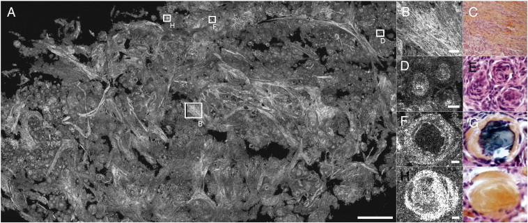
(A) Meningioma psammoma. (B–C) Collagen bundles, (D–E) whorls, (F–G) calcifications, and (H–I) collagen balls. (C, E, G and I) Hemalun and phloxin stainings. Rectangles indicate locations of zooms. Scale bars show 500 μm (A), 50 μm (B, C), and 10 μm (D, E, F, G, H, I).
Mesenchymal non-meningothelial tumors such as hemangiopericytomas represent a classic differential diagnosis of meningiomas. In FF-OCT, the hemangiopericytoma is more monotonous in appearance than the meningiomas, with a highly vascular branching component with staghorn-type vessels (Fig. 6A, C).
Fig. 6.

Hemangiopericytoma. (A–B) Collagen network and branching vascular space.
Staghorn sinusoids appear white. (C–D) Vessel. (B and D) Hemalun and phloxin stainings. Scale bars show 250 μm.
3.3. FF-OCT images identify choroid plexus papilloma
The choroid plexus papilloma appears as an irregular coalescence of multiple papillas composed of elongated fibrovascular axes covered by a single layer of choroid glial cells (Fig. 7). By zooming in on an edematous papilla, the axis appears as a black structure covered by a regular light gray line (Fig. 7B). If the papilla central axis is hemorrhagic, the fine regular single layer is not distinguishable (Fig. 7C). Additional digital zooming in on the image reveals cellular level information, and some nuclei of plexus choroid cells can be recognized. However, cellular atypia and mitosis are not visible. These represent key diagnosis criteria used to differentiate choroid plexus papilloma (grade I) from atypical plexus papilloma (grade II).
Fig. 7.

(A) Papilloma — cauliflower-like aspect. (B–E) Empty papilla, (C–D) blood filled papilla, and (D–G) single layer of plexus cells. (E, F and G) Hemalun and phloxin stainings. Rectangles indicate locations of zooms. Scale bars show 150 μm (A), 50 μm (B, C, E, F), 20 μm (D, G).
3.4. FF-OCT images detect the brain tissue architecture modifications generated by diffusely infiltrative gliomas
Contrary to the choroid plexus papillomas which have a very distinctive architecture in histology (cauliflower-like aspect), very easily recognized in the FF-OCT images (Fig. 7A to G), diffusely infiltrating glioma does not present a specific tumor architecture (Fig. 8) as they diffusely permeate the normal brain architecture. Hence, the tumorous glial cells are largely dispersed through a nearly normal brain parenchyma (Fig. 8E). The presence of infiltrating tumorous glial cells attested by high magnification histological observation (irregular atypical cell nuclei compared to normal oligodendrocytes) is not detectable with the current generation of FF-OCT devices, as FF-OCT cannot reliably distinguish the individual cell nuclei due to lack of contrast (as opposed to lack of resolution). In our experience, diffuse low-grade gliomas (less than 20% of tumor cell density) are mistaken for normal brain tissue on FF-OCT images. However, in high-grade gliomas (Fig. 8G–K), the infiltration of the tumor has occurred to such an extent that the normal parenchyma architecture is lost. This architectural change is easily observed in FF-OCT and is successfully identified as high-grade glioma, even though the individual glial cell nuclei are not distinguished.
Fig. 8.

Glioma. Three different cases are shown here (A–B; C–F; G–L). (A–B) Microcysts (arrows) in an oligo-astrocytoma grade 2; (C–D) microcystic areas and Virchow–Robin space (arrows) in an astrocytoma grade 2; (E–F) enlarged Virchow–Robin spaces in an astrocytoma grade 2; (G–H) microvessels (arrow) and tumorous glial cells in an oligo-astrocytoma grade 3; and (I–J) pseudo-palisading necrosis in an oligo-astrocytoma grade 3. Necrosis appears as dark diamond shaped area. White powdery substance in center of dark space (white arrow) is lysed cells (necrotic cells/centers). Dark arrow on histology shows a vessel. (K–L) Vasculature (arrows) in an oligo-astrocytoma grade 3 is immediately visible in white in FF-OCT images, while in histology an additional coloration is required to visualize this feature. (B, D, F, H and J) Hemalun and phloxin stainings and CD34 immunostaining (L). Scale bars show 250 μm (A, B), 100 μm (C–F), 20 μm (G, H), and 10 μm (I–L).
4. Discussion
We present here the first large size images (i.e. on the order of 1–3 cm2) acquired using an OCT system that offer spatial resolution comparable to histological analysis, sufficient to distinguish microstructures of the human brain parenchyma.
Firstly, the FF-OCT technique and the images presented here combine several practical advantages. The imaging system is compact, it can be placed in the operating room, the tissue sample does not require preparation and image acquisition is rapid. This technique thus appears promising as an intraoperative tool to help neurosurgeons and pathologists.
Secondly, resolution is sufficient (on the order of 1 μm axial and lateral) to distinguish brain tissue microstructures. Indeed, it was possible to distinguish neuron cell bodies in the cortex and axon bundles going towards white matter. Individual myelin fibers of 1 μm in diameter are visible on the FF-OCT images. Thus FF-OCT may serve as a real-time anatomical locator.
Histological architectural characteristics of meningothelial, fibrous, transitional and psammomatous meningiomas were easily recognizable on the FF-OCT images (lobules and whorl formation, collagenous-septae, calcified psammoma bodies, thick vessels). Psammomatous and transitional meningiomas presented distinct architectural characteristics in FF-OCT images in comparison to those observed in hemangiopericytoma. Thus, FF-OCT may serve as an intraoperative tool, in addition to extemporaneous examination, to refine differential diagnosis between pathological entities with different prognoses and surgical managements.
Diffuse glioma was essentially recognized by the loss of normal parenchyma architecture. However, glioma could be detected on FF-OCT images only if the glial cell density is greater than around 20% (i.e. the point at which the effect on the architecture becomes noticeable). The FF-OCT technique is therefore not currently suitable for the evaluation of low tumorous infiltration or tumorous margins. Evaluation at the individual tumor cell level is only possible by IDH1R132 immunostaining in IDH1 mutated gliomas in adults (Preusser et al., 2011). One of the current limitations of the FF-OCT technique for use in diagnosis is the difficulty in estimating the nuclear/cytoplasmic boundaries and the size and form of nuclei as well as the nuclear-cytoplasmic ratio of cells. This prevents precise classification into tumor subtypes and grades.
To increase the accuracy of diagnosis of tumors where cell density measurement is necessary for grading, perspectives for the technique include development of a multimodal system (Harms et al., 2012) to allow simultaneous co-localized acquisition of FF-OCT and fluorescence images. The fluorescence channel images in this multimodal system show cell nuclei, which increase the possibility of diagnosis and tumor grading direct from optical images. However, the use of contrast agents for the fluorescence channel means that the multimodal imaging technique is no longer non-invasive, and this may be undesirable if the tissue is to progress to histology following optical imaging. This is a similar concern in confocal microscopy where use of dyes is necessary for fluorescence detection (Wirth et al., 2012).
In its current form therefore, FF-OCT is not intended to serve as a diagnostic tool, but should rather be considered as an additional intraoperative aid in order to determine in a short time whether or not there is suspicious tissue present in a sample. It does not aim to replace histological analyses but rather to complement them, by offering a tool at the intermediary stage of intraoperative tissue selection. In a few minutes, an image is produced that allows the surgeon or the pathologist to assess the content of the tissue sample. The selected tissue, once imaged with FF-OCT, may then proceed to conventional histology processing in order to obtain the full diagnosis (Assayag et al., 2013; Dalimier and Salomon, 2012).
Development of FF-OCT to allow in vivo imaging is underway, and first steps include increasing camera acquisition speed. First results of in vivo rat brain imaging have been achieved with an FF-OCT prototype setup, and show real-time visualization of myelin fibers (Ben Arous et al., 2011) and movement of red blood cells in vessels (Binding et al., 2011). To respond more precisely to surgical needs, it would be preferable to integrate the FF-OCT system into a surgical probe. Work in this direction is currently underway and preliminary images of skin and breast tissue have been captured with a rigid probe FF-OCT prototype (Latrive and Boccara, 2011).
In conclusion, we have demonstrated the capacity of FF-OCT for imaging of human brain samples. This technique has potential as an intraoperative tool for determining tissue architecture and content in a few minutes. The 1 μm3 resolution and wide-field down to cellular-level views offered by the technique allowed identification of features of non-tumorous and tumorous tissues such as myelin fibers, neurons, microcalcifications, tumor cells, microcysts, and blood vessels. Correspondence with histological slides was good, indicating suitability of the technique for use in clinical practice for tissue selection for biobanking for example. Future work to extend the technique to in vivo imaging by rigid probe endoscopy is underway.
The following are the supplementary data related to this article.
Shows a movie composed of a series of en face 1 μm thick optical slices captured over 100 μm into the depth of the cortex tissue. The myelin fibers and neuronal cell bodies are seen in successive layers. Field size is 800 μm × 800 μm.
Shows a fly-through movie in the reconstructed cross-sectional orientation showing 1 μm steps through a 3D stack down to 200 μm depth in cerebellum cortical tissue. Purkinje and granular neurons are visible as dark spaces. Field size is 800 μm × 200 μm.
Supplementary data to this article can be found online at http://dx.doi.org/10.1016/j.nicl.2013.04.005.
Acknowledgments
The authors wish to thank LLTech SAS for use of the LightCT Scanner.
Footnotes
This is an open-access article distributed under the terms of the Creative Commons Attribution-NonCommercial-ShareAlike License, which permits non-commercial use, distribution, and reproduction in any medium, provided the original author and source are credited.
References
- Adie, Boppart . SpringerLink; 2009. Optical Coherence Tomography for Cancer Detection; pp. 209–250. [Google Scholar]
- Assayag Large field, high resolution full field optical coherence tomography: a pre-clinical study of human breast tissue and cancer assessment. Technology in Cancer Research & Treatment TCRT Express. 2013;1(1):e600254. doi: 10.7785/tcrtexpress.2013.600254. [DOI] [PMC free article] [PubMed] [Google Scholar]
- Beck Computer-assisted visualizations of neural networks: expanding the field of view using seamless confocal montaging. Journal of Neuroscience Methods. 2000;98(2):155–163. doi: 10.1016/s0165-0270(00)00200-4. [DOI] [PubMed] [Google Scholar]
- Ben Arous Single myelin fiber imaging in living rodents without labeling by deep optical coherence microscopy. Journal of Biomedical Optics. 2011;16(11):116012. doi: 10.1117/1.3650770. [DOI] [PubMed] [Google Scholar]
- Betz C.S. A set of optical techniques for improving the diagnosis of early upper aerodigestive tract cancer. Medical Laser Application. 2008;23:175–185. [Google Scholar]
- Binding Brain refractive index measured in vivo with high-NA defocus-corrected full-field OCT and consequences for two-photon microscopy. Optics Express. 2011;19(6):4833–4847. doi: 10.1364/OE.19.004833. [DOI] [PubMed] [Google Scholar]
- Bizheva Imaging ex vivo healthy and pathological human brain tissue with ultra-high-resolution optical coherence tomography. Journal of Biomedical Optics. 2005;10:011006. doi: 10.1117/1.1851513. [DOI] [PubMed] [Google Scholar]
- Böhringer Time domain and spectral domain optical coherence tomography in the analysis of brain tumor tissue. Lasers in Surgery and Medicine. 2006;38:588–597. doi: 10.1002/lsm.20353. [DOI] [PubMed] [Google Scholar]
- Böhringer Imaging of human brain tumor tissue by near-infrared laser coherence tomography. Acta Neurochirurgica. 2009;151:507–517. doi: 10.1007/s00701-009-0248-y. [DOI] [PMC free article] [PubMed] [Google Scholar]
- Boppart Optical coherence tomography: technology and applications for neuroimaging. Psychophysiology. 2003;40:529–541. doi: 10.1111/1469-8986.00055. [DOI] [PubMed] [Google Scholar]
- Boppart Optical coherence tomography for neurosurgical imaging of human intracortical melanoma. Neurosurgery. 1998;43:834–841. doi: 10.1097/00006123-199810000-00068. [DOI] [PubMed] [Google Scholar]
- Boppart Optical coherence tomography: feasibility for basic research and image-guided surgery of breast cancer. Breast Cancer Research and Treatment. 2004;84:85–97. doi: 10.1023/B:BREA.0000018401.13609.54. [DOI] [PubMed] [Google Scholar]
- Chen Ultrahigh resolution optical coherence tomography of Barrett's esophagus: preliminary descriptive clinical study correlating images with histology. Endoscopy. 2007;39:599–605. doi: 10.1055/s-2007-966648. [DOI] [PubMed] [Google Scholar]
- Dalimier, Salomon Full-field optical coherence tomography: a new technology for 3D high-resolution skin imaging. Dermatology. 2012;224:84–92. doi: 10.1159/000337423. [DOI] [PubMed] [Google Scholar]
- De Boer Improved signal-to-noise ratio in spectral-domain compared with time-domain optical coherence tomography. Optics Letters. 2003;28:2067–2069. doi: 10.1364/ol.28.002067. [DOI] [PubMed] [Google Scholar]
- Dubois High-resolution full-field optical coherence tomography with a Linnik microscope. Applied Optics. 2002;41(4):805. doi: 10.1364/ao.41.000805. [DOI] [PubMed] [Google Scholar]
- Dubois Ultrahigh-resolution full-field optical coherence tomography. Applied Optics. 2004;43(14):2874. doi: 10.1364/ao.43.002874. [DOI] [PubMed] [Google Scholar]
- Grieve Ocular tissue imaging using ultrahigh-resolution, full-field optical coherence tomography. Investigative Ophthalmology & Visual Science. 2004;45:4126-3–4131. doi: 10.1167/iovs.04-0584. [DOI] [PubMed] [Google Scholar]
- Harms . Proc. SPIE 2011. Vol. 8216. 2012. Multimodal full-field optical coherence tomography on biological tissue: toward all optical digital pathology. (Multimodal Biomedical Imaging VII). [Google Scholar]
- Hsiung Benign and malignant lesions in the human breast depicted with ultrahigh resolution and three-dimensional optical coherence tomography. Radiology. 2007;244:865–874. doi: 10.1148/radiol.2443061536. [DOI] [PubMed] [Google Scholar]
- Huang Optical coherence tomography. Science. 1991;254(5035):1178–1181. doi: 10.1126/science.1957169. [DOI] [PMC free article] [PubMed] [Google Scholar]
- INCa (Institut National du Cancer) Technical Report: La situation du cancer en France. 2011. (Boulogne —Billancourt) [Google Scholar]
- Kelly Magnetic resonance imaging-based computer-assisted stereotactic resection of the hippocampus and amygdala in patients with temporal lobe epilepsy. Mayo Clinic Proceedings. 1987;62(2):103–108. doi: 10.1016/s0025-6196(12)61877-1. [DOI] [PubMed] [Google Scholar]
- Latrive, Boccara Full-field optical coherence tomography with a rigid endoscopic probe. Biomedical Optics Express. 2011;2(10):2897–2904. doi: 10.1364/BOE.2.002897. [DOI] [PMC free article] [PubMed] [Google Scholar]
- Leitgeb Performance of Fourier domain vs. time domain optical coherence tomography. Optics Express. 2003;11:889–894. doi: 10.1364/oe.11.000889. [DOI] [PubMed] [Google Scholar]
- Luo Optical biopsy of lymph node morphology using optical coherence tomography. Technology in Cancer Research & Treatment. 2005;4:539–548. doi: 10.1177/153303460500400507. [DOI] [PubMed] [Google Scholar]
- Nguyen Intraoperative evaluation of breast tumor margins with optical coherence tomography. Cancer Research. 2009;69:22. doi: 10.1158/0008-5472.CAN-08-4340. [DOI] [PMC free article] [PubMed] [Google Scholar]
- Ozawa In vivo imaging of human labial glands using advanced optical coherence tomography. Oral Surgery, Oral Medicine, Oral Pathology, Oral Radiology, and Endodontology. 2009;108:425–429. doi: 10.1016/j.tripleo.2009.05.035. [DOI] [PubMed] [Google Scholar]
- Preusser Value and limitations of immunohistochemistry and gene sequencing for detection of the IDH1-R132H mutation in diffuse glioma biopsy specimens. Journal of Neuropathology and Experimental Neurology. 2011;70(8):715–723. doi: 10.1097/NEN.0b013e31822713f0. [DOI] [PubMed] [Google Scholar]
- Rigau French brain tumor database: 5-year histological results on 25 756 cases. Brain Pathology. 2011;21:633–644. doi: 10.1111/j.1750-3639.2011.00491.x. [DOI] [PMC free article] [PubMed] [Google Scholar]
- Sanai Functional outcome after language mapping for glioma resection. The New England Journal of Medicine. 2008;358:18–27. doi: 10.1056/NEJMoa067819. [DOI] [PubMed] [Google Scholar]
- Sanai Intraoperative confocal microscopy for brain tumors: a feasibility analysis in humans. Neurosurgery. 2011;68:282–290. doi: 10.1227/NEU.0b013e318212464e. [DOI] [PubMed] [Google Scholar]
- Soffietti Guidelines on management of low-grade gliomas: report of an EFNS–EANO Task Force. European Journal of Neurology. 2010;17:1124–1133. doi: 10.1111/j.1468-1331.2010.03151.x. [DOI] [PubMed] [Google Scholar]
- Srinivasan Optical coherence microscopy for deep tissue imaging of the cerebral cortex with intrinsic contrast. Optics Express. 2012;20:2220–2239. doi: 10.1364/OE.20.002220. [DOI] [PMC free article] [PubMed] [Google Scholar]
- Stummer Fluorescence-guided resection of glioblastoma multiforme utilizing 5-ALA-induced porphyrins: a prospective study in 52 consecutive patients. Journal of Neurosurgery. 2000;93(6):1003–1013. doi: 10.3171/jns.2000.93.6.1003. [DOI] [PubMed] [Google Scholar]
- Swanson In vivo retinal imaging by optical coherence tomography. Optics Letters. 1993;18(21):1864–1866. doi: 10.1364/ol.18.001864. [DOI] [PubMed] [Google Scholar]
- Tearney Optical biopsy in human pancreatobiliary tissue using optical coherence tomography. Digestive Diseases and Sciences. 1998;43:1193–1199. doi: 10.1023/a:1018891304453. [DOI] [PubMed] [Google Scholar]
- Wirth Identifying brain neoplasms using dye-enhanced multimodal confocal imaging. Journal of Biomedical Optics. 2012;17(2):026012. doi: 10.1117/1.JBO.17.2.026012. [DOI] [PubMed] [Google Scholar]
- Wojtkowski In vivo human retinal imaging by Fourier domain optical coherence tomography. Journal of Biomedical Optics. 2002;7:457–463. doi: 10.1117/1.1482379. [DOI] [PubMed] [Google Scholar]
- Zhou Integrated optical coherence tomography and microscopy for ex vivo multiscale evaluation of human breast tissues. Cancer Research. 2010;70:10071–10079. doi: 10.1158/0008-5472.CAN-10-2968. [DOI] [PMC free article] [PubMed] [Google Scholar]
- Zysk, Boppart Computational methods for analysis of human breast tumor tissue in optical coherence tomography images. Journal of Biomedical Optics. 2006;11(054015):1–7. doi: 10.1117/1.2358964. [DOI] [PubMed] [Google Scholar]
Associated Data
This section collects any data citations, data availability statements, or supplementary materials included in this article.
Supplementary Materials
Shows a movie composed of a series of en face 1 μm thick optical slices captured over 100 μm into the depth of the cortex tissue. The myelin fibers and neuronal cell bodies are seen in successive layers. Field size is 800 μm × 800 μm.
Shows a fly-through movie in the reconstructed cross-sectional orientation showing 1 μm steps through a 3D stack down to 200 μm depth in cerebellum cortical tissue. Purkinje and granular neurons are visible as dark spaces. Field size is 800 μm × 200 μm.