. 2013 Sep 17;2:e00951. doi: 10.7554/eLife.00951

Figure 2. Structure of the outer COPII coat.

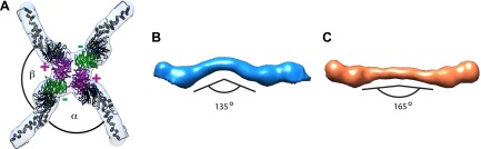
(A) Isosurface representation of the outer coat vertex solved by sub-tomogram averaging of tubular membranes. ‘+’ and ‘−’ ends of Sec13/31 and alpha and beta angles are as defined by (Stagg et al., 2008) (Figure 2—figure supplement 2 and panel D). (B) Structures of the rods that interconnect neighbouring vertices in left-handed (green) and right-handed (purple) helical directions, viewed from the top (upper panels), and the side (lower panels). Left-handed rods have two ‘−’ ends, whereas right-handed rods have two ‘+’ ends. (C) Atomic model of the Sec13/31 complex (Fath et al., 2007) (PDB 2PM9 and 2PM6) fitted as a rigid body into left- and right-handed rods. (D) Isosurface representation of the Sec13/31 vertex structure from cryo-electron microscopy of in vitro assembled cuboctahedral cages (Stagg et al., 2006) (EMDB ID 1232). (E) Structure of the rods segmented from in vitro assembled cuboctahedral cages (Stagg et al., 2006) (EMDB ID 1232) for comparison. ‘+’ and ‘−’ ends are coloured purple and green respectively. (F) The Sec13/31 complex fitted into a rod from the cuboctahedral cage. To adapt to the 45° bend in the rod two equivalent heterodimers were fitted independently.

DOI: http://dx.doi.org/10.7554/eLife.00951.004

Figure 2.

Figure 2—figure supplement 1. Resolution of outer coat structures.

Figure 2—figure supplement 1.

The resolution of the sub-tomogram averaged structures of outer coat (blue = vertices, purple = right-handed rods, green = left-handed rods) were estimated by Fourier Shell Correlation (see ‘Materials and methods’ for details). Resolution at the 0.5 threshold criterion is indicated.
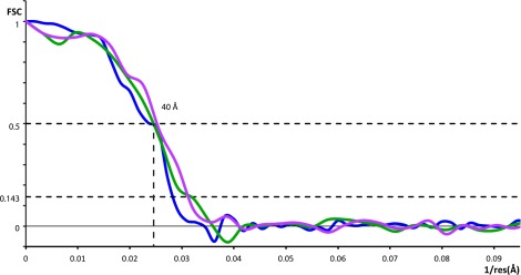
Figure 2—figure supplement 2. Previously published outer coat structures.

Figure 2—figure supplement 2.

(A) A close up view of the vertex in the cuboctahedral cage (Stagg et al., 2006), with the X-ray model for Sec13/31 dimers fitted into the half-rods. The vertex forms upon interaction of four N-terminal Sec31 β-propellers. The β-propellers on two heterotetramer rods (purple) face each other at the center of the vertex and are referred to as the ‘plus’ ends of the rods, while the β-propellers on the other two rods (green) are further away from the center, and are referred to as the ‘minus’ ends. In the cuboctahedral and icosidodecahedral cage geometries, each rod has a plus and a minus end. When viewing the vertex from outside the cage, alpha is defined as the clockwise angle from ‘+’ to ‘−’, and beta the clockwise angle from ‘−’ to ‘+’. These interactions allow assembly of a coat that curves in two directions, appropriate for coating spherical membranes. (B) A close up view of the rod segmented from the edge of the cuboctahedral cage. The rod is bent in the middle at the Sec31 dimerisation interface by an angle of 135°. (C) A surface representation of the atomic structure of the Sec13/31 heterodimer as solved by X-ray crystallography (Fath et al., 2007), filtered to a resolution of 40 Å. The structure is overall very similar to the cuboctahedral cage edge, but the bend in the middle of the rod is less accentuated, with an angle of 165°.