Abstract
Understanding the compatibility between spider silk and conducting materials is essential to advance the use of spider silk in electronic applications. Spider silk is tough, but becomes soft when exposed to water. Here we report a strong affinity of amine-functionalised multi-walled carbon nanotubes for spider silk, with coating assisted by a water and mechanical shear method. The nanotubes adhere uniformly and bond to the silk fibre surface to produce tough, custom-shaped, flexible and electrically conducting fibres after drying and contraction. The conductivity of coated silk fibres is reversibly sensitive to strain and humidity, leading to proof-of-concept sensor and actuator demonstrations.
 The use of spider silk in electronic devices is dependent on its compatibility with electrically conductive materials. Here the authors modify spider silk with carbon nanotubes to produce a strong, flexible and electrically conductive thread.
The immense demand for electronics, and thus the electronic waste and environmental pollution it generates, poses a growing problem that will require innovative solutions1. Many toxic elements and non-biodegradable plastics are commonly found in conventional electronics, and efforts to develop new eco-friendly electronic designs are therefore desirable. Incorporation of natural materials into these designs is advantageous to reduce the quantity of toxic components of the electronic devices. Moreover, natural materials often possess complex and robust physical properties that can be harnessed for electrical and sensor applications. Spider silk (SS) is one such material and the combination of its toughness2 and bio-compatibility3,4 makes the material strategically important for implant, electrical, sensor and actuating applications.
SS, a protein-based natural polymer, is a flexible but strong material due to its helical-elastic and β-sheet crystalline composition5,6. An unrestrained neat SS fibre expands in both length and diameter7,8 when humidified up to ~70 or 80% relative humidity (RH). At higher RH, the fibre experiences supercontraction7,8,9,10, where it shrinks in length, expands in diameter and becomes soft. This fibre shrinkage is typically an irreversible process11. The fibre softening, however, is a reversible process12. In addition, the fibre also experiences cyclic contraction11, a phenomenon different from supercontraction, where the fibre extends when exposed to a high-humidity environment. These factors are key to the work presented here.
For technological applications, where constant strength and flexibility in a variable environment are desired, supercontraction may be regarded as a problem. However, both supercontraction and cyclic contraction can be exploited for actuating applications. For example, it has been shown that SS fibres can be used as a biomimetic muscle with an exceptional work density, 50 times higher than other biological muscle fibres, estimated to be capable of lifting a 5 kg mass with a 1mm thick SS fibre11. SS fibres can also be used as contact13 or shadow14 masks during thin film deposition, generating micro-13 or nano patterned14 features without lithographic processing. Moreover, starting from its intrinsic properties, SS fibres can serve as a versatile scaffold upon which additional functions can be built. For example, CdTe15, magnetite16 and gold16,17 nanoparticles can be used to functionalise SS for fluorescent, magnetic and electronic applications, respectively. Gold-functionalised fibres (Au-SS) have been shown to be electrically robust down to cryogenic temperatures17. Even though Au-SS possesses sufficient flexibility for use as electrodes in microelectronics17, generally its elasticity and electrical continuity are not adequate for electronic sensors or actuating devices.
Here we show that supercontraction, and in particular, silk fibre softening, provides a simple and effective route of SS functionalisation with carbon nanotubes (CNTs), enabling use in electronic applications including sensors and actuating devices. We report a strong affinity for amine-functionalised multiwall CNTs (f-CNTs) to adhere to natural Nephila clavipes SS fibres. Adhesion is facilitated by water and mechanical shear, and enhanced by polar interactions and bonding between the SS and f-CNT side groups. The process results in SS fibres uniformly coated with f-CNTs (f-CNT-SS) providing an electrically conducting path, and thereby a self-monitoring mechanism for physical changes and/or stimuli to the f-CNT-SS structure. The f-CNT-SS fibres are ~300% tougher than neat silk fibre, versatile and multi-functional, and exhibit polar (Supplementary Movie 1), shapeable, conducting, flexible, strain- and humidity-sensitive properties. Proof-of-concept f-CNT-SS-based heart pulse sensor and current-driven actuator devices are demonstrated.
Results
Water-based f-CNT coating of SS fibres
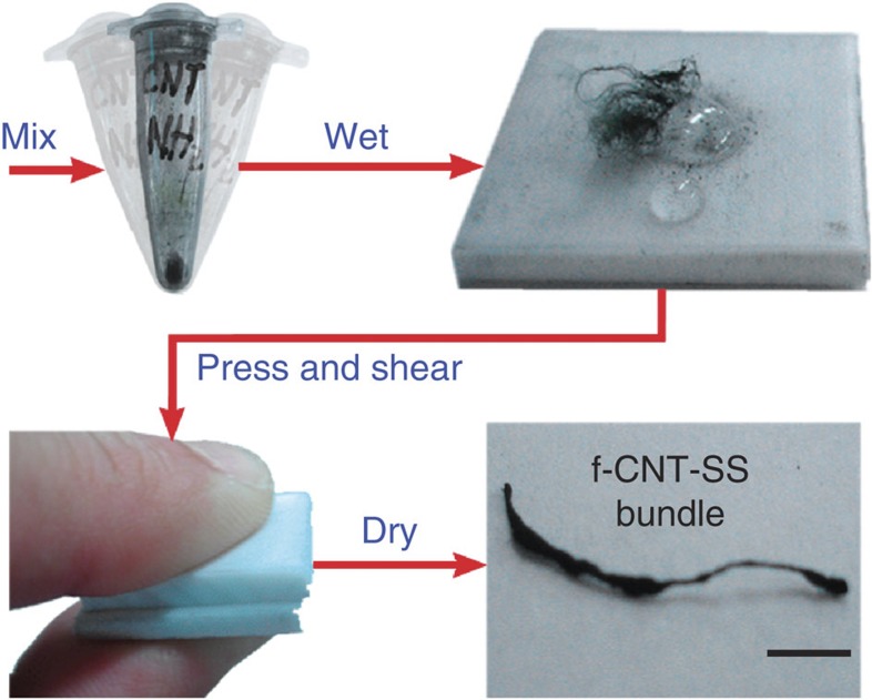
We discovered that by mixing a bundle of dragline SS fibres (~2 cm long) with a dry powder of f-CNTs (Methods section), applying a few drops of water, and then pressing and shearing the mixture between two Teflon (Polytetrafluoroethylene) sheets, the fibres turned very black, and when dried, contracted to a well-defined geometry where the silk fibres were uniformly coated with nanotubes (Fig. 1). The neat bundle contained multiple dragline silk fibres in their natural double-stranded arrangement (each strand has a diameter of ~4 μm), all of which were coated simultaneously. After the coating process, the dragline silk fibres were well separated into individually coated single-strand fibres (referred to as single fibres for the rest of the paper), accompanied by small isolated f-CNT aggregates (Supplementary Fig. S1).
Figure 1. f-CNT-SS processing steps.
A neat SS bundle is mixed with a dry f-CNT powder. The mixture is then wet, pressed, sheared between two PTFE substrates, and air dried. Scale bar: 2 mm.
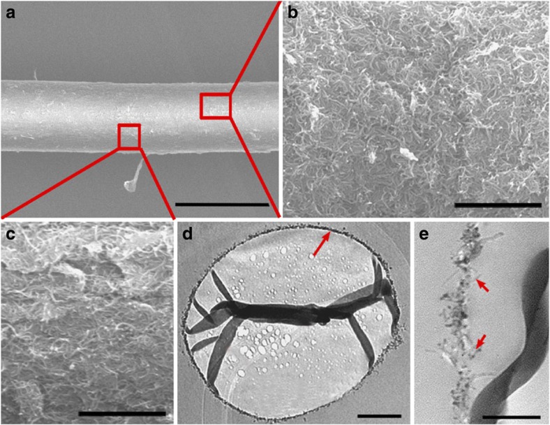
This separation allowed reliable extraction of single silk fibres from the bundle. SEM and TEM images of the single silk fibre show that the f-CNTs are attached to the SS structure (Fig. 2a–d), including some penetration of the nanotubes into the SS surface (Fig. 2e). This procedure produces a basic uniform annular f-CNT coating with thickness of ~80–100 nm with occasional f-CNT aggregates of ~1 μm in diameter and thickness (Supplementary Fig. S2). Additional SEM and TEM images of another silk fibre are available (Supplementary Figs S1 and S2).
Figure 2. Single f-CNT-SS fibre surface profiles.
(a) SEM image of f-CNT-SS. The diameter of the fibre is ~6.5 μm. Scale bar: 10 μm. (b,c) Magnified SEM images of f-CNT-SS surface showing a uniform mat-like covering. Scale bars: 1 μm. (d) TEM cross section of a dragline silk fibre with f-CNT coating (red arrow). Silk folding due to uneven sectioning. Scale bar: 1 μm. (e) TEM image indicating nanotube penetration (red arrows) into the silk structure. Scale bar: 250 nm.
We have also performed a control experiment involving pre-supercontracted fibres. The neat fibres are first immersed in a water bath for 30 min, followed by air drying, and then the water-based f-CNT coating is performed. The water-based procedure is also effective on these pre-supercontracted fibres, indicating that the initial shrinkage of silk fibre is not the most important factor to achieve the effective coating, but it is the softening of the fibre during supercontraction.
We note that a dry powder of pure multiwall CNTs (MWCNTs) does not provide effective initial dispersion and adhesion to the SS fibre (Supplementary Fig. S3). As a result, it is not possible to coat the SS fibre with pure MWCNTs using our water-based method. Likewise, only SS fibres exhibit an effective f-CNT coating compared with nylon, polyester, cotton and some acrylic fibres where either spotty or no coating was observed. Unlike water, other solvents such as hexane, toluene, methanol, ethanol, acetone, dichloromethane and dimethylsulphoxide do not facilitate a uniform coating.
Fourier transform infrared spectroscopy
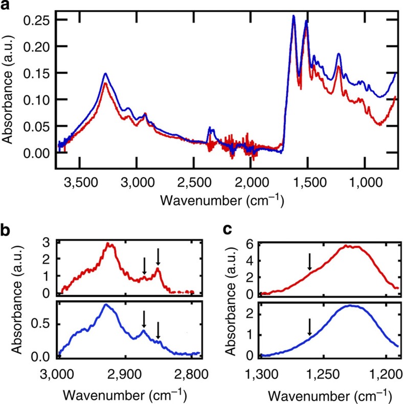
To examine more closely the nature of the f-CNT/SS interface, and in particular the interaction between the NH2 side group of the f-CNTs and SS protein structure, Fourier transform infrared (FTIR) spectroscopy is employed. The overall FTIR spectra of both the neat SS and f-CNT-SS are similar (Fig. 3a), showing almost identical features in the amide I (1,700–1,600 cm−1) and amide II (1,500–1,400 cm−1) region18,19. As the absorption in amide I and amide II regions is sensitive only to the secondary structure of the SS fibres19, this indicates that there are no major secondary structure transformations after the f-CNT coating; therefore, the β-sheet and coil composition in the SS protein structures remain the same.
Figure 3. FTIR spectra of neat and f-CNT-SS fibres.
(a) Combined FTIR spectra normalised to the amide I peak at 1,625 cm−1 (red: neat fibres, blue: f-CNT-SS). (b) Expanded view of the spectra between 3,000 and 2,800 cm−1. Arrows indicate the position of the peaks of interest. (c) Expanded view of the spectra near amide III region. A subtle reduction in the peak intensity near 1,260 cm−1 is observed after f-CNT coating.
However, a distinct feature in the amide III (1,350–1,200 cm−1) region18,19 is observed. Contrary to the amide I and II regions, the absorption in the amide III region is sensitive to the structure of amino acid side-chains19. In Fig. 3c, a peak intensity reduction is observed for the absorption corresponding to the O-H bond of aspartic and glutamic acid (1,254 cm−1)19, indicating transformations of a fraction of the acid hydroxyl groups. The content of O-H groups subjected to the transformations is extracted from deconvolution of the bands, as shown in Supplementary Fig. S4. The reduction is very subtle (Supplementary Fig. S5), as expected, due to the low abundance of aspartic and glutamic acids in SS fibres (maximum abundance of ~0.6 and ~8.8%, respectively)20. Additional evidence for chemical interactions is revealed by the change in the C-H symmetric stretching absorption profile observed in 2,900–2,800 cm−1 region (Fig. 3b), where the peak intensities at 2,851 (CH2 stretch) and 2,872 cm−1 (CH3 stretch) are reduced and increased, respectively, after the CNT coating21,22. How the acid hydroxyl group transformation affects the C-H stretching absorption is not yet understood. As a control, we have also compared the FTIR spectra of neat fibres with fibres that have been subjected to water, shear and pressure without the f-CNTs. We confirm that no observable difference in the FTIR spectrum is observed after the treatment (Supplementary Fig. S5).
Raman spectroscopy
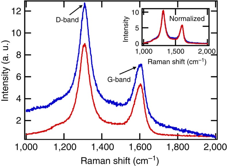
Raman spectroscopy has been used to evaluate the effects of the water-based method on the properties of the f-CNTs being used. In Fig. 4, the Raman spectrum of a single f-CNT-SS fibre is compared with the spectrum of a dry powder of the f-CNT control sample. Owing to the thin f-CNT coating, a weak background signal that comes from the SS fibre (Supplementary Fig. S6) is observed in the spectrum. Except for the partial contribution of the background signal, both the f-CNT-SS fibre and the control sample exhibit similar D-band (~1,300 cm−1) and G-band (~1,600 cm−1) peaks, which are associated with disordered and graphitized carbon, respectively. With the SS background subtracted, the normalized spectrum of f-CNT-SS is almost identical to that of the control (inset of Fig. 4), including the D-band/G-band peak intensity ratio, indicating that no additional disorder is introduced during the coating process. The uniformity of the f-CNT coating is confirmed by the similarity of the Raman spectra for three random areas of the same fibre (Supplementary Fig. S6).
Figure 4. Raman spectra of f-CNT-SS fibre and dry f-CNT powder.
The f-CNT-SS spectrum has been offset to show the linear background contribution more clearly (blue: f-CNT-SS fibre, red: dry f-CNT powder). Inset shows background-subtracted and normalized spectrum of f-CNT-SS, showing an overlap with the spectrum of the control sample.
Tensile properties
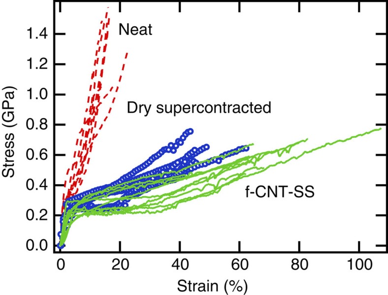
The strength of the f-CNT-SS fibre (~0.6 GPa) is lower than that of a neat fibre (~1.4 GPa), but is very similar to the strength of the supercontracted dry fibre (~0.6 GPa), as shown in Fig. 5. However, the f-CNT-SS fibre has a larger extensibility (defined as the maximum strain allowed before breaking) of ~73%, compared with that of the neat (~16%) and dry supercontracted (~47%) fibres. Therefore, the toughness (defined as the area under the stress–strain curve) of f-CNT-SS fibre is improved to ~290 MJ m−3, ~300% more than that of a neat fibre. A summary of the tensile properties of the fibres is presented in Supplementary Tables S1 and S2.
Figure 5. Tensile properties of neat and processed SS single fibres.
Measurement was performed at 25% RH to reduce the effects of water vapour absorption on the tensile properties (dashed lines: neat fibres, circles: dry supercontracted fibres, solid lines: f-CNT-SS fibres).
Electrical conductivity
The conductivity extracted from the resistance of a single f-CNT-SS is in the range of 12–15 S cm−1 (see Methods for calculation details). This value is consistent with that of a buckypaper control sample (~13 S cm−1) made using the same f-CNT powder with benzoquinone cross-linkers following the procedure described in the study by Ventura et al.23 The single f-CNT-SS conductivity value is also consistent with the reported value24 for MWCNT array samples of 7–14 S cm−1.
Custom shaped f-CNT-SS
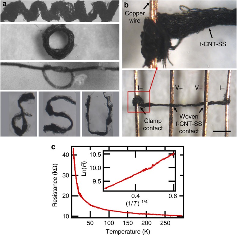
As shown in Fig. 6a, it is possible to shape the f-CNT-SS into various forms while it remains conducting. The f-CNT-SS is first wet using de-ionized water and bent into the desired shape. After drying, the f-CNT-SS shape is maintained and the conductivity stays within 20% of its original value. This process can be repeated to obtain other shapes with similar conducting properties. The softness of f-CNT-SS while in the wet state may mitigate the formation of CNT cracks during the bending process.
Figure 6. Custom-shaped f-CNT-SS for clamped and woven electrodes.
(a) Photographs of f-CNT-SS shaped into coil, ring, knotted and letter forms. (b) Photograph of clamped (I±) and woven (V±) contacts used to characterize the temperature-dependent resistance of f-CNT-SS with clamp I+ contact expansion. Scale bar: 500 μm. (c) VRH nature (that is, ln(R)~(1/T)1/4) of f-CNT-SS.
Temperature-dependent resistance
The shapeable property of f-CNT-SS allows us to make clamped or woven electrode configurations for electrical measurements. Electrodes can be made by wetting the f-CNT-SS fibres, and then winding and weaving them onto a four-terminal copper wire resistance circuit (Fig. 6b). After drying, the fibres contract, squeezing the outer two copper wires (current leads) and increasing the tension between the inner two copper wires (voltage leads). The contracted f-CNT-SS/copper electrical contacts are robust in ambient or vacuum environment down to cryogenic temperatures. The resistance (R) follows a three-dimensional (3D) variable range hopping (VRH)25 behaviour R=R0 exp ([T0/T]1/4) down to ~4.3 K (Fig. 6c), with a barrier energy T0~108 K, consistent with that of a pressed pure-MWCNT pellet reported in the literature26. This behaviour is compared with that of a buckypaper control sample (Supplementary Fig. S7). At higher temperature, T>30 K, the buckypaper follows a 3D VRH behaviour with T0~53 K, comparable with the case of the f-CNT-SS. However, at <30 K, the buckypaper exhibits one-dimensional (1D) VRH behaviour, for example: R=R0 exp ([T0/T]1/2).
Strain-dependent resistance
Under a strain Δl/l of up to at least 50% (Fig. 7a), a single f-CNT-SS fibre remains conducting, and the f-CNT coating can expand and contract in unison with the SS fibre, thereby maintaining an electrical linkage without crossing a percolation threshold. In some cases, it is possible to obtain fibres that in the dry state under ambient conditions can be stretched up to 200% of the initial length while remaining conducting (Supplementary Movie 2; a bundle of fibres was used in the video for clear visualization). With a gauge factor (ΔR/R)/(Δl/l)=1.2±0.02 (Fig. 7b), this leads immediately to proof-of-concept applications such as strain-sensitive resistive sensors for heart-pulse monitoring (Fig. 7c). The f-CNT coating also provides electrical readout to monitor strain changes due to humidity variation (Fig. 7d). We note that for a thicker f-CNT or gold coating, no humidity response was observed.
Figure 7. Strain-dependent resistance of f-CNT-SS.
(a) Strain-dependent resistance of a single f-CNT-SS fibre up to 50% strain. (b) Cyclic strain test of a single fibre with a 1.2 gauge factor (red line: resistance, blue line: strain). (c) Demonstration of the strain sensitive resistance of f-CNT-SS to heart pulses. A bundle of f-CNT-SS with R~11 kΩ was used in this device. Left and right scale bars correspond to 1 cm and 1 mm, respectively. (d) Cyclic RH test up to 70% RH of a 2 × 2 mm2 f-CNT-SS mat with R~100 Ω (red line: ΔR, blue line: RH).
f-CNT-SS annealing and actuator function
We observed that an application of 100 μA current with a 40-s duration permanently reduced the resistance of f-CNT-SS by ~15% (Supplementary Fig. S8). The result was confirmed on three separate f-CNT-SS fibres. A systematic decrease in post-annealed resistance was observed up to 150 μA.
By using the f-CNT coating as a local heating element, it was possible to utilize a single f-CNT-SS fibre as a current-driven actuator (Fig. 8). The actuator could be operated in two modes. First, the contraction mode (Fig. 8b) was achieved by applying a 100-μA current to a single f-CNT-SS fibre in its natural partially hydrated state under ambient conditions (55% RH, 23 °C). The local heat (~5 mW) generated by a 100-μA current dehydrated the fibre, therefore contracting the fibre by ~1% of its original length (1.8 mm). Consequently, the mass (35 mg) was lifted by ~25 μm (Fig. 8b). The lifting action occurred almost instantaneously (≤1 s). After ~5 min, the fibre relaxed close to its original length due to rehydration. A longer time was required to fully rehydrate. The slow relaxation rate may be due to the vapour absorption rate intrinsic to the SS. Operation at lower temperature and/or higher RH may decrease the fibre relaxation time.
Figure 8. F-CNT-SS actuator activated by Joule heating.
(a) Photograph of a 35 mg mass hanging on a single f-CNT-SS fibre. Scale bar: 250 μm. (b) Cyclic f-CNT-SS contraction. The fibre was allowed to relax for 1 h before the next current cycle to ensure full rehydration. Scale bar: 150 μm.
In contrast with the contraction mode, the extension mode was achieved by applying a current after the initial dehydration. Here an application of current extended the fibre by ~0.15% of its dried length, lowering the mass by ~4 μm (Supplementary Movie 3). Furthermore, both the fibre extension and contraction actions occurred within 1 s. In principle, increasing the applied current would increase the extension length primarily due to thermal expansion. In both cases, we confirmed the repeatability of this behaviour for three different single f-CNT-SS fibres.
Discussion
The essential aspects leading to the realization of the f-CNT-SS material are as follows. The f-CNTs are polar, with positive charge at the amine sites. The SS is a protein-based polymer where the amino acid groups vary along the backbone, some are neutral and some polar27. By mechanical mixing, the dry f-CNT powder is partially dispersed and adheres to the SS fibres due to polar interaction (Supplementary Fig. S3). When water is applied to the mixture, the f-CNTs disperse further and the SS fibres experience hydrogen bond breaking8, resulting in fibre swelling and softening. As a result, the surface area of the fibre is increased, allowing more f-CNTs to adhere to the fibre. Applications of shear and pressure bring the f-CNTs in closer proximity to the surface of the fibre, promoting both physical and chemical interactions between them. Upon drying, the SS fibre matrix shrinks further as hydrogen bonding is re-established8,28, concentrating the CNT array and making it electrically conducting.
The FTIR spectra in Fig. 3 indicate a change in the nature of the SS carboxylic acids, consistent with the aqueous chemical reaction between the NH2 side groups of the f-CNT and the COOH component of aspartic and glutamic acids in the SS. As our water-based method is performed at room temperature, amide formation is unlikely because this type of reaction normally occurs at high temperatures22. However, ionic and hydrogen bonding are both likely to occur. In an aqueous solution, for example with pH of 4–7, some amount of side-chain carboxylic acids and amines are typically ionized. By applying shear and pressure, ionic bonding between them is promoted. In parallel, the NH2 side groups may form hydrogen bonding with the non-ionized aspartic and glutamic acids (Supplementary Fig. S9). The formation of hydrogen bonding at room temperature has been observed in the fabrication of buckypaper from O-H-functionalised CNTs29. Even though the f-CNT anchoring to the SS fibre is minimal due to the small abundance of aspartic and glutamic acids, it generates a significant grafting, such that when combined with the van der Waals interaction and the natural tendency of the f-CNTs to entangle, a new hybrid functional silk fibre is produced (Supplementary Fig. S9).
The intimate adherence of the f-CNTs on the SS fibre is the key factor that results in many of the observed phenomena such as the improved extensibility and toughness of the f-CNT-SS fibre. The toughness of f-CNT-SS fibres can be attributed first to the supercontraction that occurs during the coating process and second to the distribution of SS radial deformation by the f-CNT coating. SS fibres generally become tougher after being supercontracted. The release of internal pre-stress8 in neat SS fibres during supercontraction accounts for the additional energy they can absorb before rupturing. The f-CNT coating may further improve the toughness by effectively distributing the SS radial deformations associated with the rupture point during the extension process. A SS fibre experiences a very large radial deformation when strained longitudinally, with a Poisson ratio (a measure of how much the diameter of the fibre shrinks when the fibre is extended) of ~1.5 (ref. 30). In contrast, a CNT network, such as the buckypaper, experiences significantly less deformation (Poisson ratio up to 0.3), except in some special cases31. If intimately connected to the SS fibre, this can reduce the radial deformation of the silk fibre at the highest rupture point, for example, in the middle of the fibre, allowing further extension before it ruptures.
The uniformity of the f-CNT coating is demonstrated by the absence of sudden jumps in the resistance versus strain curve up to at least 50% strain (Fig. 5a). The uniform adherence strength between the f-CNT to SS and f-CNT to f-CNT contacts allows homogenous strain distribution during extension, similar to the mechanism observed in CNT-elastomer or gold-elastomer systems32,33, where extensions of >100 or 20% are observed, respectively. Additional flexibility may be provided by the fibre shrinkage during the water-based processing, which effectively concentrates the f-CNT network. We emphasize that no f-CNT crosslinkers are used in our water-based coating method. Without crosslinkers, it has been reported that the f-CNT network is typically very brittle23.
The 3D VRH transport of the f-CNT-SS reveals that the conductivity is dominated by inter-tube charge carrier hopping between the f-CNTs34, which may be related to the submicron length of the f-CNTs used (therefore resulting in a larger number of inter-tube contacts). The T0 and conductivity of the f-CNT-SS and the benzoquinone-crosslinked buckypaper are similar. This suggests that the simple water-based coating method is effective. The slightly higher T0 could mean that the f-CNTs were not as tightly entangled as in the case of crosslinked buckypaper, resulting in a slightly higher contact resistance between the f-CNTs.
The application of an annealing current under ambient conditions indicates a reduction in the contact resistance of the f-CNT network. A similar effect is observed in carbon nanofibre (CNF)–gold interconnects, where the application of an annealing current at ambient condition reduces the contact resistance between the CNF–gold interconnects35. As the f-CNT coating on the SS surface is very thin, ~80–100 nm, a 100-μA annealing current may generate a considerable current density that heats the CNT–CNT joints, producing better contacts.
Owing to the thin, flexible and porous nature of the f-CNT network, external stimuli such as varying strain and humidity levels will affect the SS fibre. We emphasize that for gold-coated (~20-nm thick) or thicker f-CNT coated SS (several micrometre thick; Methods section), and neat buckypaper (~30 μm thick), the humidity response is not observed.
As a local heating element, the f-CNT coating allows us to drive the SS-based actuator reported earlier11 using electrical currents in contraction and extension mode by exploiting the swelling/de-swelling and thermal expansion/contraction of the silk fibre, respectively. The f-CNT-SS contraction of ~1% in our proof-of-concept demonstration (performed at 55% RH) is comparable to the reported value in the previous study11. In their case, the average contraction for lifting a 9.5-mg mass is ~1.7% in the full-humidity range of 90–10% RH. Assuming a linear correlation between the contraction length and RH, we expect that a variation of RH from 55 to 10% will generate an average contraction of 0.95%, which agrees very well with our result. This suggests that our coating approach does not degrade the actuating properties of the silk fibre.
In conclusion, we have developed a simple and effective water-based and shear-assisted method of fabricating tough, versatile, flexible and multi-functional f-CNT-SS fibres. Amine-functionalised MWCNT adheres effectively to the SS fibre, as revealed by SEM and TEM images and by structural changes in the carboxylic acid of the SS as observed in the FTIR spectra. The uniformity of the coating is further confirmed from the Raman spectra, strain-dependent resistance and electrical conductivity estimation. The charge carrier transport is primarily driven by inter-tube charge hopping, as revealed by the 3D VRH temperature-dependent transport. The combination of a thin, flexible and porous CNT network with SS fibres is synergistic, resulting in polar, custom-shapeable, self-monitoring and actuating devices.
Methods
CNT coating
N. clavipes dragline silk fibres were harvested from its natural habitat and used in the experiments. According to the product specifications, the MWCNTs (NanocylTM NC3152) are submicron in length, functionalised with NH2 groups (<0.5 wt %), ~10 nm in average diameter, and have carbon purity of >95%. From the TEM image (Supplementary Fig. S10), it was observed that the amine-functionalised MWCNT (hereafter f-CNT) is composed of ~17 nanotube layers. The f-CNT coating method is outlined in Fig. 1. Dry f-CNT powder and SS fibres were first mixed mechanically. The pre-coated fibres were wet by few drops of water on a Teflon substrate. The wet fibres were pressed and sheared between two Teflon substrates, followed by air drying under ambient conditions. We also obtained f-CNT-SS with a thicker coating (5–10 μm, Supplementary Fig. S11) by dipping the neat fibres into a benzoquinone/f-CNT solution20 and drying at 50 °C, repeatedly 20–30 times. However, in addition to the more complex preparation, the fibres produced with this method (compared with the water-based procedure) were not as extendable. The benzoquinone/f-CNT solution was also used to make the buckypaper control sample.
TEM and SEM imaging
Bundles of f-CNT-SS fibres were first fixed with 3% glutaraldehyde in water solution (diluted from 50% glutaraldehyde in water solution purchased from Electron Microscopy Sciences) for 2 hours at room temperature. The fibres were then dehydrated in ethanol, followed by embedding in Epo-fix (5:25 hardener/resin weight ratio, Electron Microscopy Sciences) at 50 °C for 4 h. A Leica Ultracut E microtome was used to obtain 90-nm thick sections of f-CNT-SS embedded in epoxy that were then transferred onto TEM 100 mesh copper grids. TEM images were obtained with a cold field-emission JEOL JEM-ARM 200F at 80 keV. SEM images were obtained by field-emission JEOL JSM-7410F SEM at 5 keV.
FTIR spectroscopy
FTIR spectroscopy was performed under attenuated total reflectance (ATR)-FTIR mode using the Smart Orbit diamond ATR accessory of the Thermo Scientific Nicolet 6700 spectrometer. The measurements were carried out in absorption mode between 4,000 and 400 cm−1 with 2 cm−1 resolution at 23 °C and ~25% RH. The same silk fibres were used for each set of measurements, for example, before and after treatment or CNT coating. Before each measurement, the samples were stored under low-humidity conditions using a Petri dish with a desiccant.
Raman spectroscopy
Raman spectroscopy was performed using a Renishaw Invia micro-Raman with a 785-nm excitation wavelength, 3 mW power, × 50 magnification, 20 s exposure and two accumulations. The samples were mounted on a gold substrate to reduce undesired background Raman signals.
Tensile properties
Stress–strain measurements of single silk fibres were carried out using Dynamical Mechanical Analyser (DMA, Q800, TA Instruments) in strain-ramping mode. The measurements were performed at a 2% per min strain rate under 23 °C and 25% RH. Prior to each stress–strain measurements, the diameter of each single silk fibre was determined using an optical microscope ( × 500 magnification) with dark field illumination. A lithographically patterned scale with 1-μm resolution was used as a reference. The single silk fibre was mounted between two Kapton pads connected by a thin Kapton bridge. The fibre was secured using a hard 2850 Stycast epoxy (cured at 23 °C for 24 h). After the pads were clamped into the DMA, the bridge was cut. To ensure reliability, the data obtained from fibres that broke near the clamp edges were not used.
Resistivity measurement
The electrical conductivity of the single f-CNT-SS fibre was estimated on a 1.2-cm long sample in four-terminal configuration with carbon paste electrical contacts. The distance between the inner electrodes was 2 mm (R~810 kΩ). Typical geometrical factors were used in the estimation, for example, the supercontracted SS fibre diameter of ~6.5 μm (Fig. 2a and Supplementary Fig. S1) and f-CNT coating of ~80–100 nm (Fig. 2e and Supplementary Fig. S2). Using these values, the cross-section area of the annular CNT coating was estimated to be between 1.6 and 2.04 μm2. The electrical conductivity of the buckypaper control sample was estimated using a sample with length, width, thickness and resistance of 0.276 mm, 172.5 μm, 30 μm and 41 Ω, respectively. The resistance was measured using a Keithley 6221 current source and a Keithley 2182A nanovoltmeter in a four-terminal configuration.
Strain-dependent resistance
A Parker Actuator 401XR translational stage with a Compax3S Servo Drive System was used to exert strain on the sample at 0.3 μm s−1 rate. Single fibres or bundles of f-CNT-SS were mounted in a four-terminal configuration using carbon paste.
f-CNT-SS for heart pulse monitoring
f-CNT-SS bundle was mounted in a four-terminal resistance configuration using carbon paste on a substrate with a gap between the voltage leads to allow the f-CNT-SS bundle to bend during monitoring. The carbon paste contacts were protected by enamel coating.
Humidity-dependent resistance
Single fibres or bundles of f-CNT-SS were mounted on a G10 substrate in four-terminal configuration using carbon paste and were placed inside a custom-made humidity chamber.
f-CNT-SS actuator
A single f-CNT-SS fibre was mounted between two G10 substrates in a two-terminal electrical configuration using carbon paste. A piece of 35 mg solder wire with a 24-μm gold wire hook was used as a hanging weight. Current was applied with a Keithley 6221 current source and the f-CNT-SS movement was recorded with an optical microscope equipped with a digital camera. Video analysis was performed to obtain the displacement behaviour of the f-CNT-SS.
Author contributions
E.S., W.R.S. and S.F.A.A. conceived the original idea and performed preliminary experiments. V.Le. and V.La. characterized the strain-dependent resistance. R.G.A. and E.S. performed the FTIR spectroscopy and analysis. E.S. performed the rest of the experiments. E.S. and J.S.B. wrote the manuscript and contributed to project planning.
Additional information
How to cite this article: Steven, E. et al. Carbon nanotubes on a spider silk scaffold. Nat. Commun. 4:2435 doi: 10.1038/ncomms3435 (2013).
Supplementary Material
Supplementary Figures S1-S11 and Supplementary Tables S1-S2
Electrostatic attraction of a single f-CNT-SS fibre to a plastic substrate.
Strain dependent resistance of a f-CNT-SS bundle up to ~200% strain.
Cyclic expansion of a single f-CNT-SS fibre by a 100 μA current.
Acknowledgments
This work was supported in part by NSF-DMR 1005293 and 1105129, and carried out at the National High Magnetic Field Laboratory, supported by the NSF, the DOE and the State of Florida. W.R.S. thanks Fulbright Visiting Scholar 2011 program. The Barcelona group thanks MICINN (CTQ2010-19501) and CIBER-BBN, an initiative funded by the VI National R&D Plan 2008–2011, Iniciativa Ingenio 2010, Consolider Program. We thank Drs Yi-Feng Su and Xixi Jia for assistance in the TEM study. We would also like to thank Dr Jin Gyu Park for the assistance in the tensile measurement and Raman spectroscopy study. We are grateful for the access to DMA and Raman spectroscopy facilities provided by HPMI.
References
- Robinson B. H. E-waste: an assessment of global production and environmental impacts. Sci. Total Environ. 408, 183–191 (2009). [DOI] [PubMed] [Google Scholar]
- Yang Y. et al. Toughness of spider silk at high and low temperatures. Adv. Mater. 17, 84–88 (2005). [Google Scholar]
- Allmeling C., Jokuszies A., Reimers K., Kall S. & Vogt P. M. Use of spider silk fibres as an innovative material in a biocompatible artificial nerve conduit. J. Cell Mol. Med. 10, 770–777 (2007). [DOI] [PMC free article] [PubMed] [Google Scholar]
- Kim D.-H. et al. Dissolvable films of silk fibroin for ultrathin conformal bio-integrated electronics. Nat. Mater. 9, 511–517 (2010). [DOI] [PMC free article] [PubMed] [Google Scholar]
- Gosline J. M., Guerette P. A., Ortlepp C. S. & Savage K. N. The mechanical design of spider silks: from fibroin sequence to mechanical function. J. Exp. Biol. 202, 3295–3303 (1999). [DOI] [PubMed] [Google Scholar]
- van Beek J. D., Hess S., Vollrath F. & Meier B. H. From the cover: the molecular structure of spider dragline silk: folding and orientation of the protein backbone. Proc. Natl Acad. Sci. USA 99, 10266–10271 (2002). [DOI] [PMC free article] [PubMed] [Google Scholar]
- Guinea G. V., Elices M., Perez-Rigueiro J. & Plaza G. Self-tightening of spider silk fibres induced by moisture. Polymer 44, 5785–5788 (2003). [Google Scholar]
- Ene R., Papadopoulos P. & Kremer F. Supercontraction in Nephila spider dragline silk—Relaxation into equilibrium state. Polymer 52, 6056–6060 (2011). [Google Scholar]
- Shao Z. & Vollrath F. The effect of solvents on the contraction and mechanical properties of spider silk. Polymer 40, 1799–1806 (1999). [Google Scholar]
- Work R. W. A Comparative study of the supercontraction of major ampullate silk fibers of orb-web-building spiders (Aranae). J. Arachnol. 9, 299–308 (1981). [Google Scholar]
- Agnarsson I., Dhinojwala A., Sahni V. & Blackledge T. A. Spider silk as a novel high performance biomimetic muscle driven by humidity. J. Exp. Biol. 212, 1990–1994 (2009). [DOI] [PubMed] [Google Scholar]
- Gosline J. M., Denny M. W. & Demont M. E. Spider silk as rubber. Nature 309, 551–552 (1984). [Google Scholar]
- Steven E., Jobiliong E., Eugenio P. M. & Brooks J. S. Adhesive stamp electrodes using spider silk masks for electronic transport measurements of supra-micron sized samples. Rev. Sci. Instrum. 83, 046106 (2012). [DOI] [PubMed] [Google Scholar]
- Morales P., Rapone B., Caruso M. & Flammini D. Spider-silk-based fabrication of nanogaps and wires. Nanotechnology 23, 255304 (2012). [DOI] [PubMed] [Google Scholar]
- Chu M. & Sun Y. Self-assembly method for the preparation of near-infrared fluorescent spider silk coated with CdTe nanocrystals. Smart Mater. Struct. 16, 2453–2456 (2007). [Google Scholar]
- Mayes E. L., Vollrath F. & Mann S. Fabrication of magnetic spider silk and other silk-fibre composites using inorganic nanoparticles. Adv. Mater. 10, 801–805 (1998). [Google Scholar]
- Steven E. et al. Physical characterization of functionalized spider silk: electronic and sensing properties. Sci. Technol. Adv. Mater. 12, 055002 (2011). [DOI] [PMC free article] [PubMed] [Google Scholar]
- Hu X., Kaplan D. & Cebe P. Dynamic protein-water relationships during β-sheet formation. Macromolecules 41, 3939–3948 (2008). [Google Scholar]
- Barth A. Infrared spectroscopy of proteins. BBA-Bioenergetics 1767, 1073–1101 (2007). [DOI] [PubMed] [Google Scholar]
- Creager M. S. et al. Solid-state NMR Comparison of various spiders’ dragline silk fiber. Biomacromolecules 11, 2039–2043 (2010). [DOI] [PMC free article] [PubMed] [Google Scholar]
- Kawai T. Photoregulation of molecular orientation of stearic acid in a polyion complex LB film containing azobenzene derivative. J. Phys. Chem. B 103, 5517–5521 (1999). [Google Scholar]
- Ramanathan T., Fisher F. T., Ruoff R. S. & Brinson L. C. Amino-functionalized carbon nanotubes for binding to polymers and biological systems. Chem. Mater. 17, 1290–1295 (2005). [Google Scholar]
- Ventura D. N. et al. Assembly of cross-linked multi-walled carbon nanotube mats. Carbon 48, 987–994 (2010). [Google Scholar]
- Jakubinek M. B. et al. Thermal and electrical conductivity of tall, vertically aligned carbon nanotube arrays. Carbon 48, 3947–3952 (2010). [Google Scholar]
- Mott N. F. Conduction in non-crystalline materials. Phil. Mag. 19, 835–852 (1969). [Google Scholar]
- Yosida Y. & Oguro I. Variable range hopping conduction in multiwalled carbon nanotubes. J. Appl. Phys. 83, 4985–4987 (1998). [Google Scholar]
- O’Brien J. P., Fahnestock S. R., Termonia Y. & Gardner K. H. Nylons from nature: synthetic analogs to spider silk. Adv. Mater. 10, 1185–1195 (1998). [Google Scholar]
- Eles P. T. & Michal C. A. Strain dependent local phase transitions observed during controlled supercontraction reveal mechanisms in spider silk. Macromolecules 37, 1342–1345 (2004). [Google Scholar]
- Han J. T., Jeong H. J. & Lee G.-W. Buckypaper from thin multiwalled carbon nanotubes. Proc. SPIE 7037, 703717 (2008). [Google Scholar]
- Koski K. J., Akhenblit P., McKiernan K. & Yarger J. L. Non-invasive determination of the complete elastic moduli of spider silks. Nat. Mater. 12, 262–267 (2013). [DOI] [PubMed] [Google Scholar]
- Hall L. J. et al. Sign change of Poisson’s ratio for carbon nanotube sheets. Science 320, 504–507 (2008). [DOI] [PubMed] [Google Scholar]
- Zhang Y. et al. Polymer-embedded carbon nanotube ribbons for stretchable conductors. Adv. Mater. 22, 3027–3031 (2010). [DOI] [PubMed] [Google Scholar]
- Lacour S. P., Wagner S., Huang Z. & Suo Z. Stretchable gold conductors on elastomeric substrates. Appl. Phys. Lett. 82, 2404–2406 (2003). [Google Scholar]
- Jin R. et al. The effect of annealing on the electrical and thermal transport properties of macroscopic bundles of long multi-wall carbon nanotubes. Phys. B 288, 326–330 (2007). [Google Scholar]
- Kitsuki H. et al. Length dependence of current-induced breakdown in carbon nanofiber interconnects. Appl. Phys. Lett. 92, 173110 (2008). [Google Scholar]
Associated Data
This section collects any data citations, data availability statements, or supplementary materials included in this article.
Supplementary Materials
Supplementary Figures S1-S11 and Supplementary Tables S1-S2
Electrostatic attraction of a single f-CNT-SS fibre to a plastic substrate.
Strain dependent resistance of a f-CNT-SS bundle up to ~200% strain.
Cyclic expansion of a single f-CNT-SS fibre by a 100 μA current.


