Abstract
Stresses on blood cellular constituents induced by blood flow can be represented by a continuum approach down to the μm level; however, the molecular mechanisms of thrombosis and platelet activation and aggregation are on the order of nm. The coupling of the disparate length and time scales between molecular and macroscopic transport phenomena represent a major computational challenge. In order to bridge the gap between macroscopic flow scales and the cellular scales with the goal of depicting and predicting flow induced thrombogenicity, multi-scale approaches based on particle methods are better suited. We present a top-scale model to describe bulk flow of platelet suspensions: we employ dissipative particle dynamics to model viscous flow dynamics and present a novel and general no-slip boundary condition that allows the description of three-dimensional viscous flows through complex geometries. Dissipative phenomena associated with boundary layers and recirculation zones are observed and favorably compared to benchmark viscous flow solutions (Poiseuille and Couette flows). Platelets in suspension, modeled as coarse-grained finite-sized ensembles of bound particles constituting an enclosed deformable membrane with flat ellipsoid shape, show self-orbiting motions in shear flows consistent with Jeffery's orbits, and are transported with the flow, flipping and colliding with the walls and interacting with other platelets.
Keywords: blood, thrombosis, activation, aggregation, multi-scale modeling, DPD
INTRODUCTION
Platelet-mediated thrombosis is a complex biochemical process that involves platelet activation, aggregation and adhesion.3,6 Platelets interact with other blood constituents regulating thrombus formation and lysis through the complex coagulation cascade in the hemostatic system of blood.5,29 Over the last decades there has been a considerable effort to model these processes by computer simulations. The most common class of models treats blood as a homogeneous continuum and describes blood flow based on Navier-Stokes equations solutions. Some modeling strategies consider platelets as individual particles and shear stress occurring along their trajectories is correlated with platelet activation.23,52 Others consider platelets as interconverting phase fields which in conjunction with proteins relevant to thrombosis are described by coupled diffusion-convection-reaction equations: a multitude of models exist, ranging from simpler ones (e.g. Fogelson21, Sorensen et al.46,47) to extensively detailed models with dozens of chemical species describing the entire coagulation cascade.30 Most consider one-way coupling, i.e. the flow influences the biochemistry, whereas some others incorporate a two-way coupling, i.e. the biochemistry alters the nature of the fluid.2 Although these traditional continuum-based models can simulate platelet transport, aggregation, adhesion, and interactions with agonists/inhibitors of activation, a major drawback is the need for various constitutive relations or, alternatively, simplifying assumptions. At the same time, by considering blood as a continuum (representing a gap from the 10 nm to the 100 μm between microscopic experimental biochemistry and the macroscopic scales of fluid dynamics phenomena), these models are unable to describe the behavior of the blood's individual constituents and active cells, their interactions, and their effect on its rheological properties.
To gain an insight into the nature of the fundamental processes of platelet activation, aggregation and adhesion, it is advantageous to develop models and methods able to simulate directly the disparate length scales of the problem at hand and study the functional and mechanistic relationships among the intervening players of thrombosis, particularly platelets, red blood cells, and the fibrin network. Several numerical methods have been developed in recent years with the objective of simulating deformable bodies flowing immersed in a fluid. Analytical solutions demonstrating the migration to regions of lower shear stress in severely simplified settings date back to 1970s,10,51 but only advances associated with the recovery of Navier-Stokes equations using lattice-gas Boltzmann method have extended the ability to simulate large numbers of particles suspended in fluids.1,31,32 These methods have shown encouraging results in depicting the complex rheological behavior of blood and its finite-sized constituents, particularly red blood cells and platelets. Fluid-solid interaction is usually achieved with the definition of a collision function to account for the momentum exchange and impose interaction forces on both fluid and suspended particles, and multiple different approaches have been employed ranging from lattice-spring models,9 two-dimensional spring meshes,13 combinations with the finite element method for the solid domain,36 to immerse boundary methods.11,12,22,48,49 A limitation of these methodologies is associated to its multiple and non-unique formulations, which render their advantages difficult to assess and can result in their difficult development, implementation, and extension. Usually, highly expensive simulations in three dimensions are common and prohibitive, and inherent fluctuations and instabilities in the resolution of the particulate motion due to the discrete nature of the lattice can occur.
Multi-scale strategies with particle-based methods, such as molecular dynamics (MD) and dissipative particle dynamics (DPD) have been successfully employed to simulate complex processes at molecular levels and various hydrodynamic phenomena of viscous fluids at low-to-high Reynolds numbers at the mesoscopic level and have been touted as appealing alternatives to develop models describing the heterogeneous nature of blood flow and its interacting particulates, e.g. Boryczko et al.7, Filipovic et al.20, Fedosov and Karniadakis.17 Recent advancements in high performance computing, parallel processing, and the rapid growth of computer power has led to the development of large-scale simulation techniques to overcome the challenges resulting from the enormous computational requirements of such approaches. Techniques for correct application of no-slip boundary conditions have been recently developed.18,34 The DPD paradigm possesses important properties at the mesoscopic scale: complex fluids with heterogeneous particles can be modeled, allowing the simulation of processes which are otherwise very difficult, if possible at all, to tackle by continuum approaches. The DPD approach has demonstrated to be a powerful tool to simulate complex blood flow behavior, red blood cells interaction, platelet activation, aggregation, adhesion, and to investigate platelet-mediated thrombosis.7,16,20,35,43,44
In the present study, we extend on our previous efforts of modeling viscous fluid flow in constricted 3D geometries representing stenosed conduits.19 Instead of the coarse-grained MD formulation we have previously employed (with modified Lennard-Jones potentials), we use the DPD formulation to better describe viscous flow behavior. We validate the operating range of the approximation of incompressible flow by analyzing the resulting fluid density and viscosity, and velocity and shear stress profiles with the counter Poiseuille flow for multiple velocities.4 To depart from the cumbersome methodology which employs layers of frozen particles and is known to introduce computational aberrations on the approximations of boundary layers,41 we adapt the no-slip boundary condition of Willemsen et al.50 to develop a general boundary condition that allows the description of any complex three-dimensional wall enclosing the DPD fluid constructed with triangular meshes. The no-slip boundary condition methodology consists of the inclusion of fictitious particles beyond the wall with reversed velocity to develop an equilibrated shear layer and thus naturally enforcing zero velocity at the wall plane – Willemsen et al.50 method was restricted to two dimensional problems with walls aligned with one Cartesian axis, and to our knowledge, has never been further pursued for developing a more general three-dimensional setting and seems naturally suited to enforce no-slip boundary conditions to complex DPD fluids with immersed finite-sized particulate. Platelets in suspension are modeled as ensembles of bound particles constituting an enclosed membrane with an ellipsoid shape following previously published particle models for red blood cells,39,42 and their self-orbiting motions under shear (Jeffery's orbits28) and platelet–platelet and platelet-wall interactions when flowing through a stenosis are observed and analyzed. This current modeling effort (flow of platelet suspensions) is part of a full multiscale approach to flow-mediated thrombosis composed of: (i) a bulk-scale model of bulk flow of platelet suspensions with platelets modeled as coarse-grained ensembles of bound particles (presented here); (ii) a cellular-scale model based on coarse-grained MD where a single platelet undergoes microstructural changes due to flow-induced activation (microstructural cytoskeleton rearrangement, growth of pseudopodia, change of shape from discoid to spherulitic); and (iii) two-way couplings of both scales, i.e. flow field information passed down from (i) to (ii) and platelet activation effects brought up from (ii) to (i). Our modeling choice of considering platelets alone and at different volume fraction than in blood, although not certainly directly applicable to in vivo physiological situation, is motivated with its natural aptness for experimental validation. This setting is the basis of our model validation strategy to be conducted by correlation with real-time observation of gel-filtered platelet suspensions in micro-fluidic channels. Although this in vitro experimental model certainly does not truly mimic the in vivo scenario, it is extremely well behaved and controllable to analyze the mechanistic effect of fluid stresses in platelet activation, aggregation and adhesion and flow-mediated thrombosis.
METHODS
Dissipative particle dynamics (DPD) is a mesoscopic particle-based simulation method. Details of the DPD formulation have been extensively described (Hoogerbrugge and Koelman,27 Espanol,14 Groot and Warren24). Briefly, each particle represents “molecular clusters” rather than individual atoms and interacts with surrounding particles through three simple pair-wise-additive forces: conservative (repulsive), dissipative (friction), and random (Brownian). Particle motion is governed by Newton's law. The DPD formulation is described in full detail the Appendix.
In the current work we adapt LAMMPS45 to simulate platelets hemodynamics. The fundamental quantities of the DPD system are its characteristic length rc (particle radius of influence), particle mass m, and energy kBT. Dimensionless quantities are employed with respect to these parameters for comparison with Navier-Stokes solutions.25 Following Lei et al.,34 we work with systems of number density n = 3.0, and we set k = 0.25, a = 25.0, σ = 3.0, γ = 4.5 such that compressibility of water, an approximation of blood plasma, is obtained.24
Viscosity and equation of state of the DPD fluid
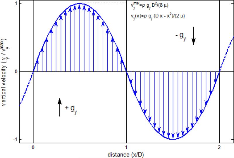
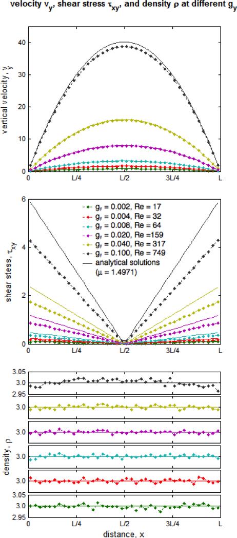
We employ the methodology of Backer et al.3 to determine empirically the dynamic viscosity μ of the DPD fluid by fitting the parabolic velocity profiles developed in periodic Poiseuille flow to the analytical solution of the Navier-Stokes equations. A system of size 40×20×20 (all lengths are dimensionless with respect to rc) is divided into two regions onto each concurrent body forces (ranging from g = 0.001 up to g = 0.2, dimensionless with respect to kBT/rc) are imposed. Ordinary periodic boundary conditions support the formation of parabolic flow fields (Fig. 1) and no adverse features incur as no solid boundaries need to be introduced. Fully developed flow velocity profiles are obtained after 400,000 time steps of Δt = 0.005 (time is dimensionless with respect to ) by locally averaging quantities for 5,000 time steps in cubic bins of size 2. The stress tensor is computed with a stress volume formulation at the particle level with the Irving-Kirkwood model (cf. Fan et al.15) and pressure is one third of its trace. As an alternative comparison of the measured viscosity, we employ a theoretical estimate of viscosity obtained by Marsh et al.37 with a analytical description of the DPD system with Fokker-Planck equations.
FIGURE 1.
Exact solution of periodic Poiseuille flow. By applying two opposing body forces on all fluid particles and periodic boundary conditions in all three directions, one obtains counter-Poiseuille flow without the need to incorporate no slip boundary conditions and their DPD associated issues. The properties of the fluid, in particular its viscosity, can then be determined from the Poiseuille flow.
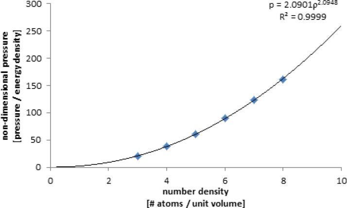
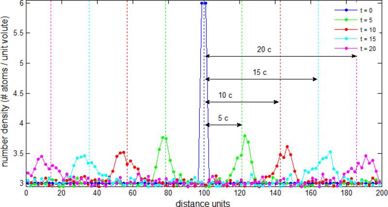
Because of the potential for a breakdown of the incompressible fluid flow approximation with DPD systems (otherwise inherent in continuum based methods for simulating viscous blood flow), we determine a “speed of sound” in the DPD fluid.18 This is conducted empirically by analyzing the propagation velocity of pressure pulses with a system of size 200×10×10 (as described above) and applying periodic boundary conditions. The number density is n = 3.0, except in the region 98.0 ≤ x ≤ 102.0 where n = 6.0 is applied. The spatial domain is divided into layers of size 2 (in the x direction) and particle velocity is averaged at teach time step. For comparison, speed of sound is alternatively computed with c2 = ∂p/∂ρ at constant temperature14 – an equation of state, pressure as a function of density p(ρ), is determined in a cube of size 10 with periodic boundary conditions applied until equilibrium is achieved (with n ranging from n = 3.0 up to n = 8.0).
No-slip boundary conditions in complex geometries
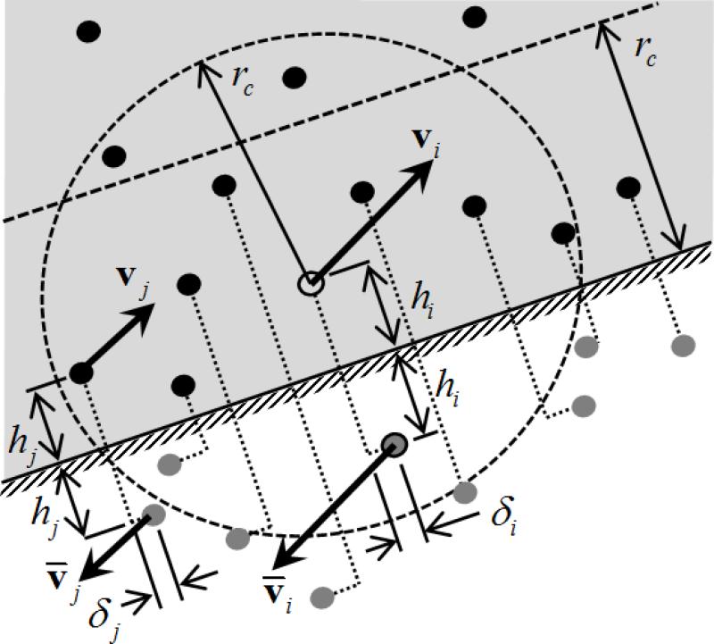
We consider complex walls with a connected mesh of triangular elements, each representing a planar solid wall onto which no-slip conditions are applied. Only particles with the triangular wall inside their radius of influence are subjected to this solid boundary condition. Inward normals and isoparametric transformations are defined with consistent counter-clockwise node numbering. Penetration of particles into the wall is prevented by specular reflection. Double and triple reflections on adjacent triangles might occur because the connected mesh enclosing the DPD fluid is concave, and are considered. To enforce no-slip and the development of boundary layers, we adapt the methodology of Willemsen et al.50 for each triangular element in a local sense. The methodology is described in full in the Appendix. Fictitious particles are generated by reflecting fluid particles across the triangular plane (filling the empty space beyond it) and viscous and random interaction forces between the current particle and the fictitious particles are included in the DPD pair-wise computations. The velocities of the fictitious particles are inverted such that equilibrated shear layers are developed across the wall and velocity is zero on the wall (Fig. 2). Velocities of individual particles near the wall are not generally parallel to the wall, but the resultant average transversal component of the velocity field is approximately zero. If the wall is moving (as in Couette flow), twice the wall velocity is summed.50 A small random parallel shift is added since in DPD no viscous interaction occurs between particles with orthogonal velocity difference and relative position.50 In order to eliminate the pressure imbalance experienced by particles within the region of influence of the wall (as space beyond it is empty), a normal force that mimics the effect of fluid fictitiously occupying the empty space is added: assuming a uniform density in this region, the normal repulsive force is given f = aπn(1–h)3(1+3h)/12, where h is the normal distance of the particle to the wall.50
FIGURE 2.
Schematic of the implementation of the no-slip boundary condition. Particles moving across the wall are reflected with specular reflection. Particles within the zone of influence of the wall have viscous and random interactions with fictitious particles such that an equilibrated shear layer is developed and zero tangential velocity lies at the wall surface. An extra repulsive force is considered accordingly to balance the empty space across the wall and mimic existence of fluid.
Complex geometries
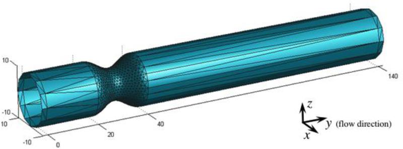
Meshes of complex wall geometries are constructed using Gambit (Fluent Inc, New York). Curved shapes need a sufficiently fine mesh; on the other hand, planar walls necessitate only one triangle. Rectangular channels need only 2 triangles per wall (top and bottom) and a three dimensional mild stenosis (64% stenosis with R = 10 and entry/exit length of 12R for fully development) is defined with 2,106 triangular elements (Fig. 3). Periodic boundary conditions along the flow direction (on planes y = 0 and y = 140) are imposed. Body forces mimic pressure gradients driving the flow (g = 0.005 for Poiseuille flow simulation and g = 0.015 for the stenosis respectively). Top and bottom wall velocities of ±2 were considered for Couette flow boundary conditions.
FIGURE 3.
Geometry of a three-dimensional stenotic channel. A 64% stenosis with entry length/exit length 12R for fully developed flow is modeled using 2,104 triangular surfaces. No-slip boundary conditions are imposed on each of the triangles constituting the wall.
Fluid particle seeding for the initial condition of the rectangular channels of size 40×10×10 (periodic on y and z directions, width D = 40) employs a lattice of size rc with 3 particles per element (one particle in the middle of each lattice leftward face) and results in 12,000 particles. Whenever the domain assumes complex shapes, a mesh generator is employed and we seed particles on the vertexes of a uniform tetrahedral mesh of the stenotic channel such that n ≈ 3.
Platelet Model
Each platelet is modeled with 444 particles on a triangular mesh of an ellipsoid of size 4×4×2 (an oblate spheroid). This configuration is adapted from existing red blood cell particle models to the platelets’ usual discoid shape.39,42 Harmonic bonds in between platelet particles and dihedral angles between adjacent triangles are defined (with potentials VB = Kb(r– r0)2 and VD = Kd (1 + cos ϕ) respectively, where r is bond length and ϕ the angle between two adjacent triangles). We consider equilibrium length as the average of bond length in the initial configuration, r0 = 0.3, and bond and dihedral energies of Kb = 104 and Kd = 102 (non-dimensional with respect to and kbT respectively). Harmonic bonds confer a solid like behavior and an elastic ability to recover from deformation, whereas dihedral angles grant the membrane with in-plane bending stiffness. The tightly bound platelet membrane particles prevent fluid particles from penetrating the platelets and result in a positive response to the pressure force the fluid exerts on their exterior. We have conducted parametric studies to determine the coarse-grained platelet model, particularly to set up its number of particles, their initial spatial locations and bond mapping, and the specific forms of bond and dihedral potential energies and their constants. Once the geometric aspects of the platelet model were fixed (with a triangular mesh of 444 particles, 2652 bonds and dihedrals per platelet) and the specific forms of bond and dihedral potential energies were chosen (harmonic potentials), constants Kb and Kd were obtained with parametric and sensitivity analyses such that the behavior of the platelet model possesses the hallmarks of suspension flows and is consistent with pre-existing limited experimental results of micropipette aspiration26 and atomic force microscopy.33 We incorporate 117 platelets with random orientation inside the stenotic channel at the vertexes of another tetrahedral mesh of the fluid domain, resulting in a total system of 153,162 particles.
RESULTS
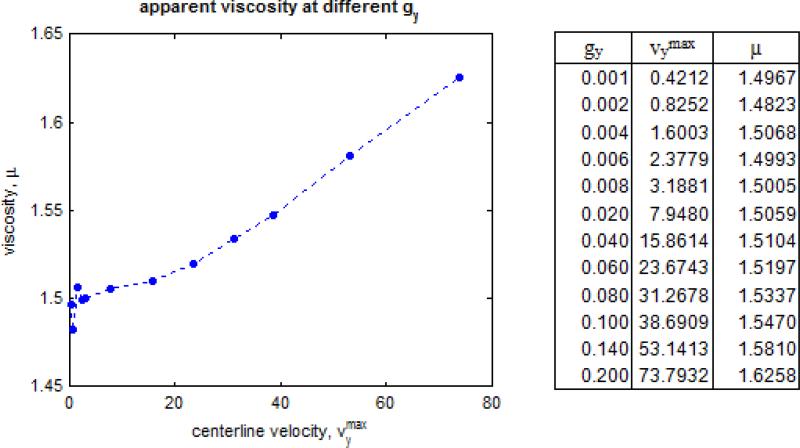
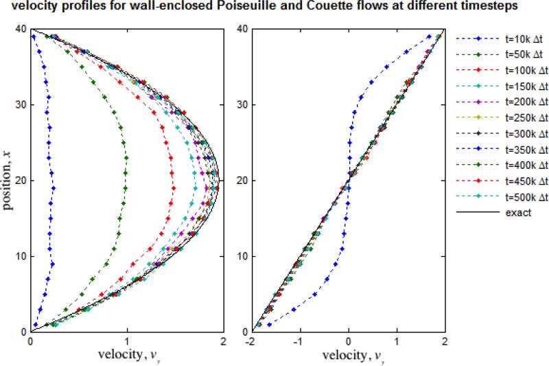
DPD simulations demonstrate the hallmarks of viscous fluid behavior and adequate hydrodynamic characteristics: the system expands to fill void spaces, transmits shear stresses across shear layers, and maintains a clearly defined p vs. ρ equation of state. Free expansion at constant temperature of the DPD fluid allows the determination of an equation of state (Fig. 4), which shows a strong correlation with a quadratic form as previously reported by Groot and Warren,24 increases with increasing density as expected, and at n = 3.0 yields c = 3.8180. Alternatively, pressure wave propagation speed was determined empirically as c = 4.2978 (Fig. 5). Marsh et al.37 estimate for the viscosity of the DPD fluid results in μ = 1.7531. Backer et al.3 have shown that, although the estimate is useful for parameter determination and is able to describe general trends, it deviates considerably from the actual viscosity inferred with the periodic Poiseuille flow method by fitting velocity profiles to the Poiseuille analytical solution, which results in the consistent value of μ = 1.4971 when g < 0.04 and maximum velocity remains small or similar when compared with the measured “speed of sound” (Figs. 6 and 7). We observed a breakdown of the Poiseuille approximation for higher g and values corresponding to increasing Reynolds numbers (computed with the averaged maximum velocity at the centerline of the parabolic velocity profile, μ and n of the DPD fluid, and the width of the channel D): the parabolic shape is lost, shear stress is badly estimated, and mild to severe density gradients appear in the DPD solution (Fig. 6). The apparent viscosity determined by fitting to the Poiseuille solution (Fig. 7) increases, and DPD underestimates the velocity and shear stress profiles if the consistent value of viscosity obtained for lower regimes is considered for the exact solution (not shown). The no-slip boundary condition does not introduce any difficulty and boundary layers are appropriately developed – the steady state Poiseuille and Couette flow benchmarks are properly approximated for regimes with (Fig. 8).
FIGURE 4.
Equation of state of the DPD fluid. Variation of pressure vs. density upon expansion at constant temperature. Speed of sound in the DPD fluid is obtained indirectly as the square root of the slope of the curve describing the equation of state 14, and at n = 3.0 results in c = 3.8180.
FIGURE 5.
Propagation of a pressure pulse. A compression-type wave propagates through the fluid at constant speed. Dissipation naturally occurs and the pressure pulse loses intensity and spreads across space as it travels. Speed of sound is inferred directly and empirically from the simulation resulting in c = 4.2978.
FIGURE 6.
Velocity, shear stress and density profiles developed with periodic Poiseuille for different body forces/pressure gradients/Reynolds numbers (dots – numerical simulations, lines – exact solutions). We observe a breakdown of the approximation of incompressible fluid flow as the maximum velocity increases and becomes comprarable or higher than c. Although parabolic profiles are obtainable up to high velocities and Re 750, shear stress accros the fluid is poorly approximated at this velocity range and mild density gradients develop as .
FIGURE 7.
Apparent viscosity calculated with periodic Poiseuille flow. Viscosity was determined by fitting the observed velocity profile to the exact Poiseuille solution. We observe a constistent increase in apparent viscosity as body force and maximum velocity increases, and the aproximation of incompressible fluid breaks down.
FIGURE 8.
Poiseuille and Couette flow in channels enclosed by solid walls. We have validaded our methodology for imposing no-slip boundary conditions with the Poiseuille and Couette flow benchmarks. The velocity profiles are well approximated. Shear stress profiles shows excelent agreement with the analytical solutions for incompressible fluids (linear and constant respectively) and density fluctuations near the wall do not occur remaing constant across the channel (not shown).
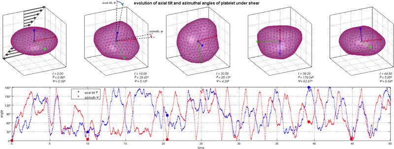
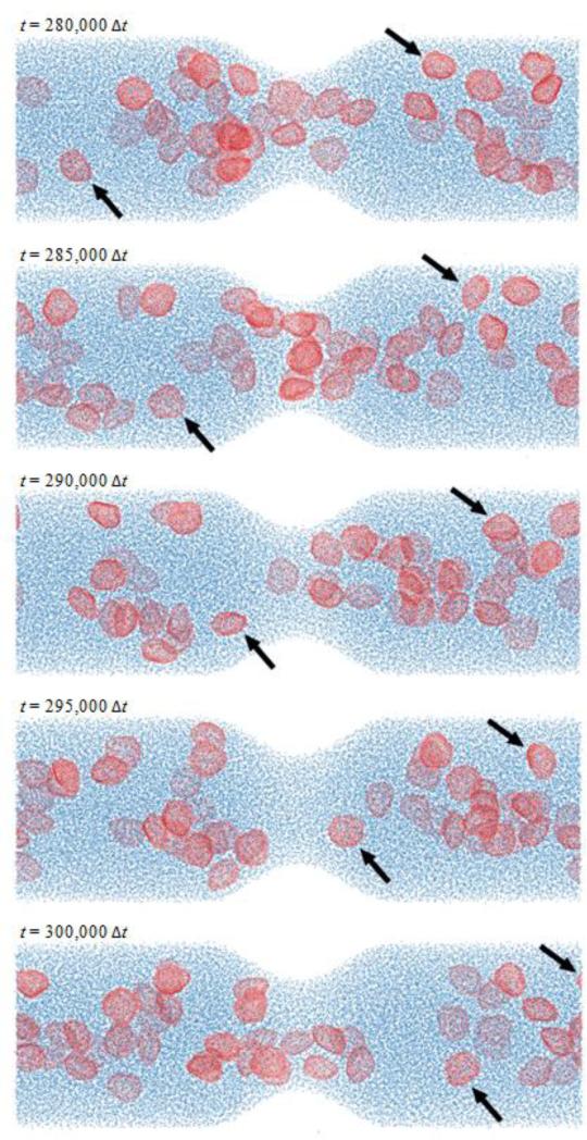
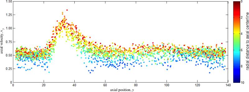
The coarse-grained model for platelets shows appropriate phenomenological response. The deformable membrane keeps its discoid shape after equilibration with the surrounding fluid particles while preventing them from crossing in. When suspended under shear flows, we observe a multitude of platelet motions that can be identified as the three-dimensional counterparts of the well-known Jeffery's orbits of a two-dimensional ellipsoid under shear (Fig. 9 and Movie S1): the platelet turns and spins along its axes on the direction of shear.28 Portion of this movement is certainly dictated by the random component of the DPD forces and the complex nature of the system (e.g. the instantaneous 3D orientation of the platelet), but periods of ordered and consistent flipping on its axes are clearly observed (Fig. 9). Simulations of suspensions of multiple platelets flowing across a stenosis show remarkable behavior. Platelets are transported with the flow (with Reynolds number of Re ≈ 20 computed with averaged maximum velocity at the centerline of the inlet cross-section, μ and n of the DPD fluid, and inlet diameter D), flipping and colliding with the wall and with other platelets. Platelets accelerate through the stenosis core flow, while near wall platelets and those trapped in the recirculation zones show lower characteristic velocities and longer residence times (Figs. 10 and 11, Movie S2). Platelet axial velocity is steady with approximate value of 0.50 on the wider portion of the channel and accelerates through the neck of the stenosis up to 1.20 (Fig. 11). We do not observe any accumulation or rarefaction of fluid in any region and density remains approximately constant everywhere. When only fluid is considered (no platelets suspended), the DPD flow fully satisfies the continuity equation, i.e. describing constant flow rates at each cross section of the channel at all cross-sections (not shown). When individual platelet velocities are considered for computing an average representative velocity across corresponding cross-sections (based on platelet centroid velocity), one obtains 50 ≈ 43.2, an acceptable estimation/validation of the behavior of the heterogeneous flow of platelet suspensions (considering that continuity is only valid for homogeneous incompressible fluids, and only marginally applicable for an highly heterogeneous platelet suspension such as modeled by the DPD approach).
FIGURE 9.
Coarse-grained finite-size platelet modeled suspended in shear flow. We employ 444 particles, defined with a triangular mesh, to describe an ellipsoid platelet membrane connected by harmonic bonds and harmonic dihedral angles. The model shows great phenomenological behavior and we observe the platelet undergoing three-dimensional counterparts of Jeffery's motions, flipping and spinning on its axes. Movie S1 of supplemental material depicts a portion of the simulated platelet self-orbiting motion for 15,000 time steps.
FIGURE 10.
Suspension of platelets flowing in a three-dimensional stenotic channel. The Reynolds number of this flow is approximately 20 (computed with average maximum velocity at the centerline of the inlet cross-section, μ and n of the DPD fluid and diameter D). Extraordinary phenomenological behavior is observed - platelets are transported with the flow, flipping and colliding with other platelets and the wall, accelerating across the stenosis neck and becoming trapped in the recirculation zones distally. Movie S2 of supplemental material depicts the transport of platelets in the stenotic channel during 5,000 time steps at 3 different stages of the simulation (for t = [0; 5,000Δt], t = [95,000Δt; 100,000Δt], and t = [195,000Δt; 200,000Δt].
FIGURE 11.
Axial velocity of platelet centroid vs. axial distance and radial distance. Platelet velocity is higher across the stenosis neck and in core flow, whereas near-wall platelets and those trapped in the recirculation zones (Fig. 10) have lower velocities and longer residence times. Direct comparison of platelet centroid velocity with the continuity equation for incompressible homogenous fluids results in a decent estimation/validation of the behavior of platelets across the stenosis.
DISCUSSION
Our particle based model considers platelets as deformable finite bodies, a significant advantage over previous studies with platelets as point particles with no surface of volume,41 and results in a built-in two-way coupling between platelets and fluid. Coarse-grained finite-sized platelet models allow for a natural specification of diverse platelet-platelet, platelet-wall interactions,38 and with other relevant constituents of blood, particularly fibrinogen polymerizing into the fibrin network.8 As opposed to the model of Yun et al.,52 which considers platelets as finite-sized rigid ellipsoids, ours deform in response to the surrounding environment.
Flow-induced platelet activation occurs in response to stress on platelet constituents, which can be represented to a certain extent by the continuum approach up to the μm-level; however, the molecular mechanisms of platelet activation and shape change are on the order of nm. Coupling of such disparate length and timescales between molecular and macroscopic transport phenomena represents a major computational and modeling challenge when using traditional continuum-based approaches. A multi-scale approach based on particle models for bridging the gap between macroscopic flow scales and the cellular scales is a more efficient approach. In conjunction with the top-scale model present here (Fig. 10) where multiple platelets suspended in viscous fluid interact with the fluid, the enclosing walls and with each other, we are currently developing a cellular-scale model employing molecular dynamics with nm length scales (bottom-up model). A single platelet is modeled with multiple sub-constituents (cytoskeleton, a finite thickness lipid bilayer as membrane, and cytoplasm) evolving during activation as pseudopodia grow and the platelets lose their natural discoid shape. Coupling of the two models represents a true multi-scale fundamental model of flow-induced thrombogenicity – information is passed between both scales: individual platelet activation at the top-scale is obtained from evolution of the cellular scale occurring in response to environment conditions at the top-scale and communicated down to the cellular-scale.
Solid boundaries enclosing DPD systems with appropriate no-slip boundary conditions poses a major challenge for DPD simulations and diverse methodologies have been developed over the years, each with their own advantages and problems. Solid walls modeled as layers of frozen particles15,19 introduce severe density fluctuations near the wall and may allow the penetration of fluid particles.41 Other methodologies employ adaptive forces,34,40 but their generalization to complex geometries is quite cumbersome. We develop a general no-slip boundary condition for broad application to complex shaped walls by adapting the methodology proposed by Willemsen et al.50 and the concept of equilibrated shear layers (Fig. 2). Solid wall boundaries should address the following conditions: (i) prevent penetration of fluid particles; (ii) enforce no-slip condition and develop a boundary layer; and (iii) prevent imbalances that lead to spurious inhomogeneous fluctuations of density and pressure. Our methodology satisfies these conditions, shows accurate behavior as compared with the Poiseuille and Couette flow benchmarks (Fig. 8), and is easily applied to complex geometries by using triangular meshes (Fig. 3).
As our goal is to employ the DPD formulation to approximate incompressible fluid flow, in particular the resulting density, velocity and stress fields resolved with spatial and temporal averaging of the particle simulations. We conducted simulations of benchmark solutions (Poiseuille and Couette flow) under different velocity regimes and we observed that the approximation of incompressible fluid flow breaks down whenever velocities are comparable to or higher than the speed of sound of the DPD system (Fig. 6). Fedosov et al.18 have observed a deviation from the Navier-Stokes solution on lid-driven cavity flow and reported the existence of a velocity limit, particularly associated with compressibility effects. Our analysis was conducted with periodic Poiseuille flow such that its culprit cannot be attributed to adverse features due to the introduction of no-slip boundary conditions. Although parabolic profiles in Poiseuille flow can be achieved over a range of flow rates (up to Re 750), we observe a significant increase of apparent viscosity when (as determined by fitting the velocity profile to the analytical solution, Fig. 7). A considerable breakdown of the approximation of the linear shear stress profile is noted, as well as mild to severe gradients in density (Fig. 6). A finite limit on shear stress in DPD systems seems to exist, beyond which parabolic profiles may not be obtained. Under such conditions we have observed in our stenosis model sharp profiles usually associated with shear-thickening fluids, and the development of a clearly defined shock wave for extreme pressure differentials. These effects might be attributed to the compressibility of the DPD system and result in a breakdown of the approximation of the hydrodynamics of incompressible fluids. In order to approximate accurately incompressible fluids subjected to higher Reynolds number flows, a larger system with a higher characteristic length and covering greater computational distances (such that the ratio rc/D is smaller) will be required, resulting in a significant increase in the number of particles and computational costs.
Our current modeling effort is hampered by several limitations. Our coarse-grained platelet model does not capture in full extent the behavior of platelets in suspension. We model platelet membranes as ensembles of bound particles composing a membrane with sufficiently extensional and bending stiffness (platelets behave almost rigidly prior to activation), but the lack of experimental data on the mechanical response of an individual platelet curtails the development of more accurate and rigorous modeling. Notwithstanding, our coarse-grained model compares favorably with existing data sets of platelet mechanical deformation, and demonstrates appropriate rheological behavior – self-orbiting motions in shear flow and other hydrodynamic and physiologic characteristics in a stenosis model. Platelets are known to interact biochemically with each other and with walls and we have not included such effects at the current stage. The major limitation of our current study for the in vivo description of thrombosis is the absence of red blood cells and other key players in the complex rheological behavior of blood and their role in flow-mediated thrombosis and platelet activation, aggregation, and adhesion. Platelets and red blood cells interact, and in order to have a rigorous description of blood flow, it is necessary to account for their presence and such interactions. Consequently, our simulations should not be observed as depicting the physiologic settings of blood flow in the vasculature – in fact, we are modeling a complex heterogeneous fluid composed of an incompressible fluid phase and suspended particulate which can be viewed as a suspension of platelets flowing in a stenotic channel with inert walls.
SUMMARY AND CONCLUSIONS
The hydrodynamic characteristics of viscous fluid flow obtained with the DPD methodology were studied and compared favorably with continuum based viscous flow solutions. To enable DPD simulation in complex 3D geometries such as found in the vasculature, we have developed a no-slip boundary condition tailored to render in a feasible manner complex three-dimensional geometries enclosing the DPD fluid. A breakdown of the validity of the incompressibility approximation was observed with increasing velocities, possibly due to the inability of DPD particles ensembles to support and transmit properly large shear stresses, indicating that larger simulations must be considered to extend beyond the low Reynolds number microfluidic flows to the arterial scales with their characteristics medium-to-high Reynolds number flows.
We further present a top-scale model of platelet suspension flowing in three-dimensional stenotic channels. The platelets are modeled as coarse-grained finite-sized ensembles of particles. We were able to observe well-established blood particulates unique dynamics such as self-orbiting motions of platelets under shear associated with Jeffery's orbits, as well as favorable platelet-wall and platelet-platelet interactions in flow inside the stenosis.
Our current and future studies include validation of our multiscale modeling effort to account for platelet morphological and functional changes upon activation. This is achieved by interfacing the current DPD mesoscale model with a cellular nano-to-microscale model of flow-induced platelet activation (including the platelet cytoskeleton and bilayer membrane, based on a coarse grained molecular dynamics model) in a fully coupled multiscale approached. The multiscale model will be further developed to include other key players of blood rheology (particularly red blood cells and fibrin polymerization), and is intended to capture platelet activation, aggregation and adhesion and others aspects of flow-mediated thrombosis in an attempt to render physiologic applicability to our multiscale model.
Supplementary Material
ACKNOWLEDGEMENTS
This study was funded by grants from the National Institute of Health: NHLB R21 HL096930-01A2 (DB), NIBIB Quantum Award Phase I R01 EB008004-01 (DB), and Quantum Award Implementation Phase II-U01 EB012487-0 (DB). We thank and acknowledge the constructive suggestions made by three anonymous reviewers.
APPENDIX
Dissipative particle dynamics formulation
Dissipative particle dynamics is a mesoscopic particle method,24,27 where each particle represents a molecular cluster rather than an individual atom, and can be thought of as a soft lump of fluid. The DPD system consists of N point particles of mass mi, position ri and velocity vi. DPD particles interact through three forces: conservative , dissipative and random forces given by
| (1) |
| (2) |
| (3) |
where eij = rij/rij, with rij = ri – rj and rij = (rij · rij)1/2, is a unit vector in the direction of particles i and j, and vij = vi – vj is the relative velocity of particle i with respect to particle j. The coefficients γ and σ define the strength of dissipative and random forces, respectively. In addition, ωD and ωR are weigtht functions, and ξij is a normally distributed random variable with zero mean, unit variance and ξij = ξji. All forces are truncated beyond the cutoff radius rc, which defines the length scale in the DPD system. The conservative force is given by
| (4) |
where aij is the conservative force coefficient between particles i and j. The random and dissipative forces form a thermostat and must satisfy the fluctuation-dissipation theorem in order for the DPD system to maintain equilibrium temperature T.14 This leads to
| (5) |
| (6) |
where kB is the Boltzmann constant. The choice for the weight functions is
| (7) |
where k = 1 for the original DPD method. However, other choices (e.g. k = 0.25) have been used in order to increase the viscosity of the DPD fluid.15,18 To mimic the effect of a pressure gradient driving the flow of particles, a body force, given by
| (8) |
acts in particles located within certain regions of space. Particle i can have bonds with other particles. If particle i is bound to particle k, there exists a force in particle i acting in the eik direction with magnitude determined by the gradient of the harmonic bond potential
| (9) |
where is the force constant and r0 is the distance when the force is null. Torsional energy is added with the definition of proper dihedrals: Particle i can be part of dihedrals. If particles i,j k, and l form a proper dihedral, two planes with normal vectors m and n can be defined with particles i, j and k, and j, k, and l, respectively, i.e.
| (10) |
| (11) |
The torsional angle is defined as
| (12) |
with the sine and cosine of the torsional angle being given by
| (13) |
| (14) |
The harmonic dihedral potential is defined as
| (15) |
where is the torsion constant, ϕ0 is the angle of minimum potential, and nijkl is the multiplicity of minima in a full rotation. Finally, the forces exerted in particle i due to the harmonic bond and dihedral potentials are obtained with the computation of the gradient of the potentials, on which the chain rule is useful, i.e.
| (16) |
| (17) |
The time evolution of velocities and positions of particles is determined by Newton's second law of motion
| (18) |
| (19) |
which are integrated using the modified velocity-Verlet algorithm.24 Fluid particles will have no bonds or dihedrals associated to them, i.e. if particle i is a fluid particle In our simulations, we consider: (i) all particles have the same mass (i.e. mi = m for all i), (ii) share equal conservative force coefficients (i.e. aij = a for all i and j), (iii) a negative pressure gradient is directed along the ey direction (i.e. gy = g and gx = gz = 0), (iv) all bonds and dihedrals are equal (i.e. share the same functional form of potential, with , , nijkl = 1 and ϕ0 = 0).
No-slip boundary condition implementation
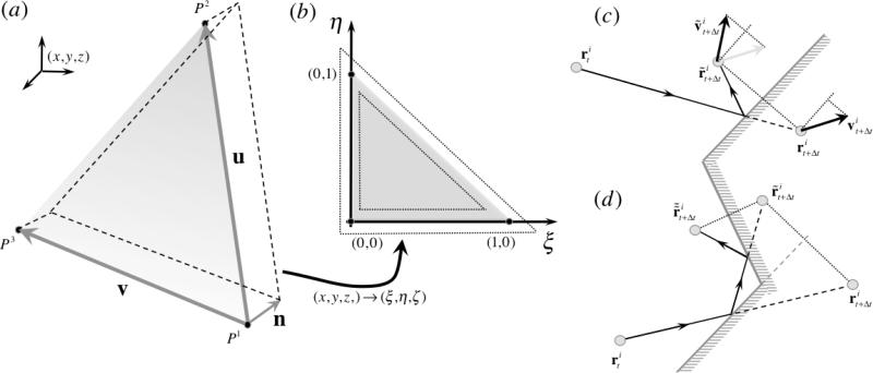
We have generalized and implemented Willemsen et al.50 no-slip boundary condition into a three dimensional framework. The boundary condition is composed of three distinct components: (i) inclusion of an additional conservative force to balance void space beyond the wall, (ii) inclusion of additional dissipative and random forces due to interaction with fictitious particles, and (iii) specular reflection of particles crossing a solid wall. Let us consider a particle i located at and let us consider a triangular wall P composed of vertices (P1,P2,P3), each with coordinates for j = 1, 2, 3 (Fig. 12 (a)). With the objective of treating triangles with any orientation, we define a isoparametric transformation from the (x, y, z) coordinate system into a general coordinate system (ξ,η,ζ) and triangle P becomes triangle P̄ composed of vertices (P̄1,P̄2,P̄3) with coordinates for j = 1, 2, 3 given by (0,0,0), (1,0,0), and (0,1,0), respectively, in the general coordinate system (ξ,η,ζ) (Fig. 12 (b)). In order to compute the transformation from P to P̄, it is useful to define vectors u = P2 – P1, v = P3 – P1, n = (u×v)/|u×v|, ū = u/|u| and v̄ = (v – (ū·v)ū)/|v – (ū·v)ū| such that (ū,v̄,n) form an orthonormal basis. Vectors u and v correspond to two edges of triangle P, ū is an unit vector aligned with one triangular edge and n is a unit normal defining the interior side of the triangular wall (defined by counter-clockwise numbering of triangular vertices). The Jacobian J of the transformation is given by
| (20) |
and the transformation matrix M is given by
| (21) |
The first step of the boundary condition infers if particle i is within the region of influence of the triangular wall, defined as a layer of thickness rc above the triangular wall (Fig. 12 (b)) – if outside, the particle does not suffer the influence of the wall, but if inside, it does, and hence, additional interactions in the force computation must be included. Three additional interaction forces will be added to particle i: dissipative and random interactions with fictitious particles beyond the wall and a conservative force that balances particle i with the void space existing beyond the wall.
FIGURE 12.
The generalization of Willemsen et al.50 no-slip boundary condition employs isoparametric transformations from all triangular elements defining the complex wall geometry defined in the coordinate system (x,y,z) into coordinate system (ξ,η,ζ) ((a) and (b)). Specular reflection is enforced to particles that cross the wall by reflecting their normal position and normal velocity component (c). Walls enclosing the DPD fluid are concave; hence an algorithm to handle multiple reflections was developed (d).
The position of the particle i with respect to vertex P1 is given by vector mi = ri – P1, which transforms to the general coordinate system simply by m̄i = Mmi and results in coordinates . The necessary conditions for particle i to be inside the region of influence of triangular wall P are , , , and (Fig. 12 (b)).
The additional conservative force introduced to particle i due to the boundary condition is quite straightforward – note that is the normal distance of particle i to the wall and n is a unit vector normal to the wall (and directed inwards), thus with (cf. Methods - No-slip boundary conditions in complex geometries).
Particle i has M neighbors, i.e. particles k located at rk with k = 1,2,..,M whose distance to particle i is lower than cut-off radius rc. These neighbor particles k will originate fictitious particles k̃ with which particle i interacts if the fictitious particle lays within one cut-off radius of particle i. Thus, the normal distance of particle i to the wall will dictate the thickness of the layer of neighbors that must be reflected beyond the wall, i.e. (Fig. 2). The transformation is applied to all neighbor particles k, i.e. mk = rk – P1 and m̄k = Mmk such that is the normal distance to the wall of neighbor particle k. If , then a reflected fictitious particle k̃ will be considered and dissipative and random interactions between fictitious particle k̃ and particle i included. The location of fictitious particle r̃k is given by where hr is the random shift parallel to triangular wall P (Fig. 2). The random shift hr is generated with the aid of two random numbers, the random shift distance hr and the random shift orientation θr both being generated with independent Gaussian random number generators with zero mean and variance rc and π respectively, and is given by
| (22) |
Random interaction forces are determined simply by distance between fictitious particle k̃ and particle i, i.e. rik̃ = ri – r̃k, whereas dissipative interaction forces take into account the relative velocity between both, i.e. vik̃ = vi – ṽk. The velocity ṽk of the fictitious particle k̃ is the reflected velocity of neighbor particle k with the tangential component reversed, and is given by ṽk = –vk – 2(vk · n)n (Fig. 2). A similar methodology is employed to account for the interaction between particle i and its corresponding fictitious particle ĩ if . To conclude, the additional conservative, random and dissipative interaction forces added to particle i by the imposition of the no slip boundary condition on triangular wall P are
| (23) |
where M̃ is the number of fictitious neighbors of particle i introduced.
Lastly, specular reflection of particles that cross the triangular wall P is enforced. We employ the same transformation to evaluate the location of a given particle i with respect to the wall and we define a layer of thickness rc above the wall (as for the force calculations) but with a clearance of size rc beyond the triangle edges (Fig. 12 (b)) to account for the possibility of particles that are slightly offset with triangle P but traveling towards it. Particle i is inside the region of possible reflection on triangular wall P if satisfies all of these conditions: , , , and (Fig. 12 (b)). The location of particle i in the current time step and previous time step define the line of its trajectory, i.e. with λ ∈]– ∞, ∞[. We identify the location in the trajectory of the intersection point between the line and the triangular wall plane by evaluating λ with
| (24) |
which will translate into a valid intersection if 0 < λ < 1. Once λ is determined, the location of the intersection point is given by . The intersection point is not guaranteed to be in the triangular region, thus we employ the transformation once again to obtain mp = pi – P1, m̄p = Mmp and evaluate if the intersection point is indeed in the triangular wall, i.e. if and only if , , and (note that in this case ).
If so, the particle should be reflected, i.e. its reflected current position is updated by adding to twice the normal component of the trajectory beyond the wall (Fig. 12 (c)), i.e.
| (25) |
and the velocity is also updated by subtracting twice the normal component (Fig. 12 (c)), i.e.
| (26) |
Finally, because we consider walls composed of multiple adjacent triangles defining a concave surface, it is necessary to account for possible multiple reflections occurring in the same time step (Fig. 12 (d)), i.e. a particle is reflected from one triangle in such a way that it should be reflected by adjacent triangles. We implement such multiple reflections for the cases on which the intersection point of the first reflection was located within one cut-off radius inside the triangle (Fig. 12 (b)) determined by conditions , or , or , each condition corresponding to one edge of the triangular wall. In such case, the previous position is updated with the intersection point, i.e. , and the same algorithm is performed with respect to the corresponding adjacent triangles.
Footnotes
REFERENCES
- 1.Aidun CK, Lu YN. Lattice Boltzmann Simulation of Solid Particles Suspended in Fluid. J Stat Phys. 1995;81:49–61. [Google Scholar]
- 2.Anand M, Rajagopal K, Rajagopal KR. A model for the formation and lysis of blood clots. Pathophysiol Haemo T. 2005;34:109–120. doi: 10.1159/000089931. [DOI] [PubMed] [Google Scholar]
- 3.Ataullakhanov FI, Panteleev MA. Mathematical modeling and computer simulation in blood coagulation. Pathophysiol Haemo T. 2005;34:60–70. doi: 10.1159/000089927. [DOI] [PubMed] [Google Scholar]
- 4.Backer JA, Lowe CP, Hoefsloot HCJ, Iedema PD. Poiseuille flow to measure the viscosity of particle model fluids. J Chem Phys. 2005;122 doi: 10.1063/1.1883163. [DOI] [PubMed] [Google Scholar]
- 5.Bevers EM, Comfurius P, Zwaal RF. Mechanisms involved in platelet procoagulant response. Advances in experimental medicine and biology. 1993;344:195–207. doi: 10.1007/978-1-4615-2994-1_15. [DOI] [PubMed] [Google Scholar]
- 6.Bluestein D. Research approaches for studying flow-induced thromboembolic complications in blood recirculating devices. Expert review of medical devices. 2004;1:65–80. doi: 10.1586/17434440.1.1.65. [DOI] [PubMed] [Google Scholar]
- 7.Boryczko K, Dzwinel W, Yuen DA. Dynamical clustering of red blood cells in capillary vessels. J Mol Model. 2003;9:16–33. doi: 10.1007/s00894-002-0105-x. [DOI] [PubMed] [Google Scholar]
- 8.Boryczko K, Dzwinel W, Yuen DA. Modeling fibrin aggregation in blood flow with discrete-particles. Computer methods and programs in biomedicine. 2004;75:181–194. doi: 10.1016/j.cmpb.2004.02.001. [DOI] [PubMed] [Google Scholar]
- 9.Buxton GA, Verberg R, Jasnow D, Balazs AC. Newtonian fluid meets an elastic solid: Coupling lattice Boltzmann and lattice-spring models. Phys Rev E. 2005;71 doi: 10.1103/PhysRevE.71.056707. [DOI] [PubMed] [Google Scholar]
- 10.Chan PCH, Leal LG. Motion of a Deformable Drop in a 2nd-Order Fluid. J Fluid Mech. 1979;92:131–170. [Google Scholar]
- 11.Crowl L, Fogelson AL. Analysis of mechanisms for platelet near-wall excess under arterial blood flow conditions. J Fluid Mech. 2011;676:348–375. [Google Scholar]
- 12.Crowl LM, Fogelson AL. Computational model of whole blood exhibiting lateral platelet motion induced by red blood cells. Int J Numer Meth Bio. 2010;26:471–487. doi: 10.1002/cnm.1274. [DOI] [PMC free article] [PubMed] [Google Scholar]
- 13.Dupin MM, Halliday I, Care CM, Alboul L, Munn LL. Modeling the flow of dense suspensions of deformable particles in three dimensions. Phys Rev E. 2007;75 doi: 10.1103/PhysRevE.75.066707. [DOI] [PMC free article] [PubMed] [Google Scholar]
- 14.Espanol P. Hydrodynamics from Dissipative Particle Dynamics. Phys Rev E. 1995;52:1734–1742. doi: 10.1103/physreve.52.1734. [DOI] [PubMed] [Google Scholar]
- 15.Fan XJ, Phan-Thien N, Chen S, Wu XH, Ng TY. Simulating flow of DNA suspension using dissipative particle dynamics. Phys Fluids. 2006;18 [Google Scholar]
- 16.Fedosov DA, Caswell B, Karniadakis GE. A Multiscale Red Blood Cell Model with Accurate Mechanics, Rheology, and Dynamics. Biophysical journal. 2010;98:2215–2225. doi: 10.1016/j.bpj.2010.02.002. [DOI] [PMC free article] [PubMed] [Google Scholar]
- 17.Fedosov DA, Karniadakis GE. Triple-decker: Interfacing atomistic-mesoscopic-continuum flow regimes. J Comput Phys. 2009;228:1157–1171. [Google Scholar]
- 18.Fedosov DA, Pivkin IV, Karniadakis GE. Velocity limit in DPD simulations of wall-bounded flows. J Comput Phys. 2008;227:2540–2559. [Google Scholar]
- 19.Feng R, Xenos M, Girdhar G, Kang W, Davenport JW, Deng YF, Bluestein D. Viscous flow simulation in a stenosis model using discrete particle dynamics: a comparison between DPD and CFD. Biomech Model Mechan. 2012;11:119–129. doi: 10.1007/s10237-011-0297-z. [DOI] [PubMed] [Google Scholar]
- 20.Filipovic N, Kojic M, Tsuda A. Modelling thrombosis using dissipative particle dynamics method. Philos T R Soc A. 2008;366:3265–3279. doi: 10.1098/rsta.2008.0097. [DOI] [PMC free article] [PubMed] [Google Scholar]
- 21.Fogelson AL. Continuum Models of Platelet-Aggregation - Formulation and Mechanical-Properties. Siam J Appl Math. 1992;52:1089–1110. [Google Scholar]
- 22.Fogelson AL, Guy RD. Immersed-boundary-type models of intravascular platelet aggregation. Comput Method Appl M. 2008;197:2087–2104. [Google Scholar]
- 23.Girdhar G, Xenos M, Alemu Y, Chiu WC, Lynch BE, Jesty J, Einav S, Slepian MJ, Bluestein D. Device thrombogenicity emulation: a novel method for optimizing mechanical circulatory support device thromboresistance. PloS one. 2012;7:e32463. doi: 10.1371/journal.pone.0032463. [DOI] [PMC free article] [PubMed] [Google Scholar]
- 24.Groot RD, Warren PB. Dissipative particle dynamics: Bridging the gap between atomistic and mesoscopic simulation. J Chem Phys. 1997;107:4423–4435. [Google Scholar]
- 25.Haber S, Filipovic N, Kojic M, Tsuda A. Dissipative particle dynamics simulation of flow generated by two rotating concentric cylinders: Boundary conditions. Phys Rev E. 2006;74 doi: 10.1103/PhysRevE.74.046701. [DOI] [PubMed] [Google Scholar]
- 26.Haga JH, Beaudoin AJ, White JG, Strony J. Quantification of the passive mechanical properties of the resting platelet. Annals of biomedical engineering. 1998;26:268–277. doi: 10.1114/1.118. [DOI] [PubMed] [Google Scholar]
- 27.Hoogerbrugge PJ, Koelman JMVA. Simulating Microscopic Hydrodynamic Phenomena with Dissipative Particle Dynamics. Europhys Lett. 1992;19:155–160. [Google Scholar]
- 28.Jeffery GB. The motion of ellipsoidal particles immersed in a viscous Proceedings of the Royal Society of London. Series A. 1922;102:161–179. [Google Scholar]
- 29.Jesty J, Nemerson Y. The pathways of blood coagulation. In: Beutler E, Lichtman MA, Coller BS, Kipps TJ, editors. Williams Hematology. McGraw–Hill; New York: 1995. pp. 1227–1238. [Google Scholar]
- 30.Kuharsky AL, Fogelson AL. Surface-mediated control of blood coagulation: the role of binding site densities and platelet deposition. Biophysical journal. 2001;80:1050–1074. doi: 10.1016/S0006-3495(01)76085-7. [DOI] [PMC free article] [PubMed] [Google Scholar]
- 31.Ladd AJC. Numerical Simulations of Particulate Suspensions Via a Discretized Boltzmann-Equation .1. Theoretical Foundation. J Fluid Mech. 1994;271:285–309. [Google Scholar]
- 32.Ladd AJC. Numerical Simulations of Particulate Suspensions Via a Discretized Boltzmann-Equation .2. Numerical Results. J Fluid Mech. 1994;271:311–339. [Google Scholar]
- 33.Lee I, Marchant RE. Force measurements on platelet surfaces with high spatial resolution under physiological conditions. Colloid Surface B. 2000;19:357–365. doi: 10.1016/s0927-7765(00)00144-2. [DOI] [PubMed] [Google Scholar]
- 34.Lei HA, Fedosov DA, Karniadakis GE. Time-dependent and outflow boundary conditions for Dissipative Particle Dynamics. J Comput Phys. 2011;230:3765–3779. doi: 10.1016/j.jcp.2011.02.003. [DOI] [PMC free article] [PubMed] [Google Scholar]
- 35.Li X, Popel AS, Karniadakis GE. Blood-plasma separation in Y-shaped bifurcating microfluidic channels: a dissipative particle dynamics simulation study. Physical biology. 2012;9:026010. doi: 10.1088/1478-3975/9/2/026010. [DOI] [PMC free article] [PubMed] [Google Scholar]
- 36.MacMeccan RM, Clausen JR, Neitzel GP, Aidun CK. Simulating deformable particle suspensions using a coupled lattice-Boltzmann and finite-element method. J Fluid Mech. 2009;618:13–39. [Google Scholar]
- 37.Marsh CA, Backx G, Ernst MH. Static and dynamic properties of dissipative particle dynamics. Phys Rev E. 1997;56:1676–1691. [Google Scholar]
- 38.Mody NA, King MR. Platelet adhesive dynamics. Part I: Characterization of platelet hydrodynamic collisions and wall effects. Biophysical journal. 2008;95:2539–2555. doi: 10.1529/biophysj.107.127670. [DOI] [PMC free article] [PubMed] [Google Scholar]
- 39.Pan WX, Fedosov DA, Caswell B, Karniadakis GE. Predicting dynamics and rheology of blood flow: A comparative study of multiscale and low-dimensional models of red blood cells. Microvascular research. 2011;82:163–170. doi: 10.1016/j.mvr.2011.05.006. [DOI] [PMC free article] [PubMed] [Google Scholar]
- 40.Pivkin IV, Karniadakis GE. A new method to impose no-slip boundary conditions in dissipative particle dynamics. J Comput Phys. 2005;207:114–128. [Google Scholar]
- 41.Pivkin IV, Karniadakis GE. Controlling density fluctuations in wall-bounded dissipative particle dynamics systems. Physical review letters. 2006;96:206001. doi: 10.1103/PhysRevLett.96.206001. [DOI] [PubMed] [Google Scholar]
- 42.Pivkin IV, Karniadakis GE. Accurate coarse-grained modeling of red blood cells. Physical review letters. 2008;101 doi: 10.1103/PhysRevLett.101.118105. [DOI] [PubMed] [Google Scholar]
- 43.Pivkin IV, Richardson PD, Karniadakis G. Blood flow velocity effects and role of activation delay time on growth and form of platelet thrombi. P Natl Acad Sci USA. 2006;103:17164–17169. doi: 10.1073/pnas.0608546103. [DOI] [PMC free article] [PubMed] [Google Scholar]
- 44.Pivkin IV, Richardson PD, Karniadakis GE. Effect of Red Blood Cells on Platelet Aggregation. Ieee Eng Med Biol. 2009;28:32–37. doi: 10.1109/MEMB.2009.931788. [DOI] [PubMed] [Google Scholar]
- 45.Plimpton S. Fast Parallel Algorithms for Short-Range Molecular-Dynamics. J Comput Phys. 1995;117:1–19. [Google Scholar]
- 46.Sorensen EN, Burgreen GW, Wagner WR, Antaki JF. Computational simulation of platelet deposition and activation: I. Model development and properties. Annals of biomedical engineering. 1999;27:436–448. doi: 10.1114/1.200. [DOI] [PubMed] [Google Scholar]
- 47.Sorensen EN, Burgreen GW, Wagner WR, Antaki JF. Computational simulation of platelet deposition and activation: II. Results for Poiseuille flow over collagen. Annals of biomedical engineering. 1999;27:449–458. doi: 10.1114/1.201. [DOI] [PubMed] [Google Scholar]
- 48.Sui Y, Chew YT, Low HT. A lattice Boltzmann study on the large deformation of red blood cells in shear flow. Int J Mod Phys C. 2007;18:993–1011. [Google Scholar]
- 49.Sui Y, Chew YT, Roy P, Low HT. A hybrid immersed-boundary and multi-block lattice Boltzmann method for simulating fluid and moving-boundaries interactions. Int J Numer Meth Fl. 2007;53:1727–1754. [Google Scholar]
- 50.Willemsen SM, Hoefsloot HCJ, Iedema PD. No-slip boundary condition in dissipative particle dynamics. Int J Mod Phys C. 2000;11:881–890. [Google Scholar]
- 51.Wohl PR, Rubinow SI. Transverse Force on a Drop in an Unbounded Parabolic Flow. J Fluid Mech. 1974;62:185–207. [Google Scholar]
- 52.Yun BM, Wu J, Simon HA, Arjunon S, Sotiropoulos F, Aidun CK, Yoganathan AP. A numerical investigation of blood damage in the hinge area of aortic bileaflet mechanical heart valves during the leakage phase. Annals of biomedical engineering. 2012;40:1468–1485. doi: 10.1007/s10439-011-0502-3. [DOI] [PubMed] [Google Scholar]
Associated Data
This section collects any data citations, data availability statements, or supplementary materials included in this article.


