Abstract
This article presents results on the effectiveness of a new version of the titanium porous composite skin and bone integrated pylon (SBIP). The SBIP is designed for direct skeletal attachment of limb prostheses and was evaluated in a pre-clinical study with three rabbits. In accordance with the study protocol, a new version of the pylon (SBIP-3) was implanted into the hind leg residuum of three rabbits. The SBIP-3 has side fins that are designed to improve the bond between the bone and pylon. The fins are positioned inside two slots precut in the bone walls; their length can be adjusted to match the thickness of the bone walls. After 13 (animal 1) or 26 wk (animals 2 and 3), the animals were sacrificed and samples collected for histopathological analysis. The space between the fins and the bone into which they were fit was filled with fibro-vascular tissue and woven bone. No substantial inflammation was found. We suggest that if further studies substantiate the present results, the proposed method can become an alternative to the established technique of implanting prostheses into the medullar canal of the hosting bone.
Keywords: arthroplasty, bone, direct skeletal attachment, infection, limb amputation, osseointegration, porous pylon, prosthesis, prosthetic rehabilitation, residuum
INTRODUCTION
In direct skeletal attachment (DSA) of limb prostheses, a pylon is implanted transcutaneously into the bone of a limb’s residuum. A specific procedure, called Osseo-integrated Prostheses for the Rehabilitation of Amputees (OPRA), and the attendant instrumentation (Integrum AB, Sweden) have been developed and implemented [1]. In this original, two-stage technique, a threaded cylindrical fixture is first screwed into the medullar canal of the hosting bone. A second surgery is performed after several months to screw the transcutaneous abutment into the fixture [2].
There remain major problems: one, how to consistently create an infection-free seal of skin around the pylon [3–7]. The quality of the pylon-bone interface is also an issue that must be investigated further. Experience in total joint replacement with implantation of stems into the medullary canal shows that loosening of the prostheses remains a serious problem [8–10]. An uncemented, porous-coated stem enables bone ingrowth, but stress shielding (leading to proximal bone loss) can be a long-term problem [11].
Longevity of the pylon-bone interface in DSA is even more important than in arthroplasty. Since the DSA procedure is indicated mostly in patients with a short residuum, any revision that shortens the hosting bone significantly compromises the rehabilitation outcomes [12–14]. Implantation into the medullary canal redistributes stresses in the bone and the implant, with partial removal of stress from the bone. This effect, called stress shielding, increases the porosity of the cortical bone that hosts the implant, relative to the ipsilateral bone [15]. The outcomes of stress shielding are reduction in hosting bone strength [16–17] and cortical thinning in the distal zones, which increases with time [18]. The weaking and thinning increase the risk of failure, especially among young patients who are involved in more active locomotion [19–20].
The porous composite skin and bone integrated pylon (SBIP) system was developed by Poly-Orth International (Sharon, Massachusetts) with several modifications [21]. The system was intended for a one-stage DSA procedure [22], similar to the Percutaneous Osseointegrated Prostheses system (POP) (IMDS Co-Innovative; Logan, Utah) [23], Endo-Exo Femoral Prosthesis (EEFP) (Eska Orthodynamics GmbH [formerly ESKA IMPLANTS AG]; Lubeck, Germany) [24], and the Intraosseous Transcutaneous Amputation Prosthesis (ITAP) system (Stanmore Group [University College; London, United Kingdom]) [25]. Recent modifications of the SBIP system allow for its use in a two-stage procedure [26].
As was shown in a recent review [26], the SBIP is principally distinguished from other systems for DSA because it provides conditions for the ingrowth of skin and bone cells throughout the entire volume of the implant [27–28]. Histological analysis demonstrated that the porosity, volume fraction, and pore size in the SBIP implants were conducive for cells to grow throughout the volume of the implant effectively [29]. Mechanical tests showed that the strength of the composite implant [30–31] was superior to other porous constructs [32–33].
Considering the importance of maintaining the implant’s bond with the bone, we suggested adding side elements (fins) to the SBIP porous composite implant [34] to better fix the implant. The fins are meant to reduce the risk of implant subsidence and stress shielding. It was hypothesized further that placing the fins into precut slots in the bone walls would stimulate the regeneration of the bone cells in the circular direction relative to the bone longitudinal axis instead of the radial regeneration seen during total joint replacement [13,35]. The circular regeneration and the longitudinal regeneration are natural components of bone fracture healing. They were utilized in a creative way by Dr. Ilizarov in his method of distractional ostheogenesis [36]. The method is used to lengthen bones by moving bone fragments apart in a fixating apparatus in the longitudinal direction. The method allows also for bone widening, when the bone fragments are moved apart perpendicularly to the bone’s longitudinal axis [37]. The latter relies on the mechanism of circular ossification, which has never been applied to lock devices implanted into the medullary canal.
Circular ossification is driven by the mechanism of distraction osteogenesis (Figure 1), which forms strong bone tissue throughout the entire thickness of the bone walls [13]. Circular ossification, therefore, was thought to create a more reliable implant-bone bond. To activate the circular ossification, the fins are carefully press-fitted into the slots in the bone walls. The snug fit slightly moves the slot’s walls apart, creating an Ilizarov-type distraction. At the same time, the bone’s elastic resistance to distraction requires the walls of the slot to move back, which is the analog of the compression that Ilizarov’s apparatus provides (Figure 2(b)) [38].
Figure 1.
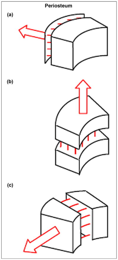
Ossification (indicated by multiple lines) in response to pulling forces: (a) from muscles applied to periosteum, (b) by lengthening, and (c) by widening. Figure adapted from Pitkin [13].
Figure 2.
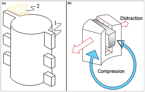
(a) Schematic view of implant with side fins “1” positioned in precut slot in bone walls “2.” Figure adapted from Pitkin et al. [28]. (b) Press-fitting of fin (“1” in (a)) to slot in bone wall results in Ilizavov type distraction (red arrows) and compression (blue arrow) due to elastic resistance of bone wall to widening.
A finite element analysis (FEA) showed the mechanical advantages of the fins in reducing the stress shielding on the distal edge of the hosting bone compared with the cylindrical implants [31]. In the FEA study, a computer-aided design model of the pylon with three pairs of fins (Figure 3) was loaded with bending moments, simulating those in the stance phase of normal gait and providing direct impact on the longevity of the implantation. The FEA demonstrated stress in the bone’s distal zone two times less than of an implant with a cylindrical shape.
Figure 3.
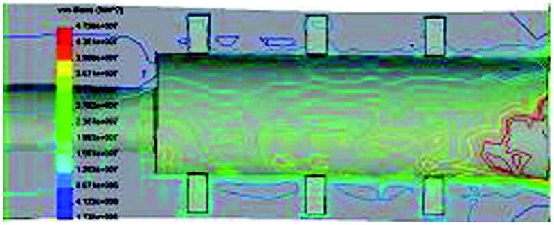
Von Mises stress distributions in skin and bone integrated pylon with fins [SBIP-3] bone-pylon system in medial-lateral cross section. Figure adapted from Pitkin et al. [30].
The current article presents the results of an animal study aimed at evaluating the process of bone reconstruction in the precut slots of the bone walls after implantation of the SBIP with side fins (SBIP-3).
METHODS
Development of Composite Porous Pylon with Side Fins (SBIP-3)
The composite porous pylon SBIP-3 manufactured for this study (Poly-Orth International) has a solid insert with a cross-shaped cross section (Figures 4 and 5). The web is 1 mm thick and 3 mm wide. The inserts were machined (Payne Engineering and Fabrication Co; Canton, Massachusetts) using 3 mm round rods (Ti6AL-4V ELI) (SmallParts; Seattle, Washington).
Figure 4.
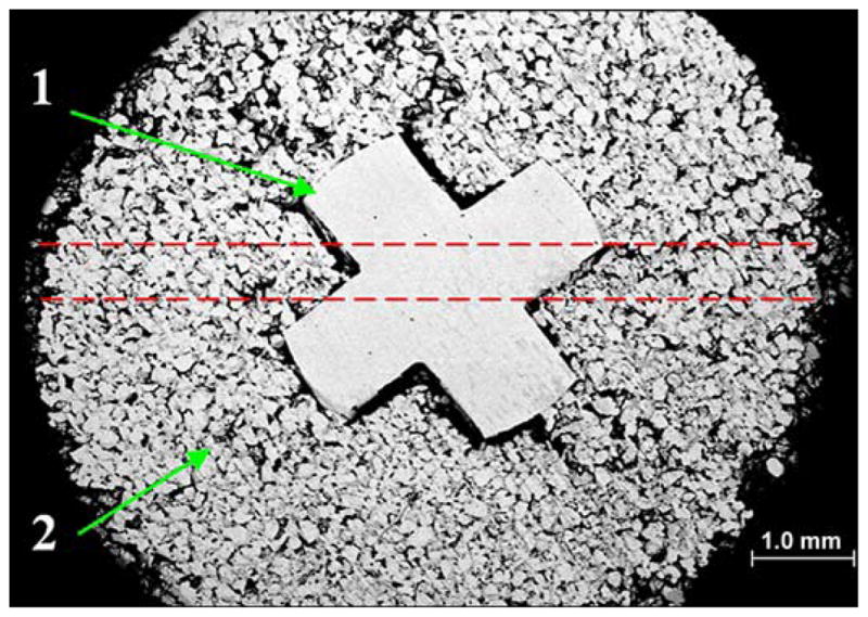
Cross section of skin and bone integrated pylon with fins (SBIP-3) with solid cross-shape insert “1” and surrounding porous cladding “2.” Sample was metallographically polished down to 6 microns. Red dashed lines show projection of 0.5 mm holes for fins (see Figure 5).
Figure 5.
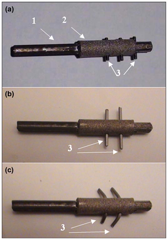
Preparation of composite porous skin and bone integrated pylon with fins (SBIP-3) for implantation. (a) pylon with solid insert “1,” porous cladding “2,” and threaded fins “3.” (b) Initial shape of wire fins “3.” (c) Final shape of wire fins “3” after bending in order to adjust to entire thickness of hosting bone walls (see Figure 4).
The molds for sintering of the pylons were fabricated by Payne Engineering and Fabrication Co, Inc, from boron nitride (Momentive; Columbus, Ohio). The solid inserts were positioned in the molds and sintered with the Ti6AL-4V ELI powder sieved to a (−80+200) mesh. Sintering was conducted by ADMA Products Group (Hudson, Ohio) for 4 hours at 1,090 °C. The porosity and pore size ranged between 45 and 50 percent and 30 and 200 μm, respectively [39]. These parameters were consistent with recommendations for better skin and bone cells adhesion, proliferation, and differentiation [40–44]. The outer diameter of the cylindrical porous cladding was 5 mm.
Holes 0.5 mm in diameter, into which the fins were to be inserted, were drilled through and perpendicularly to the longitudinal axis of the pylon, as shown with red dashed lines in Figure 4. In an embodiment shown in Figure 5(a), the fins are made from threaded studs 0.5 mm in diameter (ANITRIN; Fallbrook, California). The threads allowed the fins’ length to be adjusted to the thickness of the hosting bone (Figure 3). In an embodiment shown in Figure 2(b), the fins are made from straight pieces of wire 0.5 mm in diameter. To adjust to the thickness of the bone walls, the fins were bent (Figure 5(c)).
In Vivo Animal Experiments
Procedures
Three white New Zealand rabbits were used in the study. Two of them were treated at the Pine Acres Research Facility (Norton, Massachusetts), following Institutional Animal Care and Use Committee approval of the protocol. The third animal was treated at the I.P. Pavlov State Medical University (St. Petersburg, Russia), with all procedures approved by the ethics committee of the I.P. Pavlov University. The investigators at both of the sites used the same study protocol. The technique for amputation and the following implantation has been described previously [39]. Prior to incision, we placed a tourniquet on the rabbits’ thigh. The leg was then sterilely prepped using the usual technique. We then identified the knee joint and measured 4 cm distal to the tibial articular surface. A circumferential incision was made over the proximal tibia with a posterior skin flap to allow for tension-free closure. The muscles and tendons at this level were transected using monopolar cautery. We identified the anterior and posterior neurovascular bundles, which were then ligated and transected. Soft tissue attachments were stripped off the tibia to the level 1 cm proximal to the intended site of the osteotomy. An oscillating saw was then used to make the tibial and fibular osteotomy. The fibula was rongeured down 2 to 3 cm proximal to the level of the tibial osteotomy. Any remaining soft tissue was transected using monopolar cautery, thereby completing the amputation.
A curette was used to broach the medullary canal of the tibia. Two 2 cm longitudinal tibial slots were then made approximately 180° apart using an oscillating saw (Figure 6). A mallet was used to insert the implant into the tibial medullary canal. Prior to closure, the fat and subcutaneous tissue of the posterior skin flap was sharply excised to the level of the dermis.
Figure 6.
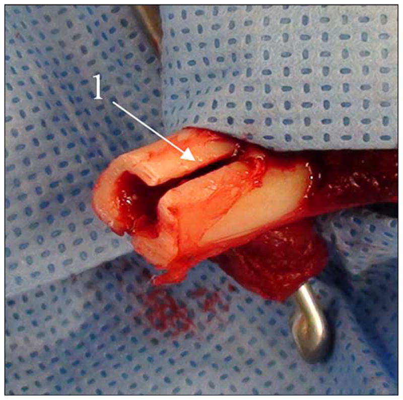
Precut of slots “1” in bone for placement of implant’s side fins.
The gastrocnemius muscle was debulked, and the wound was copiously irrigated with normal saline. A small stab incision was made in the flap using a 10 blade for the implant to exit. The dermal portion of the posterior skin flap was laid directly over and made contact with the distal end of the tibia. The wound was then closed with a 4–0 nylon suture with minimal tension. Prior to closure, special care was taken to ensure that the skin flap was in contact with the porous portion of the implant. Once closure was complete, a dry sterile dressing was placed. Position of the implant was confirmed both during and after each procedure using fluoroscopy (Figure 7).
Figure 7.
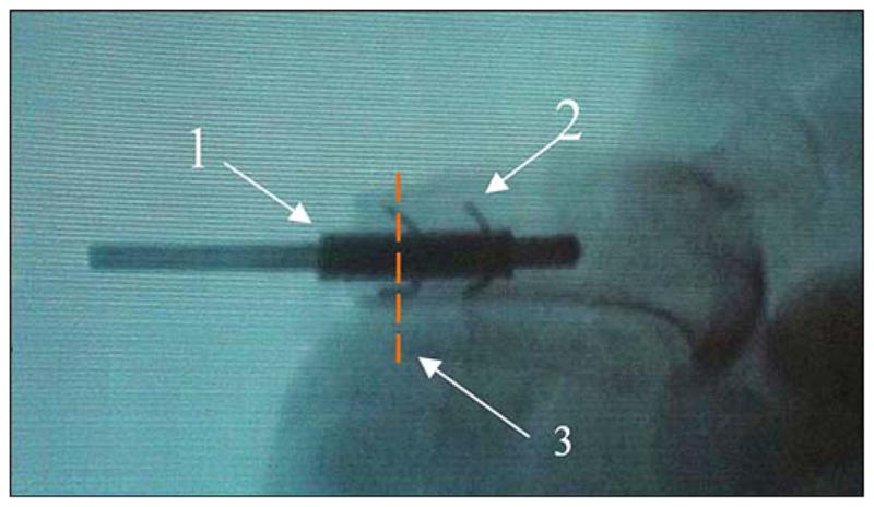
Animal 2. X-ray of pylon “1” (see Figure 5(c)) with side elements “2” after implantation to bone with the precut slots (see Figure 6). Red dashed line “3” shows plane of histology cross section (see Figure 10).
The first animal received the SBIP-3 pylon with threaded fins (Figure 5(a)), and was sacrificed after 13 weeks. After inspecting the animal, we predicted that a longer postsurgery period would be beneficial for bone remodeling. Correspondingly, animal 2 (which received the SBIP-3 pylon with bent wire fins [Figure 5(c)]) and animal 3 (which received the SBIP-3 pylon with threaded fins) were sacrificed after 26 weeks.
Histopathological Analysis
After 13 and 26 weeks from the time of implantation, respectively, animals 1 and 2 were sacrificed, and the samples were taken for histology study at the Charles River Laboratories Pathology Associates (Frederick, Maryland) [45]. The histology study was conducted by Dr. James Raymond. The plane of the cross section of the implanted pylon and the surrounding tissues is identified by dashed lines in Figure 8. The implants were processed, infiltrated, and embedded in methyl methacrylate (MMA) according to standard operating procedures. Each block was sectioned twice. One cross section perpendicular to the device, approximately 50 μm in thickness, was obtained above the device-anchoring side fins. One longitudinal section, approximately 50 μm thick, was obtained through the remaining device. Slides were scanned at 20× or 40× using an ScanScope CS (Aperio; Vista, California). All sections were obtained utilizing the Exakt system (Exakt Technologies, Inc; Oklahoma City, Oklahoma) and surface stained using hematoxylin and eosin (H&E).
Figure 8.
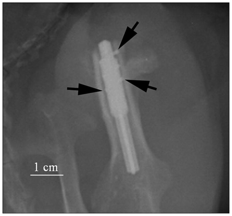
Animal 3. X-ray of implanted prosthesis (oblique view) in first week. Side fins of pylon inside bone walls are shown by black arrows. Imaging parameters of radiography were 70 kV and 8 mAs (Kodak computed radiography system).
Animal 3, like animal 2, was sacrificed after 26 weeks. A sample of the implanted femoral section was collected, fixed in 10 percent formalin, and shipped to Alizée Pathology, LLC (Thurmont, Maryland) for processing and evaluation. The femoral sample was trimmed and embedded in MMA. The block was bisected: one half was cut to generate four transverse cross-section levels per implant (bone/implant interface). All slides were stained with H&E. All resulting slides were evaluated by Serge D. Rousselle, DVM, DACVP, for inflammation (including the presence of heterophils/neutrophils, eosinophils, lymphocytes, plasma cells, macrophages, and multinucleated cells), tissue response, and general healing (fibrosis, pseudobursa, osteogenesis) [46].
Histomorphometry was performed at Alizée using Image-Pro® Plus software (Media Cybernetics, Inc; Rockville, Maryland). Morphometric analysis was performed on the longitudinal femur section. The following morphometric data were collected and analyzed: for each section, a region of interest (ROI) was selected based on guidance from the study pathologist. This ROI was bisected longitudinally into two sub-ROIs, Side A and Side B. Within each sub-ROI, the ROI area, bone area (BA), implant surface (IS), and bone-implant contact (BIC) were measured (Table).
Table.
Tabulated morphometric data for animal 3 for site 1, block 5.
| Sub-ROI | ROI (mm2) | BA (mm2) | BA (%) | BIC (mm) | IS (mm) | BIC (%) |
|---|---|---|---|---|---|---|
| A | 27.18 | 1.98 | 7.30 | 6.99 | 30.78 | 22.71 |
| B | 34.20 | 4.49 | 13.14 | 4.63 | 22.74 | 20.36 |
| Total | 61.37 | 6.48 | 10.56 | 11.62 | 53.52 | 21.71 |
BA = bone area, BIC = bone-implant contact, ROI = region of interest, IS = implant surface.
Along surfaces extending into the body of the implant but exposed to tissue, IS and BIC were measured to the depth of the porous portion of the implant.
To calculate sub-ROI or surface in each section, we summed individual measurements of a particular parameter (BA, IS, or BIC) to calculate a total value for that parameter in that region. For example, all BIC measurements in section 1–5, Side B, distal surface were summed to calculate the rTtBIC (regional total bone in contact with implant) for that specific region. The values for each parameter in each region were summed to calculate values for the entire section. Proportional values (percentages) were calculated from the parameter totals. From IS and BIC, the percentage of the IS with BIC (BIC percent) were calculated for each region by dividing the rTtBIC by the total IS for the same region and multiplying the result by 100. Images were calibrated using calibration 10× scale 4, with a ratio of 0.247 pixels per micrometer in the x- and y-axes. At this spatial calibration, linear measurements are limited to a precision of not better than 10 μm and area measurements are limited to a precision of not better than 1,000 μm2. Morphometry data are presented in the Table.
RESULTS
In animal 1, 13 weeks after implantation, complete bone regeneration healing was observed in one of the two precut slots (Figure 9). The other slot was not filled with bone cells. The magnification used to capture the image is represented in the figure legend as “×” preceded by a number (i.e., 4× is 4 times magnification).
Figure 9.
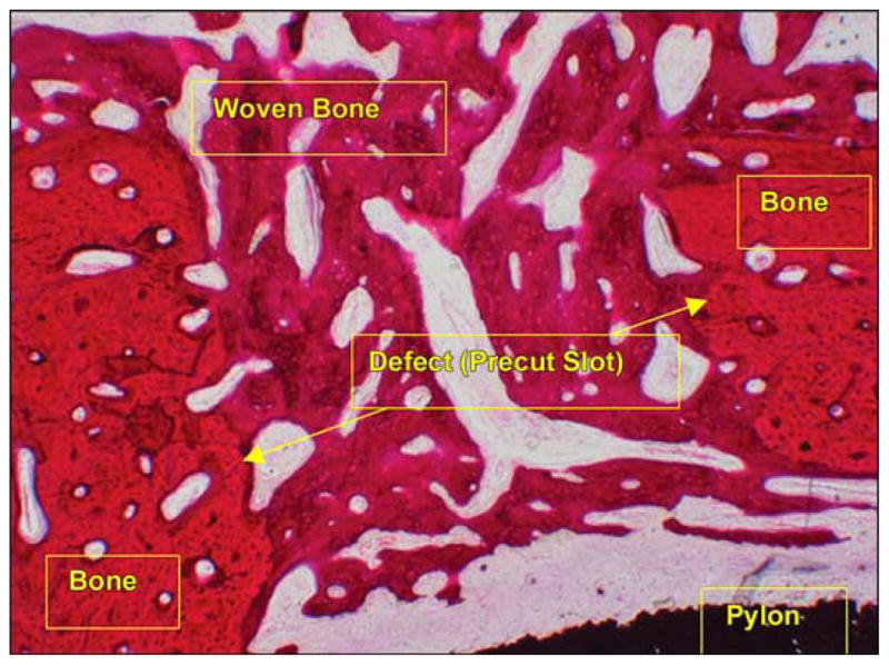
Healed precut slot (hematoxylin and eosin 4×) in animal 1. Thirteen weeks after implantation.
In animal 2, Figure 10 illustrates a photomicrograph of an individual cross section of the SBIP-3 implant and surrounding bone to demonstrate the bone-device interface. The photograph gives evidence of the ingrowth of bone and fibrovascular cells into both precut slots in the bone walls. There was no histological evidence of the precut slots in the bone in the cross section, indicating that the slots had completely healed. Minimal inflammation was observed multifocally surrounding the implant and was characterized by neutrophils and macrophages, most of which were degenerate or necrotic and admixed with cellular debris and small fragments of bone. The inflammation did not appear to extend into the implant or into the long bone. Surrounding the inflammation and cellular debris was a continuous circumferential band of fibrovascular connective tissue infiltrated by small islands of woven trabecular bone and very low numbers of inflammatory cells. In no area did the implant appear to be in direct contact with the long bone; however, endosteal bony proliferation was in very close proximity to the device in the single examined cross section. Also, there was near uniform (approximately 90%) filling of internal device pores with fibrovascular connective tissue or bone (Figure 11) and formation of blood vessels in the pores (Figure 12).
Figure 10.
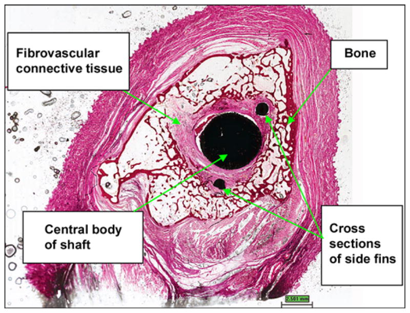
Cross section of device demonstrating bone-device interface. (hematoxylin and eosin 0.4×) in animal 2. Twenty six weeks after implantation.
Figure 11.
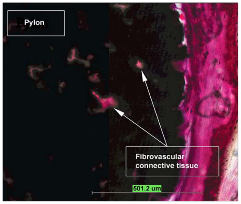
Pores filled with fibrovascular connective tissue in animal 2 (hematoxylin and eosin 10×).
Figure 12.
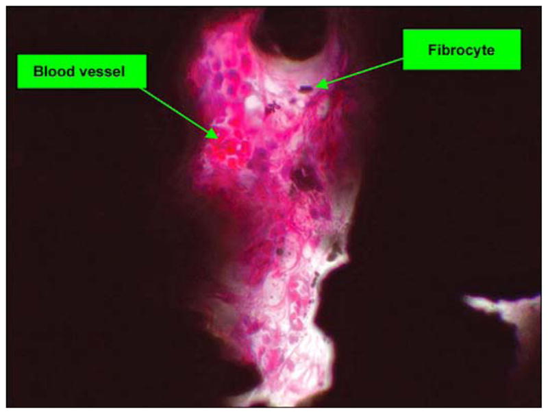
Pore with fibrovascular tissue (hematoxylin and eosin 40×) in animal 2.
In animal 3, the amputation line showed ideal bone repair characterized by complete entrapment of the device head into a newly formed ossified callus at the level of the distal fin (Figure 13). There was also direct bone apposition along the sides of the fin and the adjacent pylon surfaces as well as along the porous titanium pylon at the distal callus level (Figure 14). The body of the pylon was not in direct contact with the inner cortex proximally. However, there were sparse trabeculae of newly formed bone that occasionally crossed the gap in the two distal-most levels (in the fin area) and direct contact distally between the callus, the porous pylon, and the central crux pylon (Figure 13). The fin ends were frequently capped by directly apposed new bone trabeculae. There was no appreciable inflammatory response along the titanium pylon.
Figure 13.
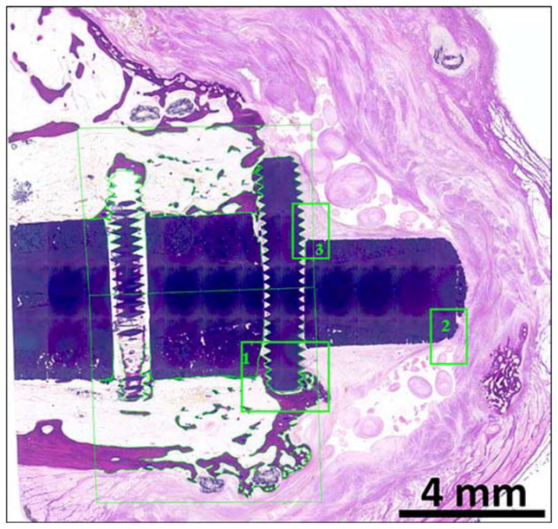
Morphometry tracings for animal 3 (hematoxylin and eosin). Tibia longitudinal cross section. Composite porous titanium skin and bone integrated pylon with fins (SBIP-3). Green boxes 1, 2, and 3 are detailed in Figures 14, 15, and 16, respectively.
Figure 14.
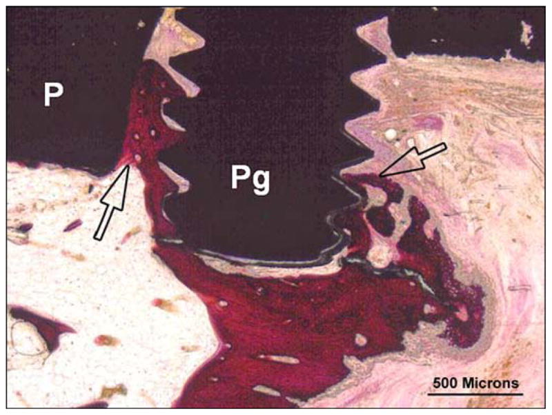
Animal 3 (hematoxylin and eosin). Composite porous titanium skin and bone integrated pylon with fins (SBIP-3). Tibia longitudinal section. Detail in green box 1 from Figure 13 (distal fin). There is extensive woven bone apposition (arrows) along exposed fin tips (Pg) binding fin to implant (P) and callus.
The very tip of the pylon was surrounded by a thin layer of fibrous connective tissue that infiltrated the polymer mesh and sat within a well-formed bursa (Figure 15). The outer most layer of the bursa was comprised of densely collagenous connective tissue with no inflammation or focal ossification; it also contained occasional weaved suture material or ties (Figure 16). The pylon remained covered by a musculo-adipose flap, and a well-differentiated bursa was formed along the tip of the pylon with no evidence of chronic trauma.
Figure 15.
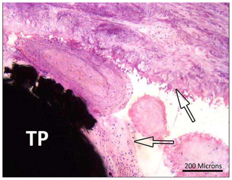
Animal 3 (hematoxylin and eosin). Composite porous titanium skin and bone integrated pylon with fins (SBIP-3). Tibia longitudinal section. Detail in green box 2 from Figure 13 (distal fin). Arrows = fibrous margins of bursa capping head of pin (TP).
Figure 16.
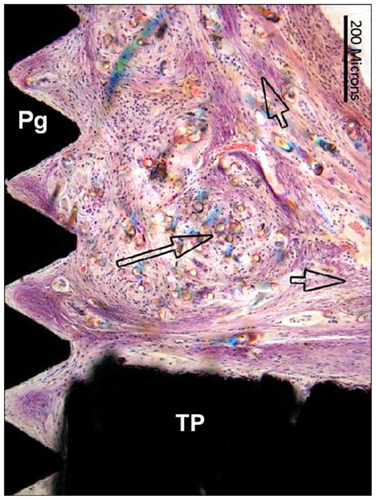
Animal 3 (hematoxylin and eosin). Tibia longitudinal section. Composite porous titanium skin and bone integrated pylon with fins (SBIP-3). Detail in green box 3 from Figure 13 (distal fin) implant (with 3 pairs of sided pegs). Short arrows = fibrous connective tissue fascicles in direct contact with head of implant (TP) and surface of fin (Pg). Long arrow = birefringent foreign polymer fibers.
Morphometry measurements showed (Table) that while relative BIC values were low, there was still good structural contact between the callus and the pylon, namely at the level of the distal fin. The sequential sections across the femur shaft showed no evidence of instability (no granulation tissue, encapsulation, or scar tissue around the pylon). There was little to no remodeling of the shaft or endosteal surface. There was no inflammatory response along the pylon.
Implantation of femoral amputation site in animal 3 showed good stability, and a stable, ossified callus that united the femoral shaft to the abutting portion of the pylons was formed. Morphometry measurements indicated a localized interface and apposition area between the callus and the distal pylon at the level of the distal fin. There was optimal biocompatibility of the devices, and no appreciable inflammatory response or encapsulation and no sequestration were found.
DISCUSSION
The outcomes of the current study are twofold: ingrowth of the surrounding cells into the pores of the implant, and regeneration of bone in the precut slots in the bone walls.
Relative to the previous report [30], we did not achieve progress in cell adhesion and proliferation. That could be caused by smaller size of the pores (80–100 μm versus 15–250 μm). Also, due to extremely thin walls of the experimental animals, we could not bore or extensively broach the medullary canal, as it is usually done in DSA, and there was a notable space between the central part of the implant and the bone walls.
With regards to the regeneration of bone in the precut slots, we obtained quite promising results. One of animal 1’s two slots was filled with the new bone, and both slots were filled with the new bone in animals 2 and 3, which had 13 additional weeks for regeneration.
Addition of the side fins to the construct of the implant activated a mechanism of circular remodeling. The longevity of an implant’s lifespan in the medullary canal depends on the eventual tightness of the ossification around the inserted shaft. In this paradigm, the vector of remodeling has to be oriented radially, inwardly to the bone’s longitudinal axis. The inward direction of remodeling occurs in dental implantation. However, as it was noted by Pitkin [13], the remodeling of the jawbone occurs differently compared with remodeling inside the medullary canal. The remodeling of the jawbone is directed toward the space occupied by the tooth or the implant. That is a natural feature of the jawbone for keeping the tooth’s root in a firm surrounding, which is used in dental implantation. As to the inward remodeling in tubular bones, it is limited by the anatomical dimensions of the medullary canal, where the marrow has to be protected from compressing. A partial inward remodeling is still possible, but only to the extent provided by the boring of the canal before insertion of the stem.
In contrast with the inward remodeling, the bone remodeling in longitudinal and circular directions is a powerful natural mechanism of self-healing, successfully used in distractional osteogenesis [36–37,47]. Thus, the pylon with the side fins (SBIP-3) was designed to utilize the concept of circular remodeling in DSA.
An additional feature of the side fins in SBIP-3 is the antirotational effect, similar to the role of transverse pins in Compress Compliant Pre-Stress technology (Biomet Orthopedics, Inc; Warsaw, Indiana) [48–49]. A distinction of the SBIP-3 approach is the activation of the Ilizarov type (distraction-compression osteogenesis) remodeling of the bone around the fins. This kind of remodeling produces stronger bone tissues [37]. In addition, the SBIP-3 techniques do not require any guiding jigs, which are necessary for inserting the antirotational Compress pins or intramedullary locked nails [49].
Due to the small number of test animals, the pull-out experiments and analysis of the postoperative risk associated with the fin’s implantation could not be conducted, but will be included in further studies.
CONCLUSIONS
In three rabbits, a pair slots were precut in the bone walls. An implant for DSA with side fins was fixated inside these slots.
Histological tests showed a complete remodeling of one slot in animal 1 at 13 weeks after the surgery, and a complete remodeling of both slots in animals 2 and 3 at 26 weeks after surgery.
Remodeling occurred despite the gap between the central part of the implant and the walls of the medullary canal.
The study was the first experimental verification of the proposal to use the mechanism of circular bone remodeling for DSA of limb prostheses.
Acknowledgments
Funding/Support: The material was based on work supported by the Eunice Kennedy Shriver National Institute of Child Health and Human Development, National Institutes of Health (grant R44HD057492). Additional funds came from the Helen and Michael Schaffer Foundation (Boston, Massachusetts).
Abbreviations
- BA
bone area
- BIC
bone-implant contact
- DSA
direct skeletal attachment
- FEA
finite element analysis
- H&E
hematoxylin and eosin
- IS
implant surface
- MMA
methyl methacrylate
- ROI
region of interest
- rTtBIC
regional total bone in contact with implant
- SBIP
skin and bone integrated pylon
- SBIP-3
SBIP with side fins
Footnotes
Author Contributions:
Study concept and supervision: M. Pitkin.
Design of implants: M. Pitkin.
Drafting of manuscript: M. Pitkin.
Surgical procedures: C. Cassidy, R. Muppavarapu, S. Shevtsov, O. Galibin.
Analysis and interpretation of preclinical data: C. Cassidy, R. Muppavarapu, J. Raymond, S. Shevtsov, O. Galibin, S. D. Rousselle.
Financial Disclosures: The authors have declared that no competing interests exist.
Disclaimer: The content is solely the responsibility of the authors and does not necessarily represent the official views of the Eunice Kennedy Shriver National Institute of Child Health and Human Development or the National Institutes of Health.
References
- 1.Brånemark R, Brånemark PI, Rydevik B, Myers RR. Osseointegration in skeletal reconstruction and rehabilitation: a review. J Rehabil Res Dev. 2001;38(2):175–81. [PubMed] [Google Scholar]
- 2.Hagberg K, Brånemark R. One hundred patients treated with osseointegrated transfemoral amputation prostheses—rehabilitation perspective. J Rehabil Res Dev. 2009;46(3):331–44. http://dx.doi.org/10.1682/JRRD.2008.06.0080. [PubMed] [Google Scholar]
- 3.Yang BC, Weng J, Li XD, Yang ZJ, Feng JM, Chen JY, Zhang XD. Preliminary study on HA coating percutaneously implanted in bone. Int J Artif Organs. 1999;22(10):713–18. [PubMed] [Google Scholar]
- 4.Smith TJ, Galm A, Chatterjee S, Wells R, Pedersen S, Parizi AM, Goodship AE, Blunn GW. Modulation of the soft tissue reactions to percutaneous orthopaedic implants. J Orthop Res. 2006;24(7):1377–83. doi: 10.1002/jor.20170. http://dx.doi.org/10.1002/jor.20170. [DOI] [PubMed] [Google Scholar]
- 5.Von Recum AF. Applications and failure modes of percutaneous devices: a review. J Biomed Mater Res. 1984;18(4):323–36. doi: 10.1002/jbm.820180403. http://dx.doi.org/10.1002/jbm.820180403. [DOI] [PubMed] [Google Scholar]
- 6.Furuzono T, Wang PL, Korematsu A, Miyazaki K, Oido-Mori M, Kowashi Y, Ohura K, Tanaka J, Kishida A. Physical and biological evaluations of sintered hydroxyapatite/silicone composite with covalent bonding for a percutaneous implant material. J Biomed Mater Res B Appl Biomater. 2003;65(2):217–26. doi: 10.1002/jbm.b.10002. http://dx.doi.org/10.1002/jbm.b.10002. [DOI] [PubMed] [Google Scholar]
- 7.Tillander J, Hagberg K, Hagberg L, Brånemark R. Osseointegrated titanium implants for limb prostheses attachments: infectious complications. Clin Orthop Relat Res. 2010;468(10):2781–88. doi: 10.1007/s11999-010-1370-0. http://dx.doi.org/10.1007/s11999-010-1370-0. [DOI] [PMC free article] [PubMed] [Google Scholar]
- 8.Hassaballa M, Mehendale S, Poniatowski S, Kalantzis G, Smith E, Learmonth ID. Subsidence of the stem after impaction bone grafting for revision hip replacement using irradiated bone. J Bone Joint Surg Br. 2009;91(1):37–43. doi: 10.1302/0301-620X.91B1.20376. http://dx.doi.org/10.1302/0301-620X.91B1.20376. [DOI] [PubMed] [Google Scholar]
- 9.Mandalia V, Eyres K, Schranz P, Toms AD. Evaluation of patients with a painful total knee replacement. J Bone Joint Surg Br. 2008;90(3):265–71. doi: 10.1302/0301-620X.90B3.20140. http://dx.doi.org/10.1302/0301-620X.90B3.20140. [DOI] [PubMed] [Google Scholar]
- 10.Kawamura H, Dunbar MJ, Murray P, Bourne RB, Rorabeck CH. The porous coated anatomic total hip replacement. A ten to fourteen-year follow-up study of a cementless total hip arthroplasty. J Bone Joint Surg Am. 2001;83-A(9):1333–38. [PubMed] [Google Scholar]
- 11.Berend ME, Ritter MA, Meding JB, Davis P. Twenty-one years clinical experience of 461 femoral revision total hip arthroplasties with a calcar replacement prosthesis. The Duke Orthop J. 2012;2(1):1–4. http://dx.doi.org/10.5005/jp-journals-10017-1010. [Google Scholar]
- 12.Frossard LA, Tranberg R, Haggstrom E, Pearcy M, Brånemark R. Load on osseointegrated fixation of a transfemoral amputee during a fall: loading, descent, impact and recovery analysis. Prosthet Orthot Int. 2010;34(1):85–97. doi: 10.3109/03093640903585024. http://dx.doi.org/10.3109/03093640903585024. [DOI] [PubMed] [Google Scholar]
- 13.Pitkin M. One lesson from arthroplasty to osseointegration in search for better fixation of in-bone implanted prosthesis. J Rehabil Res Dev. 2008;45(4):vii–xiv. [PMC free article] [PubMed] [Google Scholar]
- 14.Helgason B, Pálsson H, Rúnarsson TP, Frossard L, Viceconti M. Risk of failure during gait for direct skeletal attachment of a femoral prosthesis: a finite element study. Med Eng Phys. 2009;31(5):595–600. doi: 10.1016/j.medengphy.2008.11.015. http://dx.doi.org/10.1016/j.medengphy.2008.11.015. [DOI] [PubMed] [Google Scholar]
- 15.Huiskes R, Weinans H, van Rietbergen B. The relationship between stress shielding and bone resorption around total hip stems and the effects of flexible materials. Clin Orthop Relat Res. 1992;(274):124–34. [PubMed] [Google Scholar]
- 16.Rosenbaum Chou TG, Child JR, Naughtin RJ, Rigdon RR, Schumann C, Bloebaum RD. The relationship between femoral periprosthetic cortical bone geometry and porosity after total hip arthroplasty. J Biomed Mater Res A. 2008;87(1):107–15. doi: 10.1002/jbm.a.31702. http://dx.doi.org/10.1002/jbm.a.31702. [DOI] [PubMed] [Google Scholar]
- 17.Tomaszewski PK, van Diest M, Bulstra SK, Verdonschot N, Verkerke GJ. Numerical analysis of an osseointegrated prosthesis fixation with reduced bone failure risk and periprosthetic bone loss. J Biomech. 2012;45(11):1875–80. doi: 10.1016/j.jbiomech.2012.05.032. http://dx.doi.org/10.1016/j.jbiomech.2012.05.032. [DOI] [PubMed] [Google Scholar]
- 18.Nebergall A, Bragdon C, Antonellis A, Kärrholm J, Brånemark R, Malchau H. Stable fixation of an osseointegated implant system for above-the-knee amputees: titel RSA and radiographic evaluation of migration and bone remodeling in 55 cases. Acta Orthop. 2012;83(2):121–28. doi: 10.3109/17453674.2012.678799. http://dx.doi.org/10.3109/17453674.2012.678799. [DOI] [PMC free article] [PubMed] [Google Scholar]
- 19.Frossard L, Stevenson N, Sullivan J, Uden M, Pearcy M. Categorization of activities of daily living of lower limb amputees during short-term use of a portable kinetic recording system: A preliminary study. J Prosthet Orthot. 2011;23(1):2–11. http://dx.doi.org/10.1097/JPO.0b013e318207914c. [Google Scholar]
- 20.Lee WC, Frossard LA, Hagberg K, Haggstrom E, Gow DL, Gray S, Brånemark R. Magnitude and variability of loading on the osseointegrated implant of transfemoral amputees during walking. Med Eng Phys. 2008;30(7):825–33. doi: 10.1016/j.medengphy.2007.09.003. http://dx.doi.org/10.1016/j.medengphy.2007.09.003. [DOI] [PubMed] [Google Scholar]
- 21.Pitkin M, Raykhtsaum G, inventors. United States patent US 8,257,435. Skin integrated device. 2012 Sep 4;
- 22.Pitkin M, Blinova MI, Yudintseva NV, Potokin IL, Raykhtsaum G, Pinaev GP. Skin and bone integrated prosthetic technology. I. Characterization and morphology of human cells cultivated on titanium implants of different structures [abstract]. Proceedings of the 9th Russian National Congress, People and Health; 2004 Nov 22–26; St. Petersburg, Russia. St. Petersburg: Russina National Congress; 2004. p. 217. [Google Scholar]
- 23.Shelton TJ, Beck JP, Bloebaum RD, Bachus KN. Percutaneous osseointegrated prostheses for amputees: Limb compensation in a 12-month ovine model. J Biomech. 2011;44(15):2601–06. doi: 10.1016/j.jbiomech.2011.08.020. http://dx.doi.org/10.1016/j.jbiomech.2011.08.020. [DOI] [PMC free article] [PubMed] [Google Scholar]
- 24.Aschoff HH, Kennon RE, Keggi JM, Rubin LE. Transcutaneous, distal femoral, intramedullary attachment for above-the-knee prostheses: an endo-exo device. J Bone Joint Surg Am. 2010;92(Suppl 2):180–86. doi: 10.2106/JBJS.J.00806. http://dx.doi.org/10.2106/JBJS.J.00806. [DOI] [PubMed] [Google Scholar]
- 25.Kang NV, Pendegrass C, Marks L, Blunn G. Osseocutaneous integration of an intraosseous transcutaneous amputation prosthesis implant used for reconstruction of a transhumeral amputee: case report. J Hand Surg Am. 2010;35(7):1130–34. doi: 10.1016/j.jhsa.2010.03.037. http://dx.doi.org/10.1016/j.jhsa.2010.03.037. [DOI] [PubMed] [Google Scholar]
- 26.Pitkin M. Design features of implants for direct skeletal attachment of limb prostheses. J Biomed Mater Res A. 2013 Apr 2; doi: 10.1002/jbm.a.34606. Published online April 2, 2013. http://dx.doi.org/10.1002/jbm.a.34606. [DOI] [PMC free article] [PubMed]
- 27.Pitkin M, Raykhtsaum G, Galibin OV, Protasov MV, Chihovskaya JV, Belyaeva IG. Skin and bone integrated prosthetic pylon: a pilot animal study. J Rehabil Res Dev. 2006;43(4):573–80. doi: 10.1682/jrrd.2005.05.0160. http://dx.doi.org/10.1682/JRRD.2005.05.0160. [DOI] [PMC free article] [PubMed] [Google Scholar]
- 28.Pitkin M, Raykhtsaum G, Pilling J, Galibin OV, Protasov MV, Chihovskaya JV, Belyaeva IG, Blinova MI, Yudintseva NM, Potokin IL, Pinaev GP, Moxson V, Duz V. Porous composite prosthetic pylon for integration with skin and bone. J Rehabil Res Dev. 2007;44(5):723–38. doi: 10.1682/jrrd.2006.12.0160. http://dx.doi.org/10.1682/JRRD.2006.12.0160. [DOI] [PMC free article] [PubMed] [Google Scholar]
- 29.Farrell BJ, Prilutsky BI, Ritter JM, Kelley S, Popat K, Pitkin M. Effects of pore size, implantation time, and nano-surface properties on rat skin ingrowth into percutaneous porous titanium implants. J Biomed Mater Res A. 2013 May 23; doi: 10.1002/jbm.a.34807. http://dx.doi.org/10.1002/jbm.a.34807. [DOI] [PMC free article] [PubMed]
- 30.Pitkin M, Raykhtsaum G, Pilling J, Shukeylo Y, Moxson V, Duz V, Lewandowski J, Connolly R, Kistenberg RS, Dalton JF, 4th, Prilutsky B, Jacobson S. Mathematical modeling and mechanical and histopathological testing of porous prosthetic pylon for direct skeletal attachment. J Rehabil Res Dev. 2009;46(3):315–30. doi: 10.1682/jrrd.2008.09.0123. http://dx.doi.org/10.1682/JRRD.2008.09.0123. [DOI] [PMC free article] [PubMed] [Google Scholar]
- 31.Pitkin M, Pilling J, Raykhtsaum G. Mechanical properties of totally permeable titanium composite pylon for direct skeletal attachment. J Biomed Mater Res B Appl Biomater. 2012;100(4):993–99. doi: 10.1002/jbm.b.32663. http://dx.doi.org/10.1002/jbm.b.32663. [DOI] [PMC free article] [PubMed] [Google Scholar]
- 32.Liu X, Wu S, Yeung KW, Chan YL, Hu T, Xu Z, Liu X, Chung JC, Cheung KM, Chu PK. Relationship between osseointegration and superelastic biomechanics in porous NiTi scaffolds. Biomaterials. 2011;32(2):330–38. doi: 10.1016/j.biomaterials.2010.08.102. http://dx.doi.org/10.1016/j.biomaterials.2010.08.102. [DOI] [PubMed] [Google Scholar]
- 33.Navarro M, Michiardi A, Castaño O, Planell JA. Biomaterials in orthopaedics. J R Soc Interface. 2008;5(27):1137–58. doi: 10.1098/rsif.2008.0151. http://dx.doi.org/10.1098/rsif.2008.0151. [DOI] [PMC free article] [PubMed] [Google Scholar]
- 34.Pitkin M, inventor. US patent application 11/899068. In-bone implantable shaft for prosthetic joints or for direct skeletal attachment of external limb prostheses and method of its installation. 2007
- 35.Pitkin M. On the way to total integration of prosthetic pylon with residuum. J Rehabil Res Dev. 2009;46(3):345–60. doi: 10.1682/jrrd.2008.08.0112. http://dx.doi.org/10.1682/JRRD.2008.08.0112. [DOI] [PMC free article] [PubMed] [Google Scholar]
- 36.Ilizarov GA. The principles of the Ilizarov method. Bull Hosp Jt Dis Orthop Inst. 1988;48(1):1–11. [PubMed] [Google Scholar]
- 37.Ilizarov GA. The tension-stress effect on the genesis and growth of tissues. Part I. The influence of stability of fixation and soft-tissue preservation. Clin Orthop Relat Res. 1989;238:249–81. [PubMed] [Google Scholar]
- 38.Pitkin M, Shevtsov M, Yudentsova N, Blinova M, Pinaev G, Potokin I, Protasov M, Suslov D, Ivanova A, Savchenko O, Galibin O. Application of the basic principle of distraction osteogenesis to in-bone implantation. Proceedings of 4th International Conference on Advances in Orthopaedic Osseointegration; 2012 Feb 10–12; San Francisco, CA. Orthopaedic Surgical Osseointegration Society; 2012. p. 23. [Google Scholar]
- 39.Pitkin M, Cassidy C, Muppavarapu R, Edell D. Recording of electric signal passing through a pylon in direct skeletal attachment of leg prostheses with neuromuscular control. IEEE Trans Biomed Eng. 2012;59(5):1349–53. doi: 10.1109/TBME.2012.2187784. http://dx.doi.org/10.1109/TBME.2012.2187784. [DOI] [PMC free article] [PubMed] [Google Scholar]
- 40.Clemow AJ, Weinstein AM, Klawitter JJ, Koeneman J, Anderson J. Interface mechanics of porous titanium implants. J Biomed Mater Res. 1981;15(1):73–82. doi: 10.1002/jbm.820150111. http://dx.doi.org/10.1002/jbm.820150111. [DOI] [PubMed] [Google Scholar]
- 41.Blinova MI, Yudintzeva NM, Nikolaenko NS, Potokin IL, Raykhtsaum G, Pitkin MR, Pinaev GP. Cell cultivation on porous titanium implants with various structures. Cell Tissue Biol. 2010;4(6):572–79. doi: 10.1134/S1990519X10060088. http://dx.doi.org/10.1134/S1990519X10060088. [DOI] [PMC free article] [PubMed] [Google Scholar]
- 42.El Sayegh TY, Pilliar RM, McCulloch CA. Attachment, spreading, and matrix formation by human gingival fibroblasts on porous-structured titanium alloy and calcium poly-phosphate substrates. J Biomed Mater Res. 2002;61(3):482–92. doi: 10.1002/jbm.10217. http://dx.doi.org/10.1002/jbm.10217. [DOI] [PubMed] [Google Scholar]
- 43.Itälä AI, Ylänen HO, Ekholm C, Karlsson KH, Aro HT. Pore diameter of more than 100 microm is not requisite for bone ingrowth in rabbits. J Biomed Mater Res. 2001;58(6):679–83. doi: 10.1002/jbm.1069. http://dx.doi.org/10.1002/jbm.1069. [DOI] [PubMed] [Google Scholar]
- 44.Cheung S, Gauthier M, Lefebvre LP, Dunbar M, Filiaggi M. Fibroblastic interactions with high-porosity Ti-6Al-4V metal foam. J Biomed Mater Res B Appl Biomater. 2007;82(2):440–49. doi: 10.1002/jbm.b.30749. http://dx.doi.org/10.1002/jbm.b.30749. [DOI] [PubMed] [Google Scholar]
- 45.Raymond J. Summary of histopathologic evaluation of titanium pylon devices implanted in two rabbits for Poly-Orth International. Frederick (MD): Charles River Pathology Associates; 2010. Report No.:20006108. [Google Scholar]
- 46.Rousselle SD. Executive summary for Poly-Orth International. Thurmont (MD): Alizée Pathology, LLC; 2012. Skin-bone implant interface. Project FEE12–312. [Google Scholar]
- 47.Ilizarov GA. The tension-stress effect on the genesis and growth of tissues: Part II. The influence of the rate and frequency of distraction. Clin Orthop Relat Res. 1989;(239):263–85. [PubMed] [Google Scholar]
- 48.Pedtke AC, Wustrack RL, Fang AS, Grimer RJ, O’Donnell RJ. Aseptic failure: how does the Compress(®) implant compare to cemented stems? Clin Orthop Relat Res. 2012;470(3):735–42. doi: 10.1007/s11999-011-2159-5. http://dx.doi.org/10.1007/s11999-011-2159-5. [DOI] [PMC free article] [PubMed] [Google Scholar]
- 49.Kempf I, Leung KS, Grosse A. Practice of intramedullary locked nails. New York: Springer; 2002. [Google Scholar]


