Abstract
Motion capture is usually performed on only a few steps of over-ground locomotion, limited by the finite sensing volume of most capture systems. This makes it difficult to evaluate walking over longer distances, or in a natural environment outside the laboratory. Here we show that motion capture may be performed relative to a mobile platform, such as a wheeled cart that is moved with the walking subject. To determine the person’s absolute displacement in space, the cart’s own motion must be localized. We present three localization methods and evaluate their performance. The first detects cart motion solely from the relative motion of the subject’s feet during walking. The others use sensed motion of the cart’s wheels to perform odometry, with and without an additional gyroscope to enhance sensitivity to turning about the vertical axis. We show that such methods are practical to implement, and with present-day sensors can yield accuracy of better than 1% over arbitrary distances.
Introduction
Motion capture of human locomotion is usually limited to a finite space, whose volume is defined by a set of fixed cameras or other sensors. This makes it difficult to characterize some activities, such as unsteady or unconstrained walking. Treadmills function well for steady, continuous walking, but not for significant changes in speed or direction. Motion captured over-ground for large distances could facilitate the study of a greater range of activities than currently possible.
An alternative is to fix the sensors to a wheeled cart that is moved to accompany the human subject. This allows for measurement of the subject’s motion relative to the ground, if the cart’s absolute displacement can be estimated. For human walking, one such indicator of cart motion is the relative position of foot-mounted motion capture markers. Assuming that there is always one foot at rest on the ground, at least one marker will indicate cart motion [1]. An alternative is to use odometry, referring to path integration of the cart’s velocity as sensed from its wheels [2]. We previously used a combination of these methods to measure step variability [1], and could capture 100 or more contiguous steps during straight walking. Changes in walking direction can, however, reduce accuracy due to slippage between between feet or wheels with ground. Fortunately, adding a gyroscope can correct for such issues [3].
The methods above are standard in the field of mobile robots, but are subject to trade-offs in performance and complexity. They have yet to be assessed in the context of human motion capture. In the present study, we have implemented and tested all three methods: foot-based sensing, wheel-only odometry, and gyroscope-enhanced odometry. We also present techniques for quantifying accuracy and offer suggestions for addressing common practical issues. This may facilitate motion capture over distances longer than practical in the laboratory.
Methods
We implemented three methods of long-distance motion capture, and tested them for overground walking. The hardware consisted of a cart-mounted motion capture system for sensing the person in three dimensions, and optical encoders and a gyroscope for sensing the motion of the cart (see Figure 1). We first present the foot-referenced method, which was assessed along straight-line walking. This is followed by two odometry methods, one based on sensing of the cart’s wheels, and the other adding a gyroscope for yaw rotation. Details regarding sensors and methodology can be found in Supplementary Material A.
Figure 1.
System for collecting overground walking data. Motion capture cart is pushed behind the walking subject, recording marker paths relative to the cart. On-board sensors (encoders and gyro) and 3-dimensional marker data are then used to determine marker paths relative to ground.
Foot-referenced Estimation of Cart Motion
Motion of the cart may be determined solely from the relative motion of foot-mounted markers. During walking, the stance legs alternate, so that at least one foot is stationary on the ground at all times [1]. One of the principal challenges is to identify which marker is stationary on the ground, based on markers alone. During walk, we assume that each foot is always either stationary or moving only forward in space. If the cart moves forward, a foot on the ground will have a marker moving backwards relative to the cart. Therefore the marker with most rearward velocity therefore indicates which foot is stationary. Two main limitations of this method are that it does not capture changes in cart heading, and is not suitable for running gaits. This method is termed Leap-Frog localization [4] in cooperative robotic applications, referring to alternation between stationary reference points.
This method is highly dependent on marker placement on the foot. For optical motion capture, it was necessary to mount markers on the heels of the feet for line of sight. These locations are challenging to track because the heel comes to rest very briefly during each step, and heelstrike induces vibrations of the foot, shoe, and marker. An alternative is to use magnetism-based markers that do not require line of sight (e.g., Ascension Technologies, Inc.; Burlington, VT.), mounted atop the foot insteps [1]. That location is relatively motionless during much of the stance.
The cart speed can be estimated from the displacement of whichever foot is stationary. Given a sequence of forward displacements for the left and right feet (dl and dr respectively), the cart forward speed v can be computed as the difference between two consecutive measurements, using whichever foot shows the smaller motion in the moving capture frame:
| (1) |
where T is sample period. Cart speed v has opposite sign to the marker displacements, which are moving backwards relative to the cart, hence the negative sign in the Eq. 1. A similar equation may be applied for backward cart motion. The x direction is defined as forward for the cart, and the y (lateral) direction is not measured (Figure 1). Forward position is updated according to
| (2) |
The estimated cart speed can be corrupted by missing or occluded marker data. We address this problem by filtering the cart speed using a Kalman filter (see Supplementary Material B for details).
Wheel-based Odometry
We also implemented an estimate of the cart’s motion from wheel encoders. This method does not depend on the nature of the subject’s footsteps, and therefore applies even when the feet slip on the ground or have an aerial phase. Here, the primary assumption is that the wheels roll a fixed distance per revolution, without slipping on the ground. This is a form of dead-reckoning, based on the integral of wheel motion.
We measured wheel rotation with optical encoders located on the rear wheels of the cart. The encoder count change during a sample period el and er, can be translated into left and right wheel forward displacements (sl and sr respectively), using information about wheel diameter D and the count-per-revolution C specification of the encoders
| (3) |
These data may be used to track cart motion in the ground plane. Given a separation between wheels B and the wheel linear displacement, the cart displacement (x forward, y lateral, and ψ yaw rotation or heading, defined relative to an initial configuration) is updated according to
| (4) |
Additional details can be found in Supplementary Material C.
Gyroscope Enhanced Odometry
For conditions such as walking around corners, the cart’s yaw rotation may be estimated more accurately with a gyroscope, which senses angular velocity without being affected by external conditions. We integrate the gyro sensor output ω over time to estimate relative cart heading (with respect to the starting pose). Position and heading are computed as
| (5) |
The heading estimate from the gyroscope could be improved by fusing it with encoder data using estimation techniques (i.e. Kalman filters). However, the benefits are minimal when using a low-drift and well-calibrated gyroscope as in our case [3], and as discussed previously by others [5].
Experimental Results
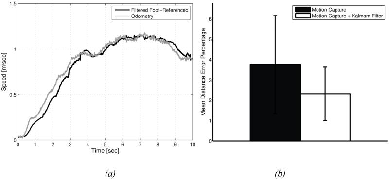
For the foot-referenced method, we measured straight-line walking and evaluated the forward displacement errors for a foot-mounted marker. We performed 20 straight walk experiments (N = 20), each a known distance of 20 m (L = 20). The average error (Eq. 6) for our implementation of foot-referencing was 3.8%, which was reduced to 2.7% with the digital filter (see Figure 2).
| (6) |
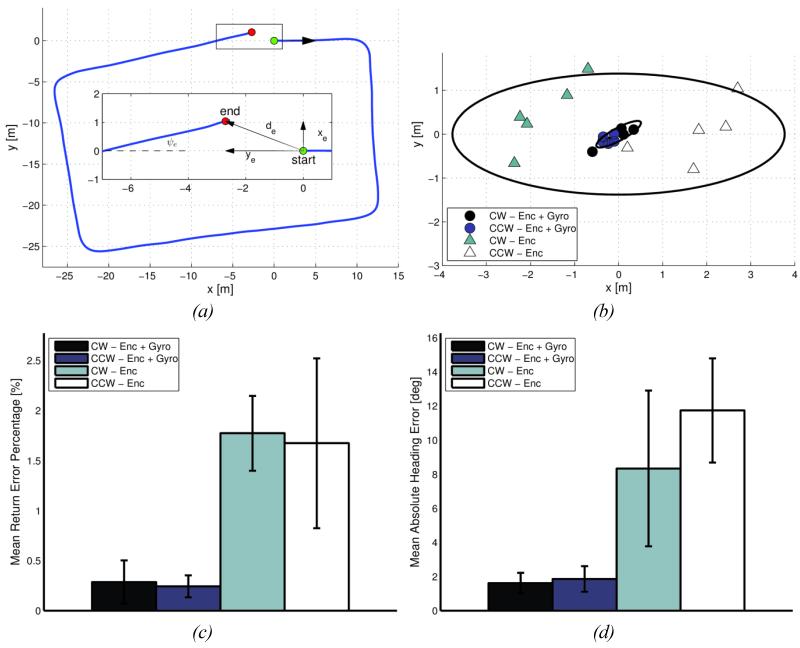
We tested the encoder-based odometry methods with known closed walking paths. Here, an experimenter pushed the cart following a subject walking a rectangular path about 112 m in length (in a 36 m by 20 m corridor grid), with identical starting and ending points in the middle of one side. This path was repeated five times, both clockwise and counter-clockwise, to quantify errors in both directions. The results are presented as position, distance and heading errors (xe, ye, de and ψe), defined as the deviation of the estimated ending configuration from actual over a closed path that ends on its starting point (see Figure 3a and Eqs. 7 and 8).
Figure 2.
Forward cart speed and displacement errors for the foot-referenced method. (a) Estimate of cart speed from foot-referenced markers after filtering. A Kalman filter reduces noise, yielding cart speeds (black line) comparable to estimates from wheel encoders (gray line), albeit with a small time lag that can be removed with post-processing. (b) Applied to straight line walking of 20 m, errors are shown as mean percentages (with error bars representing s.d.).
Figure 3.
Comparison of positioning and heading errors using odometry-based methods for cart localization. (a) Example of cart path estimated using wheel odometry. Magnified view of the return point (inset) is shown with definitions of the final position (xe and ye), distance (de), and heading (ψe) errors. (b) Position errors after a closed path returning to the starting point, using wheel-based odometry alone, and with gyroscope enhancement. Data are for clockwise and counter-clockwise paths (CW and CCW, respectively), one data point per trial. Ellipses indicate 2σ covariance error. (c) Magnitude of position error (), expressed as a percentage of the traveled distance. (d) Average absolute heading error () across trials. Error bars indicate s.d.
| (7) |
| (8) |
We estimated the average return positioning errors for both wheel-based methods (Figure 3b). The error is presented as percentage of distance traveled and is approximated using the nominal path length (L ≈ 112). For wheel-based odometry alone, the error was 1.7% (0.62 s.d.) of the traveled distance, across all ten experiments (N = 10). Adding gyroscope measurements, the error was reduced to 0.3% (0.16 s.d.) (Figure 3c). The average of the absolute heading error (Eq. 9) was 10 deg (4.07 s.d.) using odometry alone and 1.7 deg (1.19 s.d.) with the gyroscope (see Figure 3d). Because the wheel-based odometry errors are dominated by heading errors, the inclusion of gyroscope improves performance, subject to, the quality of the gyroscope [3].
Finally, we quantified the extra noise introduced by cart motion. We used the moving cart to collect position data of a stationary object. Those data were high-pass filtered to focus on vibration-induced noise, yielding standard deviations of up to 2.27 mm, as opposed to 0.024 mm with the cart not moving. The increased errors can be caused by imperfect wheels, uneven floor surfaces and small relative motion of the cameras with respect to the cart.
Discussion
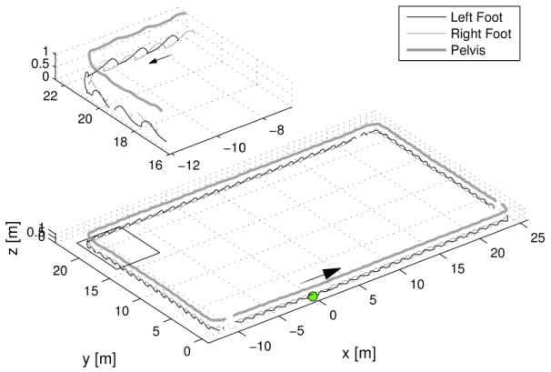
Our goal was to capture human locomotion over long distances. We mounted a motion capture system on a mobile cart, which must then be localized to a stationary reference. We evaluated three localization methods using differing numbers of sensors. We found that localization may be performed from foot-mounted markers alone, but only if there is always at least one foot on ground, and for relatively straight paths. Wheel-based odometry can improve accuracy considerably, but less so for paths with turns. Not surprisingly, we found that the method using the most information—gyroscope-enhanced odometry—yielded the best accuracy. This works with any gait and on paths that involve turns (see Figure 4).
Figure 4.
Sample motion capture data for overground walking, using gyroscope-enhanced odometry. Markers for left and right feet and pelvis are shown (thin black, thin gray and thick black lines respectively). The marker motion with respect to the cart is added to the estimated cart motion to yield locations relative to ground. Example of a closed rectangular path about 112 m in length. Also shown is a magnified view of data taken while turning a corner.
Although foot-referenced localization can yield acceptable accuracy [1], its implementation is not trivial. The method requires overlapping intervals where foot-mounted markers are stationary. It is affected by marker vibrations, which often increase with walking speed. Vibrations may be partially offset with an appropriate noise filter.
The addition of wheel sensing facilitates straightforward implementation of odometry. We obtain best accuracy by calibrating scaling factors from empirical data gathered over known distances, rather than from wheel geometry. We caution that any calibration is specific to a particular floor surface, because wheel slippage and deformation depend on ground contact conditions. Where turning paths are involved, wheel-based odometry performs less well. However, the addition of a yaw gyroscope can greatly improve performance and reduce the impact of wheel slippage. Even though these methods allow the cart to be localized on the ground plane, the motion capture is performed in three dimensions. Although these various sources for error tend to degrade absolute accuracy in space, we believe that the relative (displacement) accuracy can be quite acceptable for many biomechanical applications.
The methods presented tend to share and often magnify the limitations of conventional motion capture. With a cart, markers may usually be tracked on one side of the body, and are subject to occlusion, loss of view, and poor depth accuracy (along the camera axis). It may be challenging to maintain line of sight, especially when turning corners (see Figure 4). Accuracy may be degraded with poor camera views or long capture distances. Some of these restrictions are reduced by using a magnetic tracker, but many can be reduced with multiple cameras, placed appropriately.
Mobile motion tracking is necessarily subject to increasing drift over time. For closed paths, a possible compensation is to distribute the error over the entire trajectory so that the start and end points match correctly. It may also help to provide additional absolute reference information, for example with fiducials, meaning markers fixed at known ground locations. Another issue is vibration of the cart, which is increased by rough or deformable terrain, might be reduced by rolling a dolly on a smooth track. We have yet to evaluate such possibilities.
The natural alternative for over-ground locomotion is traditional motion capture with many cameras fixed to ground. But even then it may be difficult to calibrate for absolute accuracy over large capture volumes, especially if many cameras have non-overlapping views. Fortunately, many human walking studies require only relative displacement (e.g., joint angles or step lengths) rather than absolute position. We believe that mobile motion capture can yield good accuracy over distances longer than practical with many other methods, albeit with limitations imposed by the need for cart localization.
Supplementary Material
Table of Symbols
- T
Sampling period
- L
Traveled distance
- dl, dr
Left and right foot displacement relative to cart, measured with motion capture system
- v
Estimated foot-referenced cart speed
- D
Wheel diameter
- C
Encoder count-per-revolution parameter
- B
Cart wheel separation or base
- el, er
Left and right wheel encoder outputs
- sl, sr
Left and right wheel displacement
- x, y
Cart position relative to the origin
- xe, ye
Cart return positioning error
Average forward percentage error
- ψ
Cart heading angle
- ψe
Cart return heading error
Average of the absolute return heading error
- ω
Gyroscope output
- de
Return distance error
Average position percentage error
Footnotes
Publisher's Disclaimer: This is a PDF file of an unedited manuscript that has been accepted for publication. As a service to our customers we are providing this early version of the manuscript. The manuscript will undergo copyediting, typesetting, and review of the resulting proof before it is published in its final citable form. Please note that during the production process errors may be discovered which could affect the content, and all legal disclaimers that apply to the journal pertain.
Conflict of Interest Disclosure
We authors wish to confirm there are no known conflicts of interest associated with this publication.
References
- 1.Bauby CE, Kuo AD. Active control of lateral balance in human walking. Journal of Biomechanics. 2000;33:1433–1440. doi: 10.1016/s0021-9290(00)00101-9. [DOI] [PubMed] [Google Scholar]
- 2.Kelly A. Linearized Error Propagation in Odometry. International Journal of Robotics Research. 2004;23:179–218. [Google Scholar]
- 3.Chung H, Ojeda L, Borenstein J. Accurate Mobile Robot Dead-reckoning With a Precision-calibrated Fiber Optic Gyroscope. IEEE Transactions on Robotics and Automation. 2001;17(1):80–84. [Google Scholar]
- 4.Tully S, Kantor G, Choset H. Leap-Frog Path Design for Multi-Robot Cooperative Localization, Field and Service Robotics, Springer Tracts in Advanced Robotics. 2009;62:307–317. [Google Scholar]
- 5.Ojeda L, Chung H, Borenstein J. Precision Calibration of Fiber-optics Gyroscopes for Mobile Robot Navigation; Proceedings of the 2000 IEEE International Conference on Robotics and Automation; San Francisco, CA. 2000.pp. 2064–2069. [Google Scholar]
Associated Data
This section collects any data citations, data availability statements, or supplementary materials included in this article.


