Abstract
For passive sheathless particles focusing in microfluidics, the equilibrium positions of particles are typically controlled by micro channels with a V-shaped obstacle array (VOA). The design of the obstacles is mainly based on the distribution of flow streamlines without considering the existence of particles. We report an experimentally verified particle trajectory simulation using the arbitrary Lagrangian-Eulerian (ALE) fluid-particle interaction method. The particle trajectory which is strongly influenced by the interaction between the particle and channel wall is systematically analyzed. The numerical experiments show that the streamline is a good approximation of particle trajectory only when the particle locates on the center of the channel in depth. As the advantage of fluid-particle interaction method is achieved at a high computational cost and the streamline analysis is complex, a heuristic dimensionless design objective based on the Faxen's law is proposed to optimize the VOA devices. The optimized performance of particle focusing is verified via the experiments and ALE method.
INTRODUCTION
Micro-sized particle focusing is a standard step for biological processing in microfluidics.1 The focusing devices can be categorized as either the active type that uses externally induced forces,2, 3, 4, 5, 6, 7, 8, 9, 10, 11, 12, 13 or the passive type that typically uses the hydrodynamic fluid effects.14, 15, 16, 17, 18, 19, 20, 21, 22, 23, 24 Because of the advantages on the simple structure, potential for integration, label free, and biology compatibility, many passive focusing effects have been used in microfluidic devices, such as the sheath flow effect, the hydrodymatic effect,25, 26 the inertial and dean effect,20, 21, 22, 23, 24, 27 the hydrophoretic effect,15, 16 etc. The sheath flow method requires more than one input flow at the inlet port and a relatively accurate flow control in order to push the flow with particles existing in the specified position of microfluidic channel. Therefore, the disturbance of the pump will influence the focusing efficiency. The inertial effect and dean effect of a fluid, which induces the particle-particle interaction and/or particle-wall interaction, requires a high flow rate in order to enhance the effect of particle focusing in the channel. Because of the requirement of a high flow rate (in most cases above 1 m/s, which is comparatively high in microfluidic systems), it is difficult to use a real-time probe, and the manufacturing requirements are high.27 The hydrophoresis focusing method generates focusing phenomena by channel's structure, leading to less sensitivity to flow rate, and an enhanced efficiency of focusing in the point.15, 16
The design of the hydrophoretic particle focusing devices initially depends on the intuition of microfluidic mechanics and experiment verifications. Recently, the computational fluid dynamics (CFD) method has been used extensively to analyze the streamline distribution of the fluid velocity field in the steady flow case and the path of particles in the transient flow case.28, 29 Combined with experience and intuition, the CFD based design method has gained success in the design of various microfluidic devices.2, 3, 4, 5, 28, 29, 30, 31 However, more rigorous design methods must consider the fully coupled fluid-particle interaction based on the incompressible Navier-Stokes equation. This work focuses on the computation of particle movement in the channel with V-shaped obstacle array (VOA) (Figure 1) using the moving mesh based arbitrary Lagrangian-Eulerian (ALE) method.2, 30, 32, 33 This is one of the most accurate approaches for the simulation of fluid-particle interaction.2, 32, 33 The particle paths from the different starting points can be used to analyze the focusing effect of the hydrophoretic particle focusing devices.
Figure 1.

Schematic pictures of the V-shaped obstacle array. (a) Front view, (b) sectional view, and (c) isometric view. The Ho is the height of the obstacle which is half the depth of the channel without the obstacle, W is the width of the channel, LO is the width of the obstacle, LG is the width of the gap between neighbouring obstacles, and θ is the acute angle between the obstacle and center line of the channel. The velocity of the fluid in the channel is where u is the component in the x-direction, v in the y-direction, and w in the z-direction.
The remainder of this paper is organized as follows. The theory of the simulation for the particle trajectory is provided in Sec. 2. Section 3 depicts the method of experiment used for verifying the validity of the simulation. In Sec. 4, the results of experiment and simulation are compared. Additionally, the particle trajectory is systematically analyzed and compared with the distribution of streamline without considering the exist of particles. In Sec. 5, a function evaluating the performance of VOA based on the streamline is conducted first. Moreover, another optimization objective which has low computing cost is proposed instead of the ALE method and streamline analysis. At last, the optimization result is verified by the experiment and ALE method.
SIMULATION FOR PARTICLE TRACING
Three dimensional simulations of particle movement in the fluid channel are implemented using the moving mesh based ALE method in this work. The ALE method is an accurate method for the simulation of continuum mechanics30 and fluid flow within fluid-structure moving interface problems. Compared to the pure Lagrangian method, the ALE method is better suited for modeling large movements and deformations of particles inside the fluid. Compared to the pure Eulerian method, the ALE method is better suited for capturing the interface properties of moving particles, such as the rotational velocity and normal stress of the fluid. When using the ALE method to simulate the movement of a particle in a fluid, the computational mesh inside the domains can adjust the nodal positions along with the movement of particles, while the mesh on the fluid-particle interface are moved based on the fluid stress acting on the sphere surface. On the vice versa, the change of the position of a particle can modify the fluid velocity and pressure. When the size of a particle is much smaller than the dimension of the channel and the inertia effect of the particle is negligible, one can ignore the existence of particle inside the fluid and the moving path of a particle can be simplified to coincide with the streamline of fluid velocity for the steady flow case. For most of the particle focusing devices in microfluidics, the size of the particle is comparable with the dimension of the channel. It is questionable to use the streamline as the trajectory of particle. The fluid-particle coupling effect needs to be analyzed systematically in order to simulate the particle focusing effect.
In this work, the time-dependent incompressible Navier-Stokes equation is used to describe the flow inside the channel with VOA
| (1) |
The boundary condition of the inlet is
| (2) |
The boundary condition on the face of obstacle in touch with the flow is
| (3) |
The boundary condition of the outlet is
| (4) |
Here, t is the time, ρ is the density of flow, η is the viscosity of the flow, u is the fluid velocity field, p is the pressure field, and f is a vector field of external body forces acting on fluid elements. In this work, the external body force is set as zero. The carrier is water that ρ is and η is .
The particle translates with the fluid because of the drag force, which is calculated using the integration of the fluid stress acted on the normal direction of the surface of a particle, and rotates along the mass center of particle, which is calculated using the integration of the fluid stress on the tangential direction of the surface of a particle. Therefore, the boundary of a particle is described as moving-wall
| (5) |
where and σ are the rotational velocity, the radial vector, the translation velocity of the particle surface, and the total force per area (reactive stress tensor) of the particle, respectively. In this work, the Lagrange multipliers are used to calculate the particle surface force directly. The Lagrange multipliers correspond to total force per area (reactive stress tensor). Solving the Lagrange multipliers along with the original Navier-Stokes equation, one can obtain a better numerical accuracy of stress on the particle surface. This is a key point to accurately simulate the particle trajectory in microfluidics. The net force and the torque exerted on the particle by the flow field are calculated as
| (6) |
The equations describing movement of particles derived from Newton's second law are
| (7) |
where and are the mass and the moment of inertia of the particle. For a spherical particle, the moment of inertia of the particle is isometric
| (8) |
where rp is the radius of sphere. The aforementioned simulation procedure calculates the nodal velocities on the surface of particles. In order to maintain the shape of particles unchanged during the simulation, the movement of particles in fluid is depicted via the velocity of as
| (9) |
where X is the displacement of the node. The movement of particle X applied to the surface of particles as specified boundary condition in the ALE method. Because the ALE method consists of a mesh modification along with the movement of particles, the mesh quality can only be maintained when the movement of a particle is relatively small compared to the size of the particles, or the key dimension of the channel. In order to preserve mesh quality throughout the computation, the finite element mesh needs to be remeshed regularly, and the solution is conservatively transferred from the old mesh to the new, rezoned mesh. In this work, the commercial finite element software Comsol 4.3 was used to model the movements of particles in fluid.34 The computational domain is updated and remeshed before the value of minimum mesh quality for the mesh around the sphere is smaller than 0.7 (a finite element has the highest mesh quality as 1.0). The solution is extracted and mapped to the new geometry. Therefore, the regularity of geometry and mesh can be effectively maintained.
EXPERIMENT SETUP
Device fabrication
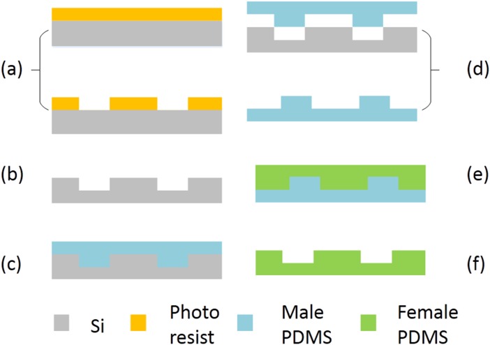
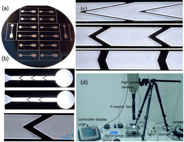
In this work, the experiment was carried out in a microfluidic channel made by polydimethylsiloxane (PDMS) using the lithography techniques (Figure 2):35 (a) the silicon is coated with photoresist (AZ 4620). After standard lithography (KarSuss MA6/BA6 photo-etching machine), the photoresist is developed to obtain a photoresist mask; (b) the silicon mould is obtained by ICP (Alcatel 601E ICP) dry etching process (Figures 3a, 3b, 3c); (c) the bi-component Sylgard 184 PDMS (Dow Corning Corporation, American) is injected on the silicon mould after mixed with ratio 10:1 and degasification, then heated at for 3 h 30 min to cure; (d) the solidified male PDMS mould is unveiled from the silicon mould; (e) the mixed PDMS is injected on the male PDMS mould, then heated at for another 3 h 30 min to cure; (f) the solidified female PDMS mould is unveiled from the male PDMS mould.
Figure 2.
Flowchart of the fabrication process.
Figure 3.
(a) The Si mold. (b) The upward, downward, and one enlarged obstacle of VOA with . (c) The VOA structures with . (d) The experimental setup used in this work.
The upward part and downward part with obstacle are cut from the female PDMS mould and two vents are drilled at both ends of upward part. After that, the upward part and downward part are treated with oxygen plasma (PVA TePla GIGA batch 310M plasma system) at 750 mTorr and 60 W for 22 s.36 Next, the upward part and downward part are lubricated together using deionized water with 3-aminopropyl triethoxysilane (APTES) solution and aligned manually below the optical extraordinarily large depth-of-field microscope (Keyenc VHX-1000). Finally, the chip is preserved in the oven at for 24 h in order to bond the two parts together.
Operation
The radius of spherical particle (Nano-Micro Technology Company, Suzhou, China) used for the experiment is , that C.V. . The concentration of particle solution is approximately , diluted using deionized water with Tween 80 and 14.5% (w/w) glucose. The particle solution is injected by digital syringe pump (RSP04-C, Jianshan Ruichuang Electronic Tec. Co., Ltd., China) and the particle movement in the channel is video captured at 4000 flames/s and shutter using a high speed camera (i-SPEED TR, Olympus Corporation, Japan) (Figure 3d). The pictures are exported by i-SPEED software suite. A series of pictures having the same particle in different time point are picked up and then the images are added together to obtain the trajectory of particle by MATLAB codes. In order to obtain the migration distance of the particles in channel, the software ImageJ is used to measure the center positions of particles. Experiments were repeated three times on each setup and at least 50 particles were measured for each experiment.
PARTICLE TRAJECTORY AND FLOW STREAMLINE
Code validation
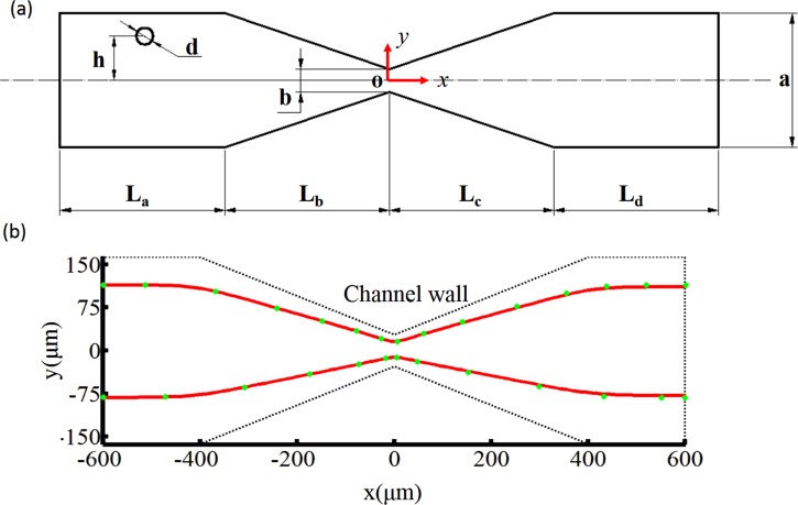
In order to verify the ALE simulation proposed in this work, we compared our numerical results with the published numerical results first. A particle movement benchmark through a converging-diverging microchannel is presented in Figure 4a.37 The agreement between our results and references shows the evidence of the presented computational procedures in this work (Figure 4b). Furthermore, we carry out three dimensional ALE simulations and corresponding experiments with the same input parameters. The parameters of the V-shaped obstacle array are as follows (Figure 1): , and (flow rate is ). Because the z co-ordinate of a particle center is not easy to be directly measured, two different z co-ordinates of the starting point for particle center (Dzi) near the channel wall are specified in the simulation that is and . Because the particle diameter used in this work is , the nearest distance from the surface of particle to the wall of channel is less than (about of Ho of channel) when . Under the simplification assumptions that the particles move with the fluid without any further external forces exert on the particles, nearly all particle trajectories having same start co-ordinate point on the x and y axes should be enveloped by the two particle trajectories with .
Figure 4.
(a) A schematic view of a circular particle in a converging-diverging microchannel. The geometrical parameters of the microchannel are: . (b) Particle trajectories in a converging-diverging microchannel. The solid lines represent the simulated trajectories using the ALE method presented in this work. The circles represent the numerical results obtained by Ai et al. in 2009.37
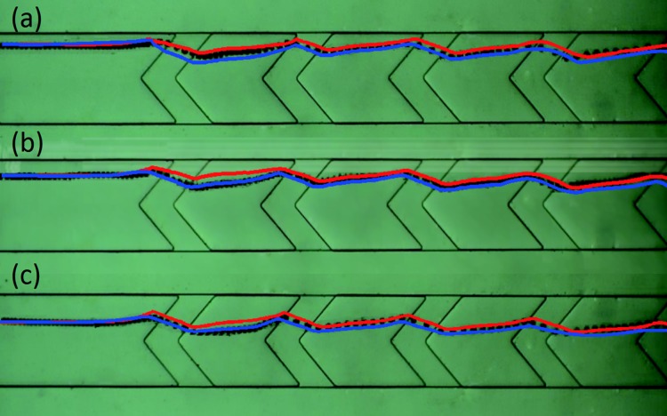
In experiments, five V-shaped obstacles are used, and the moving particles are recorded with the high speed camera. Three particle trajectories captured in the experiment, which have the y co-ordinates and , are used to verify the three dimensional ALE simulation results. We confirm the validity of simulation by checking if the trajectory of the experimental data is entirely enveloped by the numerically simulated trajectories in the xy plane. In Figure 5, the particle trajectory (black dotted line) is enveloped by the simulation results (red line denoting and the blue line denoting ). This means that the ALE simulation results are in agreement qualitatively with the corresponding experimental results.
Figure 5.
The comparison of simulation and experiment results. The black dotted line is the trajectory of the particle. The red and blue lines are the simulation results of and , respectively. (a) The comparison of particle for which . (b) The comparison of particle for which . (c) The comparison of particle for which .
Comparison between particle trajectory and flow streamline
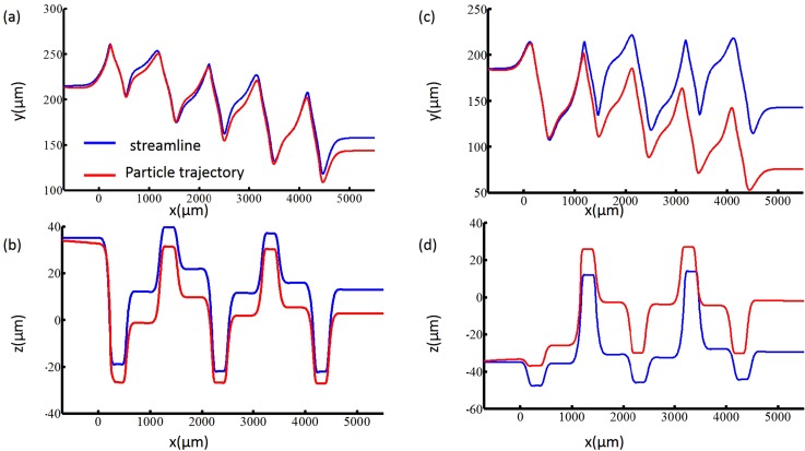
The particle movement information (or particle trajectory) in all three directions can be obtained using the ALE method. In the fluid field without particle, the streamline is a curve that is tangent to an instantaneous velocity field. The particle trajectory may be similar to the streamline if the size of particle is small compared to the dimensions of the channel and the density of particle is similar to the fluid density. When the size of particle is sufficiently large, the inertia and interaction between the particle and the channel wall causes particles to cross streamlines.27, 31 The initial co-ordinate value of particles in Table TABLE I. is used to compare the trajectory of the particle and the streamline for fluid velocity field without particles.38 Figure 6 shows that the particle trajectory and streamline move between the center line of channel and the channel wall in the y direction (Figures 6a, 6c), and simultaneously move up and down in the z direction (Figures 6b, 6d) when they move through the fluid channel in the x direction. The difference between the streamline and trajectory is obvious. The particle trajectory gradually focuses to the center of the channel in the vertical direction, while the streamline does not. In Figure 7, we compare the particle trajectories that the particles are initially arranged at the start points with the same value on the y direction but with the different values on the z direction. Because channel depth Ho is close to the diameter of particle (about 4/5 of channel depth of channel), the interactive effect between the channel wall and particles is strong when the particle moves off the center of channel in z direction. Therefore, the particles close to upper and under wall move close to center line of channel in z direction after passing several obstacles. At the same time, the focusing of the structure with VOA is the three-dimensional (3D) focusing, where particles are focused in both the horizontal and the vertical directions.
TABLE I.
The starting points analyzed for comparison of streamline and particle trajectory.
| Case1 | 215 | 35 |
| Case2 | 215 | −35 |
| Case3 | 185 | −35 |
| Case4 | 113 | 35 |
| Case5 | 113 | −35 |
| Case6 | 200 | 0 |
Figure 6.
Comparison between the streamline and particle trajectory, where (a) and (c) are x−y plane plots, and (b) and (d) are x−z plane plots. The starting co-ordinates of (a) and (b) are (case 1 in Table TABLE I.). The starting co-ordinates of (c) and (d) are (case 3 in Table TABLE I.). The geometrical parameters of VOA are: .
Figure 7.
Particle focusing effect along the channel depth direction via the particle trajectory simulation. The starting co-ordinates of (a) are (case 1 and case 2 in Table TABLE I.). The starting co-ordinates of (b) are (case 4 and case 5 in Table TABLE I.). The geometrical parameters of VOA are: .
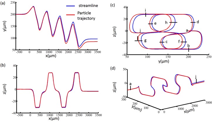
In Figure 8a, the streamline and particle trajectory start at , and end at for the streamline and for the trajectory. The deviation between particle trajectory and the streamline in the y direction is , about one quarter of particle diameter. In the z direction, however, the particle trajectory coincides with the streamline in the whole range, as shown in Figure 8b. This mean that the streamline in the vertical center of the channel can be used for prediction the particle trajectory in channel with VOA. Figure 9a shows the ALE simulation of lateral migration of particle trajectory with the angle of obstacle and . Compared with the large θ case, the obstacle with small θ results in a larger distance of lateral migration in the y direction, but also requires a larger displacement in the x direction to reach an equilibrium point. In order to evaluate the particle focusing performance, we propose an average lateral migration function LmU based on the particle trajectory as
| (10) |
where xbm and ybm are the x and y co-ordinates of the start of particle migration in the y direction; xem and yem are the x and y co-ordinates where particles reach equilibrium in the y direction; and are the lateral migration distance to the centre in the y direction and the distance in the x direction between point and , i.e., and .
Figure 8.
Comparison between the streamline and particle trajectory when the particles locate at the center of the channel of depth direction () and (case 6 in Table TABLE I.). (a) x−y plane plots. The following three pictures have the same legend. (b) x−z plane plots. (c) y−z plane plots. (d) Three dimensional plots of particle trajectories from the starting point a to the end point j. The geometrical parameters of VOA are: .
Figure 9.
(a) Trajectory of particle in x−y plane. Point a is the start point, and points b and c are the equilibrium positions. (b) Fy and v changes along the co-ordinate x. The values are normalized by their own maximum of absolute value. Here, .
OPTIMIZATION OF THE VOA DEVICE
Optimization objective
Even though the ALE method exhibits good accuracy to simulate the particle trajectories, the advantage is achieved at a high computational cost. For the particle trajectory shown in Figure 8, the computational time is nearly 2 days in a one node of a computer sever (each nodes with 2 CPUs 12Cores 2.67 GHz, 48G memory). Therefore, it is necessary to improve the computational efficiency for designing microfluidic devices. In Sec. 4, it is found that the streamline in the vertical center of the channel can be used for prediction the particle trajectory in channel with VOA. Here, four streamlines, which start at , and , are chosen to evaluate the performance of the average migration and the particle focusing. Furthermore, the LmU for each streamline is computed and the value is averaged, defined as LmUstr. Therefore, the function to depict the focusing performance based on the streamline is
| (11) |
where LmUi is the LmU for the ith streamline, and the is the weight for ith streamline integral, which is chosen as 0.25 in this work.
However, the streamline is obtained through a postprocessing computation based on the result of the fluid field. The computational cost is still quite expensive when the structure is complex. In this paper, a heuristic dimensionless design objective based on the Faxen's law with cheaper computational cost than the streamline is proposed to optimize the VOA devices. For the devices which manipulate the particle, the movement of particles in the y direction is affected by the y component of the fluid forces that acted on the surface of the particle. Figure 9b shows that, even though it does not response immediately as the stokes flow based on the Faxen law, the y component of the integral of fluid forces acted on the surface of particle changes in similar way as the changes of the y component of the fluid velocity. Because the movement of a particle in flow is mainly controlled by fluid forces that act on the surface of the particle, we heuristically use the value of the volume integral of v of the fluid domain to qualitatively approximate the focusing effect of a VOA chip. At the same time, the integral value is divided by the volume of unit channel with obstacle as
| (12) |
where are the mean velocity of flow at the inlet, the fluid domain, and volume of the fluid domain, respectively. It is known that the shape parameters of a VOA can influence the effect of particle focusing.39 The velocity component v can be adjusted by the geometric parameters of obstacle, for example, , etc., as shown in Figure 1.
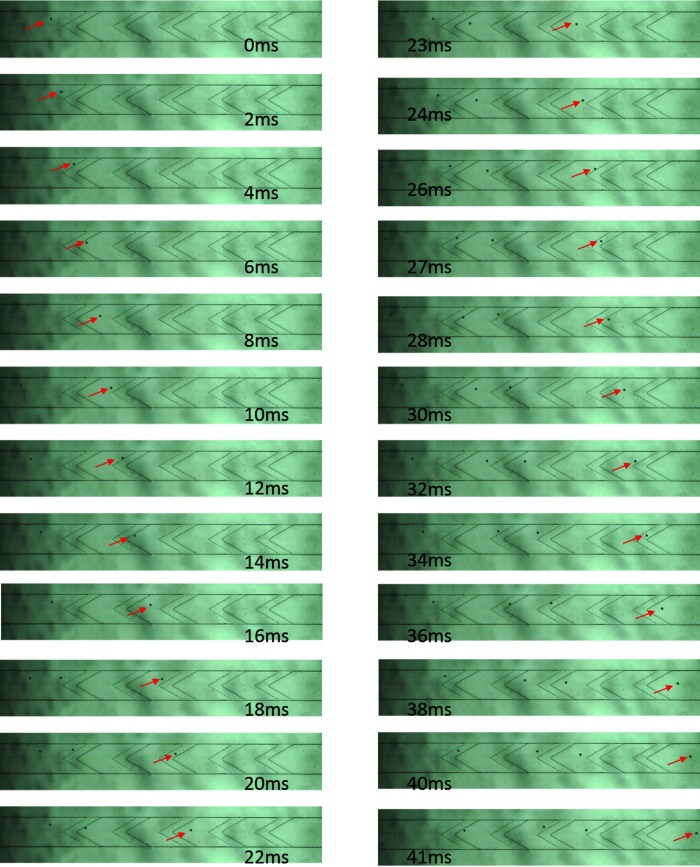
In order to calibrate the effect of the objective function in Eq. 12, we calculate the particle trajectories for the particles on and , and then evaluated the value of function LmU in Eq. 10 as . At the same time, the movement of particles is measured experimentally to validate the proposed dimensionless objective function (Figure 10). In the experiment, a series of angles () for VOA structure with are used, and the value of function LmU is evaluated as LmUex.
Figure 10.
The movement of particles in the channel with VOA. Geometry parameter of the obstacle is (enhanced online).
Parameter optimization
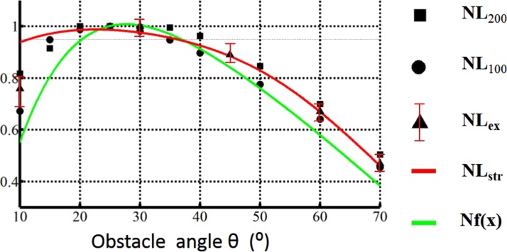
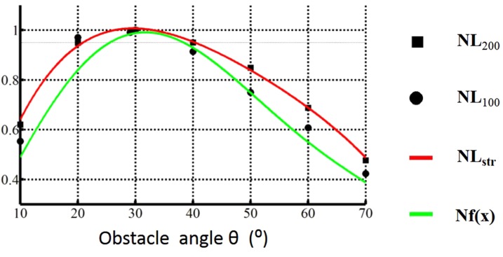
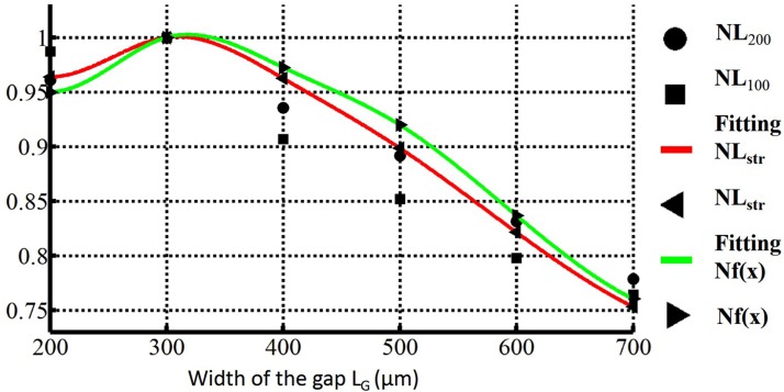
Based on the numerical experiments, we found that the value of function LmU is sensitive to the variation of θ or LG. This step is repeated for a series of angles as shown in Figures 1112. We would like to mention again that the computational time for each marked point of particle trajectory in Figures 1112 takes 2 days. At the same time, the value of is calculated for the same range of the angle variation. Because the calculation of the function is based on the integral of fluid domain without considering the existence of the particle, the computational cost is extremely low (CPU time: about 5 min for solving the fluid field) and computations can be evaluated for many points, using the parameter sweeping method. The comparison of the value of the functions LmU and for chip with and are shown in Figures 1112. Because the two aforementioned functions have different physical dimensions, the value of , and is normalized by the their maximum values and defined as , and Nf, respectively. Figure 11 shows that they match quite well for the angle variation in the range from to . The angle with the best performance, defined as , in particle focusing of is for the structure with . In the interval of for , that is , the value of , and varies less than 5%. This allows very loose tolerances for the designing and manufacturing of microfluidic devices. The simulation result in Figure 12 shows that the function in Eq. 12 is a good alternative objective to optimize the performance of particle focusing in VOA devices with reasonable cheap computational cost.
Figure 11.
Normalized average lateral migration and the normalized dimensionless object Nf. Geometry parameter of the obstacle is .
Figure 12.
Normalized average lateral migration and the normalized dimensionless object Nf. Geometry parameter of the obstacle is .
We further simulate the device with the value of LG from to . The angle θ is optimized for the objective function using the simplex method. Accordingly, the value of the function LmU for the optimized obstacles structure is calculated again using the ALE based particle trajectory. Figure 13 shows the comparison between the normalized value of , and Nf. The result shows that the value of and Nf coincides well within the interval of , while the optimal angle for the structure with is . As a result, using as an objective to optimize the geometric parameters of VOA type particle focusing microfluidic device is an effective and efficient choice.
Figure 13.
Normalized average lateral migration , the normalized dimensionless object Nf, and cubic interpretation fitting curve for .
CONCLUSION
Based on the experimentally verified particle trajectories using the arbitrary Lagrangian-Eulerian fluid-particle interaction method, this paper has analyzed the movement of particle in the V-shaped obstacle array type particle focusing microfluidic device. The characteristic of particles movement can be summarized as the following: (1) the particle trajectories show that the movement of particles is influenced by fluid-particle interaction effects strongly. (2) Particles are gradually approaching the centre of channel in depth and width of fluid channel; that is, the structure with VOA focusing is a three dimensional focusing method. (3) The equilibrium processes of particles are typically controlled by the detailed parameters of V-shaped obstacles. Instead of using the computational cost consuming ALE method, two objective functions are analyzed to evaluate the focusing effect of VOA device. The streamlines located in the vertical center of the channel can be used for prediction the particle trajectory in channel with VOA. Considering the complexity analysis of the streamline, another objective function based on the fluid velocity field without considering the existence of the particles, is proposed to effectively and efficiently optimize the key parameters of V-shaped obstacles. The optimization focusing devices is verified via the experiment and simulation.
ACKNOWLEDGMENTS
This work was supported by National Natural Science Foundation of China (Nos. 50975272 and 11034007) and the hundred talent project of the Chinese Academy of Sciences.
Poster, published as part of the 5th International Symposium on Microchemistry and Microsystems, Xiamen, China, May 2013.
References
- Xuan X. C., Zhu J. J., and Church C., Microfluid. Nanofluid. 9, 1 (2010). 10.1007/s10404-010-0602-7 [DOI] [Google Scholar]
- Ai Y., Joo S., Jiang Y., Xuan X., and Qian S., Biomicrofluidics 3, 022404 (2009). 10.1063/1.3122594 [DOI] [PMC free article] [PubMed] [Google Scholar]
- Ai Y., Beskok A., Gauthier D. T., Joo S. W., and Qian S., Biomicrofluidics 3, 44110 (2009). 10.1063/1.3267095 [DOI] [PMC free article] [PubMed] [Google Scholar]
- Ai Y., Qian S., Liu S., and Joo S. W., Biomicrofluidics 4, 13201 (2010). 10.1063/1.3279787 [DOI] [PMC free article] [PubMed] [Google Scholar]
- Patel S., Showers D., Vedantam P., Tzeng T.-R., Qian S., and Xuan X., Biomicrofluidics 6, 034102 (2013). 10.1007/s10404-012-1071-y [DOI] [PMC free article] [PubMed] [Google Scholar]
- Li M., Li S., Cao W., Li W., Wen W., and Alici G., Microfluid. Nanofluid. 14, 527 (2013). [Google Scholar]
- Liu T., Li C., Li H., Zeng S., Qin J., and Lin B., Electrophoresis 30, 4285 (2009). 10.1002/elps.200900289 [DOI] [PubMed] [Google Scholar]
- Song Y., Peng R., Wang J., Pan X., Sun Y., and Li D., Electrophoresis 34, 684 (2013). 10.1002/elps.201200416 [DOI] [PubMed] [Google Scholar]
- Jen C. P., A. Maslov N., Shih H. Y., Lee Y. C., and Hsiao F. B., Microsyst. Technol. 18, 1879 (2012). 10.1007/s00542-012-1498-9 [DOI] [Google Scholar]
- Liao S., Cheng I., and Chang H., Microfluid. Nanofluid. 12, 201 (2012). 10.1007/s10404-011-0863-9 [DOI] [Google Scholar]
- Lu Q., Terray A., Collins G. E., and Hart S. J., Lab Chip 12, 1128 (2012). 10.1039/c2lc21017g [DOI] [PubMed] [Google Scholar]
- Ng A. H. C., Choi K., Luoma R. P., Robinson J. M., and Wheeler A. R., Anal. Chem. 84, 8805 (2012). 10.1021/ac3020627 [DOI] [PubMed] [Google Scholar]
- Ramadan Q. and Gijs M. A. M., Microfluid. Nanofluid. 13, 529 (2012). 10.1007/s10404-012-1041-4 [DOI] [Google Scholar]
- Choi S., Song S., Choi C., and Park J.-K., Lab Chip 7, 1532 (2007). 10.1039/b705203k [DOI] [PubMed] [Google Scholar]
- Choi S., Song S., Choi C., and Park J.-K., Small 4, 634 (2008). 10.1002/smll.200700308 [DOI] [PubMed] [Google Scholar]
- Choi S. and Park J.-K., Anal. Chem. 80, 3035 (2008). 10.1021/ac8001319 [DOI] [PubMed] [Google Scholar]
- Choi S., Song S., Choi C., and Park J.-K., Anal. Chem. 81, 1964 (2009). 10.1021/ac8024575 [DOI] [PubMed] [Google Scholar]
- Lee M. G., Choi S., Kim H. J., Lim H. K., Kim J. H., Huh N., and Park J.-K., Appl. Phys. Lett. 98, 253702 (2011). 10.1063/1.3601745 [DOI] [Google Scholar]
- Lee M. G., Choi S., and Park J.-K., J. Chromatogr. A 1218, 4138 (2011). 10.1016/j.chroma.2010.11.081 [DOI] [PubMed] [Google Scholar]
- Masaeli M., Sollier E., Amini H., Mao W., Camacho K., Doshi N., Mitragotri S., Alexeev A., and Di Carlo D., Phys. Rev. X 2, 031017 (2012). 10.1103/PhysRevX.2.031017 [DOI] [Google Scholar]
- Zhou J. and Papautsky I., Lab Chip 13, 1121 (2013). 10.1039/c2lc41248a [DOI] [PubMed] [Google Scholar]
- Yang R., Hou H. H., Wang Y. N., Lin C., and Fu L., Biomicrofluidics 6, 034110 (2012). 10.1063/1.4739073 [DOI] [PMC free article] [PubMed] [Google Scholar]
- Seo K. W., Choi Y. S., and Lee S. J., Exp. Fluids 53, 1867 (2012). 10.1007/s00348-012-1403-4 [DOI] [Google Scholar]
- Martel J. M. and Toner M., Phys. Fluids 24, 32001 (2012). 10.1063/1.3681228 [DOI] [PMC free article] [PubMed] [Google Scholar]
- Aoki R., Yamada M., Yasuda M., and Seki M., Microfluid. Nanofluid. 6, 571 (2009). 10.1007/s10404-008-0334-0 [DOI] [Google Scholar]
- Sugaya S., Yamada M., and Seki M., Biomicrofluidics 5, 24103 (2011). 10.1063/1.3580757 [DOI] [PMC free article] [PubMed] [Google Scholar]
- Di Carlo D., Lab Chip 9, 3038 (2009). 10.1039/b912547g [DOI] [PubMed] [Google Scholar]
- Worner M., Microfluid. Nanofluid. 12, 841 (2012). 10.1007/s10404-012-0940-8 [DOI] [Google Scholar]
- Forbes T. and Kralj J., Lab Chip 12, 2634 (2012). 10.1039/c2lc40356k [DOI] [PubMed] [Google Scholar]
- Liu Z. and Korvink J. G., Eng. Optim. 40, 529 (2008). 10.1080/03052150801985544 [DOI] [Google Scholar]
- Hau W. L. W., Liu Z., Korvink J. G., Zengerle R., and Ducree J., in IEEE 21st International Conference on Micro Electro Mechanical Systems, 2008 (IEEE, 2008), pp. 633–636.
- Hu H. H., Int. J. Multiphase Flow 22, 335 (1996). 10.1016/0301-9322(95)00068-2 [DOI] [Google Scholar]
- Masud A. and Hughes T. J. R., Comput. Methods Appl. Mech. Eng. 146, 91 (1997). 10.1016/S0045-7825(96)01222-4 [DOI] [Google Scholar]
- See www.comsol.com for the user's guide to COMSOL Multiphysics.
- Liu Y., Deng Y., Zhang P., Liu Z., and Wu Y., J. Micromech. Microeng. 23, 075002 (2013). 10.1088/0960-1317/23/7/075002 [DOI] [Google Scholar]
- Bhattacharya S., Datta A., Berg J. M., and Gangopadhyay S., J. Microelectromech. Syst. 14, 590 (2005). 10.1109/JMEMS.2005.844746 [DOI] [Google Scholar]
- Ai Y., Joo S. W., Jiang Y., Xuan X., and Qian S., Electrophoresis 30, 2499 (2009). 10.1002/elps.200800792 [DOI] [PubMed] [Google Scholar]
- See supplementary material at http://dx.doi.org/10.1063/1.4821170 for simulation result for velocity field, and some other comparisons of trajectories and streamlines.
- Kim K., Seo H.-K., and Kim Y.-J., “Sheathless microfluidic particle focusing technique using slanted microstructure array,” Microfluid. Nanofluid. (published online). 10.1007/s10404-013-1230-9 [DOI]


