Abstract
In recent years, conjugated polymers have attracted considerable attention from the imaging community as a new class of contrast agent due to their intriguing structural, chemical, and optical properties. Their size and emission wavelength tunability, brightness, photostability, and low toxicity have been demonstrated in a wide range of in vitro sensing and cellular imaging applications, and have just begun to show impact in in vivo settings. In this Perspective, we summarize recent advances in engineering conjugated polymers as imaging contrast agents, their emerging applications in molecular imaging (referred to as in vivo uses in this paper), as well as our perspectives on future research.
1. Introduction
By directly visualizing cellular functions and molecular processes non-invasively, molecular imaging has the potential to transform disease diagnosis, stratify therapy, and aid in drug discovery and validation.1–3 Among various in vivo imaging modalities, optical imaging offers unique advantages such as high sensitivity and resolution, multiplexing capability, low cost, and versatility in both in vitro and in vivo applications.4 Typically, optics-based molecular imaging conjugates a targeting ligand (e.g., antibodies, peptides, aptamers, and small-molecule antagonists) with fluorescent dye molecules to interrogate a particular disease biomarker or pathway in lab animals and potentially human beings. However, conventional organic dye molecules are neither bright nor photostable particularly in the near infrared (NIR) spectrum, considered to be a ‘clear window’ for in vivo imaging due to improved light penetration depth and reduced tissue autofluorescence background.5
To go beyond the intrinsic limitations of small-molecule dyes, a variety of new exogenous imaging probes have been developed recently. The most prominent includes semiconductor quantum dots (QDs) and conjugated polymers (CPs).6–9 Compared to small-molecule organic dyes, QDs are superior in many spectrum aspects, such as brightness, photostability, emission color tunability, Stokes shift, and absorption and emission profiles. At this time, however, high-quality quantum dots are mainly made with toxic chemical elements and thus their long-term in vivo toxicity is a major concern.10, 11 Their potential toxicity prevents them from clinical translation especially as a screening tool where periodic injections are expected. In this regard, CPs with high brightness, resistance against photobleaching, and benign biochemical properties have become a highly promising alternative for high-sensitivity and high-specificity imaging with translational potential.
CPs are macromolecules with π-conjugated backbones. Due to their unique electric conductivity and photoluminescence, they have proven useful in a number of research fields, such as sensors, light emitting devices, imaging probes, as well as drug delivery vehicles.12–22 Common CPs include polyfluorene (PF), poly(fluorenyldivinylene) (PFV), poly(phenylene ethynylene) (PPE), poly(p-phenylenevinylene) (PPV) and derivatives. These CPs, however, cannot be directly used for biomedical applications due to their poor solubility in water.
A natural solution is to add pendant groups onto the polymer backbone, thus converting CPs into conjugated polyelectrolytes (CPEs).23, 24 Alternatively, CPs can be made into nanoparticles stabilized with amphiphilic surfactants or block copolymers.25, 26 Indeed, a majority of the in vivo applications of CPs reported so far are designed around CP nanoparticles, due to the flexibility in CP selection, simple synthetic protocols, excellent size range for tissue penetration and plasma circulation, high photostability, inert biochemical behaviors, and easiness of doping or mixing CPs. Because detailed reviews of CP chemical synthesis and applications in cellular imaging can be found elsewhere,9, 27–29 we will only feature the recent advances in molecular imaging using CPs, which serves as the bases for our opinion on future research directions.
2. Sentinel lymph node mapping
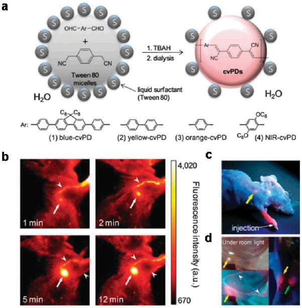
One of the first in vivo applications of CPs was reported by Kwon and coworkers for sentinel lymph node (SLN) imaging.30 SLN is the first group of lymph nodes receiving metastatic cancer cells by direct lymphatic drainage from a primary tumor. Improved identification and imaging of SLNs over the conventional blue dye-based visual detection is thus of clinical significance for cancer staging and surgery. To help address this problem, Kwon et al synthesized cyanovinylene-backboned polymer dots (cvPDs) via in situ colloidal polymerization. The fluorescence emission of the synthesized dots can be readily tuned throughout the visible and near infrared (NIR) spectrum using different monomers (Fig. 1a). For example, the NIR-cvPDs exhibit broadband absorption and red-to-NIR emission peaking at 693 nm. In contrast to majority of chromophores that exhibit serious aggregation-induced quenching, the CP dots shown here still maintain a quantum efficiency of 21%. Remarkably, the NIR-cvPDs are so bright that when injected into a mouse paw, not only the axillary lymph nodes but also the lymphatic vessels can be visualized by the naked eye (Fig. 1b–d).
Figure 1.
cvPDs nanoparticles for sentinel lymph node imaging. (a) Schematic diagram depicting colloidal synthesis of cvPDs of various emission wavelengths. (b) Pseudo-color NIR fluorescence images of a mouse injected intradermally with NIR-cvPDs into the right paw. Arrows and arrowheads indicate axillary lymph node and lymphatic vessels, respectively. (c&d) True-color fluorescence photographs of a cvPD-injected mouse taken by a UV handheld lamp. Two SLNs, axillary and lateral thoracic nodes, and lymphatic vessels are indicated by yellow, green arrows and arrowheads, respectively. (Chem. Comm. 46, 1617–1619, 2010)
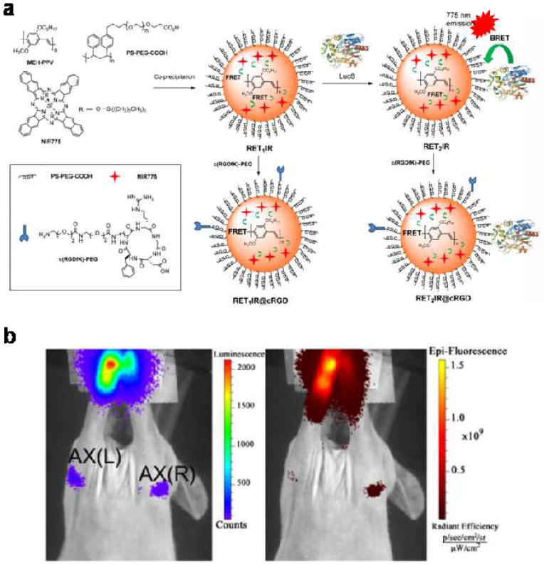
Similar SLN mapping experiments have also been reported by Rao et al. Instead of using the classic fluorescence mode for imaging, they designed an assay integrating bioluminescence resonance energy transfer (BRET) and fluorescence resonance energy transfer (FRET) (Fig. 2a).31 The BRET process bypasses the strong autofluorescence background (and consequently poor signal-to-noise ratio) encountered by fluorescence imaging, whereas the FRET assay is utilized to shift the emission to the NIR region, again for reduced background. To realize this smart dual resonance energy transfer relay process, a CP poly[2-methoxy-5-((2-ethylhexyl)oxy)-p-phenylenevinylene] (MEH-PPV) and a NIR dye fluorescing at 775 nm maximum are coprecipitated into nanoparticles stabilized with an amphiphilic polymer, polystyrene graft ethylene oxide with terminal carboxyl groups (PS-PEG-COOH). Luc8 (an eight-mutation variant of R. reniformis luciferase) emitting blue light peaking at 480 nm is used as the BRET energy donor and is linked to the nanoparticle surface at an average density of 5.3 molecules per nanoparticle.
Figure 2.
BRET-FRET-NIR nanoparticles for SLN imaging. (a) Schematic of self-luminescing BRET-FRET-NIR nanoparticles, in which energy from chemiluminescence is transferred to the CP matrix through BRET, and relayed to the NIR dye through FRET. (b) Bioluminescence and fluorescence imaging of lymphatic basins in a mouse 10 mins post injection of the nanoparticles intradermally in the forepaws. (Nat. Comm. 3, 2012).
Upon adding Luc8’s substrate, coelenterazine, the chemiluminescence energy is first transferred to the nanoparticle polymer matrix, PEH-PPV, and then relayed to the doped dye for detection in the NIR region. When administered in vivo, both bioluminescence signals and NIR fluorescence can be detected (Fig. 2b). However, detection based on bioluminescence appears to be much more sensitive than NIR fluorescence imaging for both lymph node and tumor targets. This is perhaps not too surprising, because the BRET-FRET assay needs further optimization to improve energy transfer efficiency. In particular, increasing the number of Luc8 molecules per nanoparticle and reducing the size of the MEH-PPV nanoparticle should dramatically improve the BRET efficiency, since energy transfer is extremely sensitive to the distance between energy donor and acceptor.
Overall, imaging of sentinel lymph nodes represents one of the best opportunities for clinical translation of CP-based nanoprobes especially for breast cancer and skin melanoma because locations of nearby nodes can be relatively superficial, ideal for optical imaging and related imaging modes (e.g., photoacoustic (PA) imaging).
3. In vivo tumor imaging
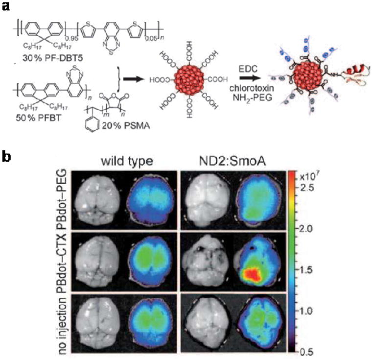
Besides imaging the lymphatic system, non-invasive imaging of tumors is another emerging application for CPs. A common theme of published reports is to use FRET to shift fluorescence emission to the NIR for improved tissue penetration depth and reduced autofluorescence background by packaging CP-based energy donors and various energy acceptors into nanoparticles. For example, Chiu et al made highly bright polymer-blend dots (PBdots) by blending a visible-light-harvesting polymer (energy donor) and another deep-red emitting CP (energy acceptor) (Fig. 3a).32 Due to the large absorptivity, the PBdots are remarkably 15 times brighter than color-matching quantum dots, which are already approximately 20 times brighter than small-molecule organic dyes. Certainly, the sizes of PBdots (15 nm) and quantum dots (6 nm) are significantly bigger than those of small-molecule dyes (1–2 nm).
Figure 3.
CTX targeted PBdots for brain tumor imaging. (a) Schematic of PBdot functionalization and CTX conjugation. (b) Fluorescence imaging of healthy brains in wild-type mice (left) and medulloblastoma tumors in ND2:SmoA1 mice (right). Each mouse was injected through the tail vein with 50μL of a 1μM solution of either the non-targeted PBdot-PEG (top), or CTX-targeted PBdots (middle). As a control, some mice did not receive an injection (bottom). (Angew. Chem. 50, 3430–3434, 2011)
The key to the bright deep red emission of the PBdots is to package the energy acceptor in the polymer FRET pair into nanoparticles at very high concentration (30%) while maintaining a high fluorescence quantum yield (56%), which is significantly higher than that of alternating polymers with the energy donor and acceptor units polymerized into the same backbone.33 To deliver the nanoprobe to brain tumors, one of the least accessible tumor targets due to the blood-brain barrier, PBdots were functionalized with a peptide, chlorotoxin (CTX). In a transgenic mouse model resembling human medulloblastoma, the most common malignant childhood brain tumor, specific delivery and ex vivo imaging were compared to control groups, including wild type mice as well as non-targeted PBdots (Fig. 3b).
Similar to blending two CPs discussed above, improving energy transfer efficiency by encapsulation of other CP-based FRET pairs has been the focus of several recent in vivo imaging applications, where FRET Stokes shifted fluorescence emission to the NIR region. In one example, far-red/NIR emitting nanoparticles coencapsulated CP energy donor poly[9,9-bis(2-(2-(2-methoxyethoxy)ethoxy)ethyl)fluorenyldivinylene] (PFV) with a fluorophore energy acceptor 2-(2,6-bis((E)-4-(phenyl(43-(1,2,2-triphenylvinyl)-[1,13-biphenyl]-4-yl)amino)styryl)-4H-pyran-4-ylidene)malononitrile (TPE-TPA-DCM). This created a biocompatible bovine serum albumin (BSA) nanoparticles (Fig. 4a) with aggregation-induced emission (AIE) characteristics.34 Fluorescence emission from the nanoparticles was optimized by fixing the concentration of TPE-TPA-DCM in BSA while varying that of PVF.
Figure 4.
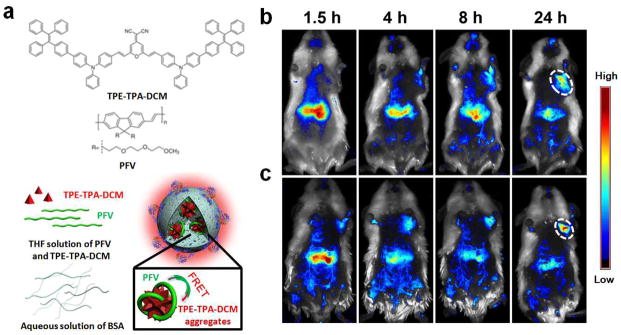
TPE-TPA-DCM and PFV doped BSA nanoparticles for non-invasive tumor imaging. (a) Chemical structures of TPE-TPA-DCM and PFV as well as schematic illustration of the PFV/TPE-TPA-DCM co-loaded BSA nanoparticles. In vivo non-invasive fluorescence imaging of H22-tumor-bearing mice after intravenous injection of PFV/TPE-TPA-DCM co- loaded non-targeted BSA nanoparticles (b), and PFV/TPE-TPA-DCM co-loaded RGD-targeted BSA nanoparticles (c). The white circles indicate the tumor sites. (Advanced Healthcare Materials 2, 500–507, 2013)
As the concentration of the energy donor increases, so does the nanoparticle absorptivity and fluorescence emission intensity. The final molar ratio of PFV (based on repeat unit) to TPE-TPA-DCM is fixed at 18.8:1 for cellular and in vivo molecular imaging experiments. The use of AIE fluorogen as the energy acceptor has the advantage that it eliminates fluorescence quenching of the acceptor in the aggregates, which improves the FRET signal output. BSA molecules on the surface of the nanoparticles feature a variety of reactive sites for bioconjugation. When the nanoparticles are functionalized with integrin-targeting RGD peptides and injected into a murine hepatic H22 tumor model, they localize in tumor sites with approximately 2-fold increase in fluorescence intensity over their non-targeted counterpart throughout the post-injection period up to 24 hours (Fig. 4b&c). At the same time, major uptake by liver was also observed for both targeted and non-targeted nanoparticles.
In addition to using different energy donors and acceptors to form FRET pairs in nanoparticles, most recently, Liu’s group developed another approach to encapsulate CPs with intramolecular energy transfer characteristics into nanoparticles. As mentioned above, copolymerization of energy donor and acceptor units into the same backbone for intramolecular energy transfer often reduces fluorescence quantum efficiency.32 Instead of arranging the two monomers into alternating or random polymers, they synthesized a highly emissive conjugated block copolymer, poly[(9,9-dihexylfluorene)-co-2,1,3-benzothiadiazole-co-4,7-di(thiophen-2-yl)-2,1,3-benzothiadiazole] (PFBTDBT10), which contain 90% of the donor units and 10% of the acceptor units in the polymer backbone. The low acceptor content in the polymer backbone is sufficient to realize complete energy transfer and minimize fluorescence quenching when the polymer collapses into nanoparticles (Fig. 5a).35 The resulting nanoparticles have an impressive fluorescence quantum yield of 27% in the far red/NIR spectrum and a large Stokes shift of 233 nm in aqueous buffer. Using the same H22 murine hepatic tumor model described earlier (except using folic acid as the targeting ligand), similar tumor targeting and imaging efficiency has also been achieved (Fig. 5b).
Figure 5.
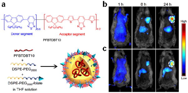
Nanoparticles loaded with PFBTDBT10 block copolymers for tumor molecular targeting and imaging. (a) Chemical structures of PFBTDBT10 as well as the schematic illustration of PFBTDBT10-loaded folic acid-targeted nanoparticles. Two narrow-bandgap monomers, 2,1,3-benzothiadiazole (BT) and 4,7-di(thiophen-2-yl)-2,1,3-benzothiadiazole (DBT), are incorporated into the conjugated backbone of poly(9,9-dihexylfluorene) to yield PFBTDBT10. The concentration of DBT in the energy acceptor unit is set at 10 mol% of the total monomers to ensure complete energy transfer while avoiding self-quenching. (b) In vivo non-invasive fluorescence images of H22 tumor-bearing mice at various time points post intravenous injection of the targeted nanoparticles and non-targeted nanoparticles. The white circles indicate the tumor sites. (Small doi: 10.1002/smll.201300171. Epub ahead of print)
4. Perspectives
As a relatively new imaging modality, optical imaging of molecular events and pathways represents an exciting opportunity for in-depth understanding of normal physiology, disease pathology, advanced diagnostics, as well as new drug screening and validation. Compared to other imaging modalities, optical imaging is nearly unique as it can readily transit between zoomed-out imaging on the systems’ level to zoomed-in imaging on the cellular and molecular level. In this process, novel imaging probes transcending the intrinsic limitation of conventional small-molecule organic fluorophores are of particular interest. As discussed above, CPs have emerged as a promising new class of imaging probes due to their superior electronic and optical properties, such as high extinction coefficients and efficient intra-/intermolecular exciton migration. In the future, we predict widespread use of these agents with potential clinical translation. In particular, we envision four research directions that may be of particular interest in the next few years. They are deep tissue imaging, multimodality imaging, molecular theranostics, and biocompatible and renal clearable CP nanoprobe engineering.
4.1. Deep tissue imaging
As shown above, virtually all current uses of CPs in fluorescence in vivo imaging are for superficial targets (subcutaneous lymph nodes and tumors). This is understandable because even in the NIR spectral region, light penetration is largely limited to the millimeter range. One approach to mitigate this problem is to engineer CPs with strong NIR absorption and emission because fluorescence uses light that must travel both in and out of tissues. However, the limited light penetration depth due to strong photon absorption and scattering by biological tissues is an inherent issue for optical imaging and cannot be completely eliminated.
An alternative method to improve imaging depth is photoacoustics, utilizing heat (non-irradiative) dissipated by PA contrast agents, because even for a fluorophore with high fluorescence quantum yield, a substantial percentage of energy from the absorbed excitation photon is released in the form of heat. In addition, materials design and chemistry provides additional opportunities to fine tune both radiative and non-radiative decay within a molecule.36 PA imaging combines optical interrogation of a target by pulsed laser irradiation with ultrasound detection of the resulting thermally-induced acoustic waves (light travels one way and sound travels one way). The integration of high optical contrast enhanced by the specific optical absorption of contrast agents with the spatial resolution of ultrasound detection deep within tissue has made PA imaging a promising tool for molecular imaging. Currently, most exogenous contrast agents for PA imaging are based on inorganic nanoparticles and small-molecule NIR dyes. We believe some CPs can offer unique advantages for this relatively new imaging mode because of their large absorptivity and outstanding photostability, unusual features for organic materials that have been repeatedly reported but largely underutilized so far. These properties are critically important for PA imaging, and can become a highly active research direction.
To illustrate the concept of PA imaging using CPs, we recently synthesized a NIR-absorbing CP, poly[9,9-bis(4-(2-ethylhexyl) phenyl) fluorene-alt-co-6,7-bis(4-(hexyloxy)phenyl)-4,9-di(thiophen-2-yl) thiadiazoloquinoxaline] (PFTTQ) (Fig. 6a), and encapsulated it into nanoparticles using a standard emulsion process.37 Transmission electron microscopy (TEM) and UV absorption measurements of the as-synthesized nanoparticles show a mean diameter of 70 nm, and a broad and strong absorption peak from 700 to 900 nm (note that possible absorption beyond 900 nm is not detected due to limited UV detector spectral range) (Fig. 6b). Compared to the most common PA imaging contrast agent, gold nanorods (AuNRs) with absorption at the longitudinal surface plasmon peak (overall sizes are also similar), PFTTQ’s absorptivity at 800 nm is approximately a quarter of that of AuNRs of the same weight.
Figure 6.
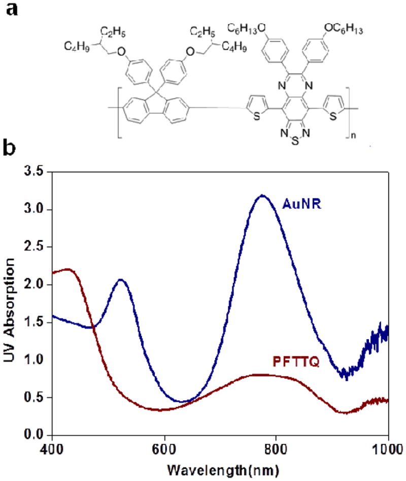
CP as a new PA imaging contrast agent. (a) Chemical structure of PFTTQ. (b) UV absorption measurements of AuNRs and PFTTQ nanoparticles of the same weight concentration.
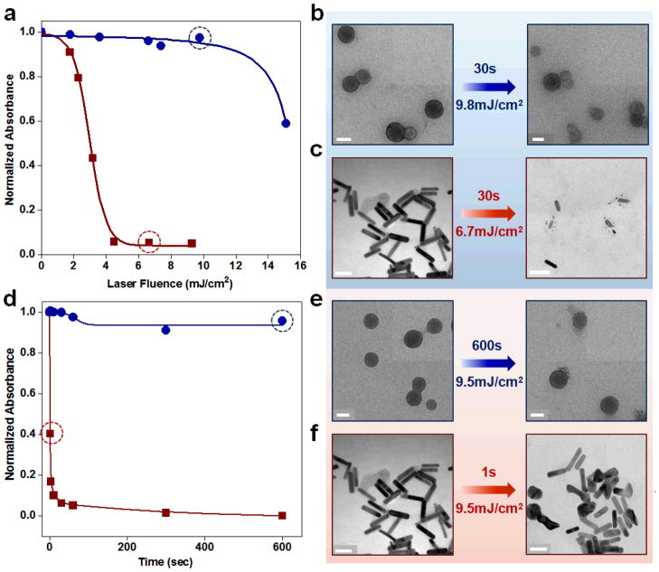
This is impressive for an organic material considering AuNRs offer orders of magnitude higher molar extinction efficiency over dyes and quantum dots, and the highest absorptivity per unit volume compared to other gold nanostructures (such as spherical particles and nanoshells). More remarkably, the PFTTQ nanoparticles are significantly more stable against photo-induced degradation compared to AuNRs, the most popular PA imaging contrast agent. As shown in Figure 7a, when PFTTQ nanoparticles and AuNRs are treated by a pulsed laser for 30 seconds with increasing pulse fluence from 2 to 15 mJ/cm2 (fixed time, varying laser intensity), AuNRs quickly degrade and lose their characteristic NIR absorption profile; whereas PFTTQ nanoparticles remain intact for laser fluences up to ~10 mJ/cm2. TEM imaging before and after laser irradiation shows that the PFTTQ nanoparticles are largely intact, but the AuNRs are shortened and fragmented (Fig. 7b&c). Similarly, under the same laser irradiation (fixed laser fluence at 9.5 mJ/cm2, varying exposure time), AuNRs are degraded in less than a second, but the CP nanoparticles are stable even after 10-minute exposure (Fig. 7d–f). PA imaging of PFTTQ nanoparticle and AuNR suspensions show similar results as the UV absorption measurements (data not shown). The PA signal from AuNRs quickly drops when illuminated with a pulsed laser of high pulse fluence or for extended periods.
Figure 7.
Photostability comparison of PFTTQ nanoparticles and AuNRs. PFTTQ nanoparticles and AuNRs are irradiated by a pulsed laser for 30 seconds with increasing laser pulse fluence from 2 to 15 mJ/cm2. UV absorption measurements (a), and TEM imaging of PFTTQ (b) and AuNRs (c) before and after laser irradiation both show superior photostability of the CP. A significant amount of AuNRs are found fragmented and shortened. PFTTQ nanoparticles and AuNRs are also irradiated with the same laser pulse fluence (9.5 mJ/cm2) for varying durations (1 to 600s). UV absorption measurements (d) and TEM imaging (e&f) of nanoparticles before and after laser irradiation again show improved stability for PFTTQ over AuNRs (many fused together). All scale bars are 50 nm.
The improved photostability of CP nanoparticles over AuNRs is perhaps a little surprising because inorganic nanomaterials are generally perceived to be more stable contrast agents against laser irradiation than organic compounds. A closer look at the two types of nanoparticles indicates that the photostability of CPs are highly dependent upon their molecular structures as well as the encapsulation matrix and packaging.38, 39 Fortunately, due to the fast advances in organic electronics, critical parameters influencing the stability of CPs have been mapped out, which can be used as a guideline for PA contrast agent synthesis. In contrast, AuNRs can melt into spherical particles of similar volumes or even fragment into smaller particles under pulsed laser irradiation.40, 41
High-resolution TEM shows that, different from thermal melting which starts from the nanomaterial surface, the photothermal melting process starts with the formation of defects inside AuNRs.42 Enhanced photostability makes CP nanoparticles a very promising probe for bioimaging utilizing high-fluence or extended laser illumination, such as PA imaging and multiphoton microscopy, and enables the possibility for tracking complex biomolecular events in real-time.
4.2. Multimodality imaging
The second research direction is to integrate CP-based optical imaging with other imaging modalities for specific and sensitive detection of multiple diseases, since each type of nanoprobe displays distinct advantages as well as limitations. For example, gadolinium (Gd) chelates and magnetic nanoparticles are extensively used in magnetic resonance imaging (MRI) because MRI offers high-resolution and excellent tissue penetration depth. On the other hand, MRI is not as sensitive as optical imaging or positron emission tomography, and is difficult to visualize in microscopic tissue examination. Similarly, CP nanoparticles feature high sensitivity and resolution, multiplexing capability and real-time detection, and quantitative analysis, but, as aforementioned, the tissue penetration depth of optical imaging is limited.
In this context, engineering nanocomposites with complementary functionalities can synergistically combine the strengths of individual modalities. For this application, CPs are quite unique in that they can be doped with other functional contrast agents into a nanoparticle, aggregated into a polymer matrix to encapsulate other contrast agents, or used as individual macromolecular structure scaffolds to immobilize other functional parts, providing flexibility in nanoprobe design. Liu’s group recently demonstrated a couple of examples by co-doping CPs and iron oxide nanoparticles into PLGA nanoparticles and by immobilizing Gd3+ onto chelator-modified hyperbranched CPs to create fluorescent and magnetic dual modality nanoprobes.43, 44 By combining different functionalities intelligently, new imaging modes unavailable from the original constituents may be created as well. For example, combination of NIR-absorbing compounds with magnetic nanoparticles enables magnetic motive PA imaging, which is capable of improving PA imaging contrast by 2–3 orders of magnitude.45
4.3. Molecular theranostics
The third direction of major significance is towards theranostics, where imaging and therapy are combined into a single system in which imaging can be used to identify the disease target and also monitor the progression of therapy. Due to their diverse molecular structures and side-chain modifications, CPs can be used as nanocarriers for both small-molecule drugs and biologics,26 and potentially with on-demand drug release profile upon laser stimulation. Alternatively, CPs themselves can also provide therapeutic functions via multiple mechanisms. Under light irradiation, excited CPs could generate heat or reactive oxygen species (ROS) to directly damage cancer and bacterial cells, or to potentiate other drug actions.15, 46, 47 Further development of CP nanoparticles with integrated diagnostic power, treatment, and feedback information represents a major step towards molecular theranostics and personalized medicine.
4.4. CP in vivo compatibility and clearance
The fourth area that deserves intense study is toxicity and in vivo clearance of CP contrast agents. As discussed above, in vivo molecular imaging using CPs is an emerging field, and has the potential for clinical translation. Encouragingly, for the small number of papers published so far, virtually all formulations show low or no toxicity in cells and living animals. This is not too surprising because CPs are hydrophobic and bioinert, thus do not cause acute cytotoxicity and systemic toxicity.
Under in vivo conditions, systemically administered CP nanoprobes mainly accumulate in the mononuclear phagocyte system (MPS), such as liver and spleen. For potential clinical translation, a key question to ask is the long-term toxicity and in vivo clearance, which are largely unknown at this time. Prolonged tissue retention is of particularly concern if CPs are used as a diagnostic and screening tool, where systemic administration may be performed periodically. In general, the US Food and Drug Administration requires that agents injected into the human body, especially diagnostic agents, be cleared completely in a reasonable time to minimize body exposure to the agent and the chance that the agent will interfere with other diagnostic tests.48 Thus, after imaging, quick and complete clearance of nanoparticle contrast agents is highly desirable.
Several excretion pathways are possible. For example, the hepatobiliary system such as the liver efficiently traps nanoparticles that do not undergo renal clearance, because one of liver’s intrinsic physiological functions is to eliminate foreign nanoparticles and viruses. Interestingly, even for very long nanostructures such as single-wall carbon nanotubes, as long as the cross-section is small, they can be slowly cleared out of the body via the biliary pathway (secreted into feces).49 The advantages of CP hepatic clearance include (1) quick and efficient capture of intravascular CP nanoparticles by the liver, and (2) many CPs are bioenert, making them not easily broken down by the liver, thus relieving the difficulty to evaluate clearance for complex CP catabolites. On the other hand, despite quick liver uptake, hepatic processing and biliary excretion are very slow, resulting in prolonged retention within the liver.50 In this regard, renal clearance represents the most desirable approach to addressing the long-term toxicity issue and complete in vivo clearance.
It is well-established that particle renal filtration is highly dependent on particle size. Particles smaller than 6 nm in hydrodynamic diameter are quickly filtered out by the kidney, and particles greater than 8 nm are not; whereas filtration of particles within the intermediate range depends on surface charge.50, 51 For in vivo targeting and imaging applications, however, rapid renal clearance of ultra-small nanoparticles (< 6nm) is often not desired because localization of imaging probes into targeted tissues requires extended plasma circulation time. In addition, even though CP nanoparticles are made ultra-small initially, modification of their surface with non-fouling materials (e.g., polyethylene glycol) to minimize non-specific binding and targeting ligands based on macrobiomolecules (e.g., antibodies, aptamers, and peptides) to enhance specific uptake will significantly increase the overall size beyond the filtration cutoff threshold.
In light of these conflicting design parameters where long circulating probes are favored for binding with target tissues but rapid renal clearance is ideal to minimize toxicity risks, clever probe design strategies are needed. In this regard, CPs are highly qualified to achieve this goal because both individual CP molecules and CP nanoparticles possess highly modifiable chemistry, thanks to decades of research on polymer science, bioconjugation chemistry, and nano-interface. For example, individual CP molecules smaller than 6 nm may be linked to a targeting biomolecule through cleavable bonds so that when imaging is complete, the CP molecules can be released and excreted through the urine. Another possibility to achieve the same goal is to synthesize biocompatible and biodegradable CPs. Regardless of whether CPs are used as single-molecule reporters or packaged into nanoparticles, they can be eventually degraded in vivo into smaller pieces to exit the biological system. These and other concepts deserve systematic investigation to help clinical translation of CP-based contrast agents.
5. Conclusions
The application of multifunctional nanoprobes for biomedical research and advanced diagnostics and therapeutics in clinical practice presents a surging trend in nanomedicine. CPs, in particular, have emerged as one of the most promising classes of optical imaging contrast agent due to their unique optical and electrical properties and flexible synthetic chemistry. Biofunctionalization of individual CP molecules or CP nanoparticles enables direct interrogation of biological processes. As a result, CP probes have been used in a wide variety of applications, such as in vitro cellular imaging anddrug delivery, and are beginning to be used for molecular imaging. Because CP synthesis and in vitro imaging applications of these materials have been extensively reviewed elsewhere, this Perspective, which is not meant to be comprehensive, only summarizes recent breakthroughs in molecular imaging followed by our thoughts for future research. In the future, we predict widespread use of these agents with potential clinical translation. In particular, we envision that among many potential applications, deep tissue imaging, multimodality imaging, molecular theranostics, and development of biocompatible and renal clearable CP nanoprobes are of particular interest in the next few years.
Acknowledgments
This work was supported in part by NIH (R01 CA170734, U19 ES019545, and R01EB016034), the Washington Life Sciences Discovery Fund (3292512), the Department of Bioengineering at the University of Washington, the Singapore National Research Foundation (R-279-000-323-281), and the Temasek Defense Systems Institute of Singapore (R279-000-305-592/422/232).
References
- 1.Gao XH, Yang LL, Petros JA, Marshal FF, Simons JW, Nie SM. Curr Opin Biotechnol. 2005;16:63–72. doi: 10.1016/j.copbio.2004.11.003. [DOI] [PubMed] [Google Scholar]
- 2.Weissleder R. Nat Rev Cancer. 2002;2:11–18. doi: 10.1038/nrc701. [DOI] [PubMed] [Google Scholar]
- 3.Weissleder R, Pittet MJ. Nature. 2008;452:580–589. doi: 10.1038/nature06917. [DOI] [PMC free article] [PubMed] [Google Scholar]
- 4.Weissleder R, Ntziachristos V. Nat Med. 2003;9:123–128. doi: 10.1038/nm0103-123. [DOI] [PubMed] [Google Scholar]
- 5.Weissleder R. Nat Biotechnol. 2001;19:316–317. doi: 10.1038/86684. [DOI] [PubMed] [Google Scholar]
- 6.Zrazhevskiy P, Gao XH. Nano Today. 2009;4:414–428. doi: 10.1016/j.nantod.2009.07.004. [DOI] [PMC free article] [PubMed] [Google Scholar]
- 7.Zrazhevskiy P, Sena M, Gao XH. Chem Soc Rev. 39:4326–4354. doi: 10.1039/b915139g. [DOI] [PMC free article] [PubMed] [Google Scholar]
- 8.Feng GX, Ding D, Liu B. Nanoscale. 4:6150–6165. doi: 10.1039/c2nr31392h. [DOI] [PubMed] [Google Scholar]
- 9.Pu KY, Liu B. Adv Func Mater. 21:3408–3423. [Google Scholar]
- 10.Choi HS, Liu W, Misra P, Tanaka E, Zimmer JP, Ipe BI, Bawendi MG, Frangioni JV. Nat Biotechnol. 2007;25:1165–1170. doi: 10.1038/nbt1340. [DOI] [PMC free article] [PubMed] [Google Scholar]
- 11.Nel A, Xia T, Madler L, Li N. Science. 2006;311:622–627. doi: 10.1126/science.1114397. [DOI] [PubMed] [Google Scholar]
- 12.Duan XR, Liu LB, Feng FD, Wang S. Accounts Chem Res. 2010;43:260–270. doi: 10.1021/ar9001813. [DOI] [PubMed] [Google Scholar]
- 13.Thomas SW, Joly GD, Swager TM. Chem Rev. 2007;107:1339–1386. doi: 10.1021/cr0501339. [DOI] [PubMed] [Google Scholar]
- 14.Burroughes JH, Bradley DDC, Brown AR, Marks RN, Mackay K, Friend RH, Burns PL, Holmes AB. Nature. 1990;347:539–541. [Google Scholar]
- 15.Ding D, Li K, Zhu ZS, Pu KY, Hu Y, Jiang XQ, Liu B. Nanoscale. 2011;3:1997–2002. doi: 10.1039/c0nr00950d. [DOI] [PubMed] [Google Scholar]
- 16.Friend RH, Gymer RW, Holmes AB, Burroughes JH, Marks RN, Taliani C, Bradley DDC, Dos Santos DA, Bredas JL, Logdlund M, Salaneck WR. Nature. 1999;397:121–128. [Google Scholar]
- 17.Moon JH, Mendez E, Kim Y, Kaur A. Chem Commun. 2011;47:8370–8372. doi: 10.1039/c1cc10991j. [DOI] [PubMed] [Google Scholar]
- 18.Pecher J, Huber J, Winterhalder M, Zumbusch A, Mecking S. Biomacromolecules. 2010;11:2776–2780. doi: 10.1021/bm100854a. [DOI] [PubMed] [Google Scholar]
- 19.Rehmann N, Ulbricht C, Kohnen A, Zacharias P, Gather MC, Hertel D, Holder E, Meerholz K, Schubert US. Adv Mater. 2008;20:129–133. [Google Scholar]
- 20.Wu C, Bull B, Szymanski C, Christensen K, McNeill J. ACS Nano. 2008;2:2415–2423. doi: 10.1021/nn800590n. [DOI] [PMC free article] [PubMed] [Google Scholar]
- 21.Wu CF, Szymanski C, Cain Z, McNeill J. J Am Chem Soc. 2007;129:12904–12905. doi: 10.1021/ja074590d. [DOI] [PMC free article] [PubMed] [Google Scholar]
- 22.Zhu CL, Yang Q, Lv FT, Liu LB, Wang S. Adv Mater. 2013;25:1203–1208. doi: 10.1002/adma.201204550. [DOI] [PubMed] [Google Scholar]
- 23.Liu B, Bazan GC. Chem Mater. 2004;16:4467–4476. [Google Scholar]
- 24.Duarte A, Pu K-Y, Liu B, Bazan GC. Chem Mater. 23:501–515. [Google Scholar]
- 25.Li K, Liu B. J Mater Chem. 22:1257–1264. [Google Scholar]
- 26.Wu C, Chiu DT. Angew Chem Int Ed. 52:3086–3109. doi: 10.1002/anie.201205133. [DOI] [PMC free article] [PubMed] [Google Scholar]
- 27.Feng G, Ding D, Liu B. Nanoscale. 4:6150–6165. doi: 10.1039/c2nr31392h. [DOI] [PubMed] [Google Scholar]
- 28.Zhu Q, Qiu F, Zhu B, Zhu X. RSC Adv. 3:2071–2083. [Google Scholar]
- 29.Li K, Liu B. Polymer Chem. 1:252–259. [Google Scholar]
- 30.Kim S, Lim CK, Na J, Lee YD, Kim K, Choi K, Leary JF, Kwon IC. Chem Commun. 2010;46:1617–1619. doi: 10.1039/b923309a. [DOI] [PubMed] [Google Scholar]
- 31.Xiong LQ, Shuhendler AJ, Rao JH. Nat Commun. 2012:3. doi: 10.1038/ncomms2197. [DOI] [PMC free article] [PubMed] [Google Scholar]
- 32.Wu CF, Hansen SJ, Hou QO, Yu JB, Zeigler M, Jin YH, Burnham DR, McNeill JD, Olson JM, Chiu DT. Angew Chem-Int Ed. 2011;50:3430–3434. doi: 10.1002/anie.201007461. [DOI] [PMC free article] [PubMed] [Google Scholar]
- 33.Yang R, Tian R, Yan J, Zhang Y, Yang J, Hou Q, Yang W, Zhang C, Cao Y. Macromolecules. 2004;38:244–253. [Google Scholar]
- 34.Ding D, Li K, Qin W, Zhan RY, Hu Y, Liu JZ, Tang BZ, Liu B. Adv Healthcare Mater. 2013;2:500–507. doi: 10.1002/adhm.201200243. [DOI] [PubMed] [Google Scholar]
- 35.Ding D, Liu J, Feng GX, Li K, Hu Y, Liu B. Small. 2013 doi: 10.1002/smll.201300171. in press. [DOI] [PubMed] [Google Scholar]
- 36.Zhao Q, Li K, Chen S, Qin A, Ding D, Zhang S, Liu Y, Liu B, Sun JZ, Tang BZ. J Mater Chem. 22:15128–15135. [Google Scholar]
- 37.Li K, Qin W, Ding D, Tomczak N, Geng J, Liu R, Liu J, Zhang X, Liu H, Liu B, Tang BZ. Sci Rep. 3 [Google Scholar]
- 38.Jörgensen M, Norrman K, Krebs FC. Solar Energy Materials and Solar Cells. 2008;92:686–714. [Google Scholar]
- 39.Manceau M, Bundgaard E, Carle JE, Hagemann O, Helgesen M, Sondergaard R, Jorgensen M, Krebs FC. J Mater Chem. 21:4132–4141. [Google Scholar]
- 40.Link S, Burda C, Mohamed MB, Nikoobakht B, El-Sayed MA. J Phys Chem A. 1999;103:1165–1170. [Google Scholar]
- 41.Link S, El-Sayed MA. Int Rev Phys Chem. 2000;19:409–453. [Google Scholar]
- 42.Link S, Wang ZL, El-Sayed MA. J Phys Chem B. 2000;104:7867–7870. [Google Scholar]
- 43.Ding D, Wang G, Liu JZ, Li K, Pu KY, Hu Y, Ng JCY, Tang BZ, Liu B. Small. 2012;8:3523–3530. doi: 10.1002/smll.201201216. [DOI] [PubMed] [Google Scholar]
- 44.Li K, Ding D, Huo D, Pu KY, Ngo NPT, Hu Y, Li Z, Liu B. Adv Func Mate. 2012;22:3107–3115. [Google Scholar]
- 45.Jin YD, Jia CX, Huang SW, O’Donnell M, Gao XH. Nat Commun. 2010:1. doi: 10.1038/ncomms1042. [DOI] [PMC free article] [PubMed] [Google Scholar]
- 46.Cheng L, Yang K, Chen Q, Liu Z. ACS Nano. 6:5605–5613. doi: 10.1021/nn301539m. [DOI] [PubMed] [Google Scholar]
- 47.Zhu C, Yang Q, Liu L, Lv F, Li S, Yang G, Wang S. Adv Mater. 23:4805–4810. doi: 10.1002/adma.201102850. [DOI] [PubMed] [Google Scholar]
- 48.Soo Choi H, Liu W, Misra P, Tanaka E, Zimmer JP, Itty Ipe B, Bawendi MG, Frangioni JV. Nat Biotech. 2007;25:1165–1170. doi: 10.1038/nbt1340. [DOI] [PMC free article] [PubMed] [Google Scholar]
- 49.Liu Z, Davis C, Cai WB, He L, Chen XY, Dai HJ. Proc Nat Acad Sci USA. 2008;105:1410–1415. doi: 10.1073/pnas.0707654105. [DOI] [PMC free article] [PubMed] [Google Scholar]
- 50.Longmire M, Choyke PL, Kobayashi H. Nanomedicine. 2008;3:703–717. doi: 10.2217/17435889.3.5.703. [DOI] [PMC free article] [PubMed] [Google Scholar]
- 51.Deen WM, Lazzara MJ, Myers BD. Am J Physiol-Renal Physiol. 2001;281:F579–F596. doi: 10.1152/ajprenal.2001.281.4.F579. [DOI] [PubMed] [Google Scholar]


