Abstract
Standardized, affordable, user-friendly world-to-chip interfaces represent one of the major barriers to the adoption of microfluidics. We present a connector system for plug-and-play interfacing of microfluidic devices to multiple input and output lines. The male connectors are based on existing standardized housings from electronics that are inexpensive and widely available. The female connectors are fabricated using familiar replica molding techniques that can easily be adopted by microfluidic developers.
Introduction
One of the key barriers to the widespread adoption of microfluidic technology outside of specialized research laboratories (e.g. in clinical settings) is that microfluidic devices are often complex to operate. This energy barrier is manifested also when it comes to sharing microfluidic devices between research groups. For most applications, the microfluidic device needs to be interfaced with multiple reservoirs and pneumatic inputs in the macro world to introduce reagents and samples and recover product(s) from the device. Traditionally, microfluidic devices have been interfaced with external systems using individual tubes or ferrules1-4. With this strategy, as the number of inputs increases, the experimental setup becomes increasingly tedious and experimental failure due to user error is more likely5, precluding any application where a patient’s health could be put at risk. In order to address this challenge, there is a need to develop one-snap, plug-and-play systems. Several such systems have been proposed and developed including custom manifolds6,7 and fit-to-flow8,9 connector systems. Commercial products including chip holders 10,11, fluidic breadboards12, and multi-tube connectors 13 are available, however they are costly and available in a limited range of input configurations. Although there are several connector systems that address the challenge of making the interfacing process user friendly, they have not led to the widespread adoption of microfluidic technologies because of the lack of standardization. As long as such connector systems are proprietary, the differing architectures represent a serious barrier to commercialization, collaboration, and increase the cost and complexity of developing microfluidic systems14-16.
We introduce a microfluidic interfacing system based on the universally-available D-subminiature (D-sub) connectors. Our connectors enable a multi-channel plug-and-play fluidic interfacing platform using existing connector standards from electronic device interfacing. The microfluidic D-sub connectors differ from the electronic D-sub connectors simply in that the metallic (solid) pins have been replaced by hollow metal pins that serve as addressable fluid and/or gas conduits. Although custom connectors would offer more flexibility in terms of miniaturization and pin layout, we chose to use an existing standard for the following reasons. Components such as housings are widely available and the standard specifies a geometry that can easily be replicated by different developers and research groups worldwide, which resolves the issue of standardization. The components are affordable, costing approximately $1 per unit. Housings are locally available to any user in the world and provide connectivity for up to 50 inputs in one connector. Furthermore, the connectors can be used for fluidic as well as pneumatic applications.
Fabrication
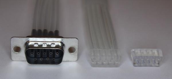
We have developed microfluidic connectors in two different configurations: surface-mounted connectors (female, interfacing with microchannels in microfluidic devices), and tubing-mounted connectors (male or female, interfacing with tubing) as shown in Figure 1. The female surface-mounted connector is directly plasma-bonded to the microfluidic device of interest, providing a standardized interface.
Figure 1.
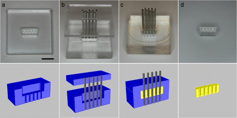
The female surface-mounted connector is fabricated using the process shown in Figure 2. A mold (Figure 2a) was fabricated by milling three pieces of poly(methyl methacrylate) (PMMA). The bottom piece of PMMA, which is 3.175 mm thick, has holes corresponding to the position of the pins on the D-sub connector. The middle piece of PMMA, 6.35 mm thick, is cut in the shape of the female D-sub manifold, shrunk by 1 mm in all directions to facilitate easy attachment and removal from the complementary male housing. The two pieces are bonded using Weld-On 4 Acrylic Cement (IPS Corporation). The lid of the mold is identical to the bottom piece of the mold. The mold is coated with trichloro(1,1,2,2-perfluorooctyl)silane (Sigma-Aldrich) in a vacuum dessicator to facilitate easy removal of the connector from the mold after curing. Hollow 20 gauge metal pins are obtained by cutting the ends off of 1.5” blunt needles with luer hubs (Amazon Supply). The lid of the mold is aligned over the bottom of the mold, and the metal pins are then fed through the holes in the mold (Figure 2b). PDMS (Sylgard 184, 10:1 monomer:curing agent) is mixed and degassed. The lid of the mold is then lifted away from the bottom of the mold to create a gap so that PDMS can be poured into the mold. The PDMS is degassed again, and then the lid of the mold is then pushed onto the bottom of the mold (Figure 2c). The PDMS is cured in an oven at 70°C for at least 4 hours. The connector is then removed from the mold (Figure 2d). This process results in a PDMS block in the shape of a female D-sub connector with holes in the positions of the pins.
Figure 2.
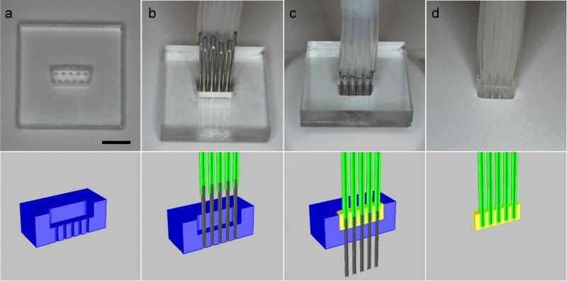
The female cable connector is fabricated using the process shown in Figure 3. Hollow pins are inserted into the mold shown in Figure 3a. Clean, dry silicone tubing (Cole-Parmer, 0.76mm ID) of the desired length is placed over the pins (Figure 3b). PDMS is then poured into the mold. The silicon tubing is pushed down such that it is embedded in the PDMS (Figure 3c). The PDMS is cured in an oven at 70°C for at least 4 hours. The assembly is then removed from the mold. The resulting structure, pictured in Figure 3d, is a PDMS block in the shape of a female D-sub connector with tubing extending from the block. Because the female cable connector does not require a smooth surface for plasma bonding like the female surface-mounted connector, the mold can be milled out of a single 9.525 mm thick piece of PMMA. Alternatively, the connector can be molded directly out of a male D-sub housing, but the resulting connector produces a snugger fit and is more difficult to attach and remove.
Figure 3.
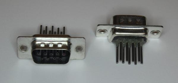
The male connector can be fabricated simply by inserting hollow metal pins into a standard male D-sub connector housing and fixing them in place with epoxy, as shown in Figure 4. Silicone or Tygon tubing of appropriate inner diameter is connected to the pins. These basic structures can be assembled into a variety of interfacing structures such as male-male, male-female, and female-female tubing connectors and adapters.
Figure 4.
Application
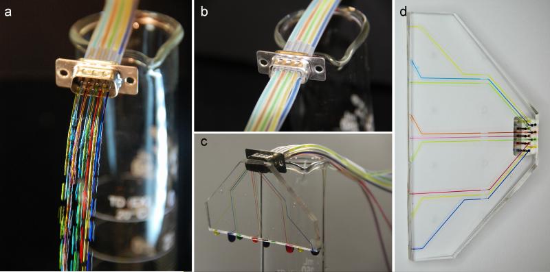
We demonstrate the D-sub connector system using a simple PDMS microfluidic device with nine fluidic inputs, as shown in Figure 5. A 9-channel male connector was fabricated using the protocol above. It was attached to reservoirs with different colors of food coloring to visualize the different fluidic inputs. We demonstrate that it can be plugged into a female tubing connector (Figure 5b). To illustrate how the connector system can be used with planar microfluidic devices, we fabricated a simple device with a surface-mount D-sub connecter that interfaces with nine microfluidic channels (Figure 5c). When the male connector is plugged into the device, the fluidic inputs flow through the connector into the channels. After use, the device can easily be unplugged (Figure 5d).
Figure 5.
Silicone-metal contacts are widely used for fluidics interfacing because the combination of silicone’s hydrophobicity and elasticity provides a good seal; silicone’s large Young’s elastic modulus provides good durability of the male-female plug after repeated cycles. We have observed that our interfaces seal well under normal device operation involving a small number of plugging and unplugging cycles. Tests of long-term durability are ongoing. In order to verify that the connector system does not leak, we bonded the surface-mount connector to a piece of PDMS with no channels to form dead-end connections. The test device was plugged into a male connector and submerged in water. Pressurized air was applied to the device while monitoring the water around the connector for the appearance of bubbles. We tested the device at pressures up to 15 PSI and did not observe any bubble formation. The male-female tubing connection was tested by clamping the silicone tubing from the female connector shut and applying pressurized air. No bubble formation was observed at pressures up to 15 PSI.
Conclusions
We have demonstrated a microfluidic connector system based on existing D-sub connector technology standards. This standard consists of a D-shaped metal shield surrounding two or more parallel rows of pins (for the male connector) or sockets (for the female connector) in a 9-, 15-, 25-, 37-, or 50-pin configuration. Here we have demonstrated the replica-molding of a 9-pin microfluidic D-sub connector using readily-available, low-cost consumables. The findings can be extrapolated to the molding of D-sub connectors of any other size. Our novel microfluidic connector addresses the need for simple, low-cost, standardized connectors that are required in clinical settings and for interfacing microfluidic devices with large numbers of external inputs.
references
- 1.Kortmann H, Blank LM, Schmid A. Lab on a Chip. 2009;9:1455. doi: 10.1039/b820183h. [DOI] [PubMed] [Google Scholar]
- 2.Megens M, Dittmer W, de Witz C, van Iersel B. Journal of Micromechanics and Microengineering. 2009;19:015015. [Google Scholar]
- 3.Bhagat AAS, Jothimuthu P, Pais A, Papautsky I. Journal of Micromechanics and Microengineering. 2007;17:42–49. [Google Scholar]
- 4.Christensen AM, Chang-Yen DA, Gale BK. Journal of Micromechanics and Microengineering. 2005;15:928–934. [Google Scholar]
- 5.Mosadegh B, Bersano-Begey T, Park JY, Burns MA, Takayama S. Lab on a Chip. 2011;11:2813. doi: 10.1039/c1lc20387h. [DOI] [PubMed] [Google Scholar]
- 6.Cooksey GA, Plant AL, Atencia J. Lab on a Chip. 2009;9:1298. doi: 10.1039/b820683j. [DOI] [PubMed] [Google Scholar]
- 7.Chen H, Acharya D, Gajraj A, Meiners J-C. Analytical Chemistry. 2003;75:5287–5291. [Google Scholar]
- 8.Chen A, Pan T. Lab on a Chip. 2011;11:727. doi: 10.1039/c0lc00384k. [DOI] [PubMed] [Google Scholar]
- 9.Chen A, Pan T. Biomicrofluidics. 2011;5:046505. doi: 10.1063/1.3670368. [DOI] [PMC free article] [PubMed] [Google Scholar]
- 10. http://www.microliquid.com/microfluidic-products/chip-holders.
- 11. http://www.micronit.com/footer/technologies/microfluidics/microfluidic-connections/
- 12. http://products.labsmith.com/fluid-control-and-connectors/#.URU2POg35E4.
- 13. http://www.dolomite-microfluidics.com/en/products/multiflux.
- 14.van Heeren H. www.microfluidicsinfo.com/standards1.pdf.
- 15.Fredrickson CK, Fan ZH. Lab on a Chip. 2004;4:526. doi: 10.1039/b410720a. [DOI] [PubMed] [Google Scholar]
- 16.Mark D, Haeberle S, Roth G, von Stetten F, Zengerle R. Chemical Society Reviews. 2010;39:1153. doi: 10.1039/b820557b. [DOI] [PubMed] [Google Scholar]


