

Cells can sense surface topography of the surround extracellular matrix (ECM) and can respond to these physical cues by altering their alignment and migration.[1,2] Furthermore, these topographic features can manipulate cell proliferation and differentiation. The fundamental mechanisms of these cell-surface interactions are still not fully understood. Over the last two decades, due to the growing interests in tissue engineering, significant advances have emerged in microfabrication techniques for generating well-defined surface topographies that influence cellular responses at the micro- and nanoscale.[3] For instance, endothelial cells showed restricted orientation and alignment corresponding to microgroove features.[4] Additionally, it has been demonstrated that microstructures displaying stripes, squares, and spiral geometries influence endothelial cells orientation and fibrillin.[5] In another study, fibroblasts responded to micropatterned pits of varying diameters by altering their migration and proliferation according to the topography.[6]
A growing body of literature has demonstrated that the spatial patterning of cellular behaviors, such as proliferation and differentiation, is believed to be important during tissue development.[7–9] The pattern may be induced by soluble and diffusible morphogens, adhesion to the ECM and mechanical stress. Among them, mechanical stress recently has been increasingly recognized as an important player in cellular behaviors and morphogenesis.[10] The mechanical stress can arise from the cytoskeletal tension within tissues, which can be determined by the geometry of the tissue, since the formation of any architectural structure is the consequence of a dynamic process towards equilibrium of physical forces.[8,9] To our knowledge, most of the studies so far have utilized two dimensional (2D) platforms with simple geometries such as grooves and ridges, an inherent limitation of previous microfabrication techniques. However, cells grown on 2D surface can lose their essential cellular functions that are in the tissues, display considerably different morphology, and differ in cell-cell communication, cell-ECM interactions.[11,12] This issue can only be solved by using 3D cell culture systems. It can mimic the tissue-specific architecture, mechanical cues and cell-cell interactions, which might be either lost or impaired in 2D systems, and thus bridges the gap between cell culture and live tissue.[13,14] It was reported that the introduction of specific 3D conformations may guide internal mechanical stress patterns that could further impact cell behavior.[9]
In this work, we demonstrate a novel 3D biofabrication approach based on a digital-mirror device (DMD), called dynamic optical projection stereolithography (DOPsL) (Figure 1) If compared to other emerging nanofabrication technologies, e.g. scanning electron-beam lithography, focused ion-beam lithography, and two-photon polymerization, the DMD-based lithography technologies provides superior processing speed (as it manipulates images using a million pixels rather than one focused point) and thus is more suitable for manufacturing large-area microstructures. Although the DMD based lithography has been well recognized as a promising maskless optical lithography (MOL) technology,[15] the report on DMD based stereolithography is still rare. Here we propose the DMD based DOPsL for biofabrication of complex 3D extracellular microenvironments. Compared to previous DMD-biofabrication methods, which are limited to simple geometries,[16–18] this robust and versatile platform has implications in studying 3D geometric and mechanical cues in vitro as well as generating complex 3D designer scaffolds for implantable constructs in vivo.
Figure 1.
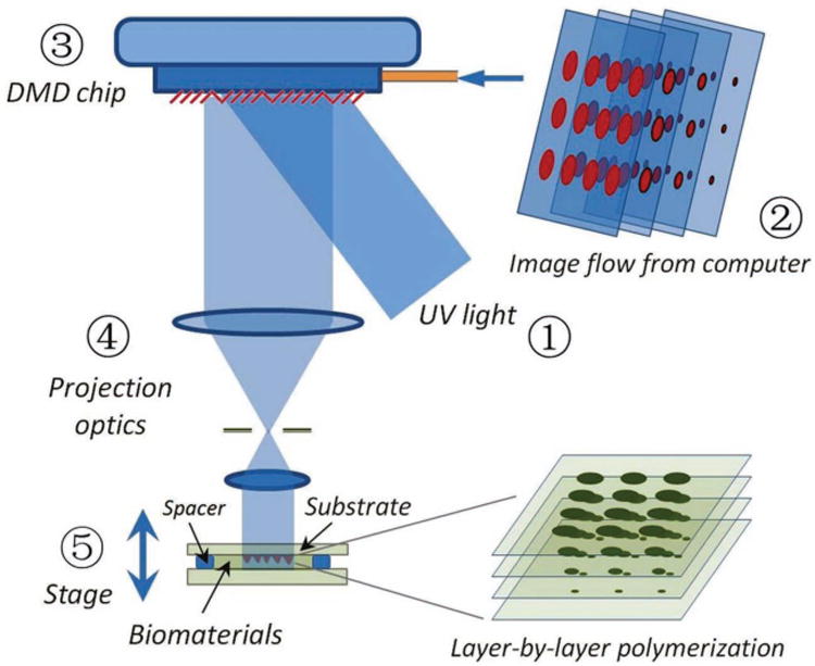
Schematic Diagram of Dynamic Optical Projection Stereolithography: UV-light illuminates the DMD mirror system, which generates an optical pattern according to the image flow from the control computer. The optical pattern is projected through optical lens and onto the photosensitive biomaterial to fabricate a 3D scaffold.
Extracellular microenvironment fabrication
We used the DOPsL fabrication platform to create various extracellular microenvironments. To highlight the versatility of the system, we fabricated various shapes and topographic features that have potential applications in chip-based cell research (Figure 2). We used a PEGDA-based prepolymer solution as lithographic material. A microwell CAD model was sliced into 100 layers and processed through the DOPsL setup. Samples were fabricated after 12 seconds of UV-light exposure, which is significantly faster than other stereolithography techniques, e.g. two-photon polymerization which take several hours or longer to fabricate a similar 3D sample. Four kinds of microwells, including step-wise, spiral, embryo-like and flower-like microwells, were fabricated on a single chip (Figure 2b-e). The surfaces of stepwise, spiral and flower-like microwells were very smooth, whereas the surfaces of embryo-like microwells were somewhat rough due to proximity effects. Inverses of these microstructures were also developed (Figure 2f-i). The size of the bio-chip is around 4.6 mm × 3.5 mm with each microwell of approximately 200 μm. Through step and print, the bio-chip size can easily be increased to cm even larger. These microwell bio-chips could be used as biomimetic in vitro microenvironments for cell biology research.
Figure 2.

SEM Images of the Fabricated 100%-PEGDA Microwells and Microarchitectures. a) The fabricated chip with various microstructured wells: b) stepwise, c) spiral, d) embryo-like and e) flower-like. (f-i) are the inverse of the wells, demonstrating the versatility of the biofabrication system.
One of the distinct features of the DOPsL is the light based, non-contact fabrication scheme that is capable of manipulating soft biomaterials. In the experiments, we successfully fabricated ultra-soft hemispheres using 20% PEG prepolymer solution, a common biomaterial and hydrogel precursor. In order to characterize the features of hydrogel microstructures with high water content, we entrapped a fluorescent probe inside the scaffold and then used con-focal microscopy to facilitate imaging. 0.02 wt% FITC-labeled polystyrene beads (200 nm size) were mixed with the 20% PEGDA (MW 700) prepolymer solution before the UV exposure. Scaffolds were fabricated in a similar manner as previously described in Section 3.1 and analyzed under confocal microscopy. In Figure 3a the fabricated hemisphere structure was visualized using 3D volume rendering of confocal z-stacks via Image-J software. One can see that the surfaces of hemispheres are very regular and smooth which means the DOPsL platform can process well ultra-soft biomaterial for tailoring complex extracellular environments.
Figure 3.

Characterization of the Fabricated 20%-PEGDA Hemisphere Microstructures. a) A 3D reconstruction via Image J displayed the hemisphere structure fabricated using DOPsL with 20% w/v PEGDA plus fluorescent probes. b) Fluorescent intensity heat map of the chemically linked fluorescent probes via Image J indicated a gradient of cross-linking inside the scaffold, which showed great consistency with the simulation results (inset).
Characterization of stiffness profile
Due to the importance of ECM stiffness in directing cell morphology and development, fluorescein amidite-labeled monoacryloyl-RGD (Arginine-Glycine-Aspartic Acid) peptide (FAM-RGD) is used as acrylated fluorescent probe to evaluate the cross-linking profile, and therefore stiffness, inside our fabricated scaffolds.
FAM-RGD was modified by acrylate-PEG-succinimidyl valerate to become photopolymerizable. We used DOPsL to fabricate scaffolds with the macromer solution containing approximately 0.12mM monoacryloyl-PEG-RGD-FAM. After fabrication, the scaffolds were rinsed extensively in PBS overnight before taking the confocal microscopy images. The heat map generated according to the fluorescent intensity indicated a gradient of cross-linking inside the scaffold (Figure 3b). The fluorescent signal came from the monoacryloyl probe chemically linked to the scaffold during the polymerization, and thus is directly related to the cross-linking density. The fluorescent signals showed a decreasing trend from the center towards the outside of the structure, with the strongest signal in the center, matching with simulated results (Figure 3b outset). In the fabrication of the microstructures, the UV penetration depth was relatively deep as we used a low-concentration dye. Therefore, the optical pattern for exposing the top layer affected the other layers below in an additive manner and resulted in a gradient stiffness profile (due to a gradient in the degree of cross-linking).
Cell-material interactions
To test the cellular response in vitro, we seeded two cell types (HUVECs and NIH-3T3) onto our fabricated structures and monitored cell morphology and cell-material interactions. HUVECs cells were seeded onto the gradient hemisphere structures consisting of 15% GELMA, which is a widely used scaffold material for tissue engineering applications due to its support of rapid cellular proliferation and reorganization. The cells were stained for F-actin and nuclei and fluorescent images were taken using confocal microscopy. After 4 days of culture, HUVECs recognized the geometries introduced, and displayed nice alignment around the circumference of the lower part of the hemispheres (Figure 4a-b). Moreover, cord-like structures were also observed (indicated by arrows in Figure 4c). The cells in the gaps between the hemispheres showed normal morphology similar to normal 2D culture on a flat surface (Figure 4d), which is interestingly different compared to the cells growing on the curvature. By providing the HUVECs with geometry cues in addition to cell adhesion sites, we demonstrated the potential to manipulate HUVECs morphology and guide multicellular organization.
Figure 4.

Culture of HUVECs on the 15%-GelMA Hemisphere Structures. a) Multi-channel z-projection image by confocal microscope displayed HUVECs growing on gradient hemisphere structures after 4 days of culture. b) A higher magnification z-projection confocal image showed multicellular organizations on the hemisphere structures. c) Z sectioning image close to the bottom of the scaffold illustrated the cord-like structures around the circumference as indicated by the arrows. d) Z sectioning image at the bottom of the structure showed normal cell morphology in the gaps between hemisphere structures as highlighted in the box region. F-actin (red) was stained with rhodamine phalloidin and the nuclei (blue) were counterstained with Hoechst.
To further assess our platform, we performed similar cell study with NIH-3T3 mouse embryonic fibroblast cells on the microwell structures (Figure 5a). 3T3 cells were harvested and seeded onto the microwell structures fabricated with 20% PEGDA (MW 700) supplemented with 2mM acrylol-PEG-RGDS as the cell adhesion ligand. Cells were cultured for 4 days before fixing and stained for F-actin and nuclei. Similar to the natural polymer GELMA scaffolds, scaffolds consisting of the synthetic material, PEGDA functionalized with RGDS, were also capable of supporting cells adhesion and proliferation (Figure 5b). Interestingly, cells were restricted to inside the microwells of the size around 250 microns, and were well aligned on the walls of the microwells and formed complex multicellular structures. Using confocal microscopy, we reconstructed the multicellular structure within the fabricated micro-structures. 3D renderings revealed a bowl-like multi-cellular structure inside the wells, which closely mimicked the feature of microwell itself (Figure 5c). Furthermore, images at different z-positions illustrated that cells could sense and respond to the varying sizes of the opening, and thus form different multicellular structures (Figure 5d-f). At the top of the construct (well size ∼ 250 microns), cells followed very strict alignment on the edge of the well without cell-cell interactions in the pocket area (Figure 5d). In moving to a lower z-position, the size of the well opening effectively decreased. In the middle of the construct (well size ∼ 160 microns), increasing cell-cell interactions and more complex multicellular structure were detected in the pocket area (Figure 5e). At the bottom of the microwell construct, we noticed significantly different cell-cell organizations. The cell alignment at the edge was disrupted and the cells were prone to form a cell sheet to cover the pocket area with strong cell-cell interactions (Figure 5f). With the alteration of the size of the well opening, we demonstrated the potential to guide and manipulate cell-cell interactions and multicellular organization.
Figure 5.

Culture of 3T3 Cells on the 20% PEGDA Stepwise Microwells. a) Schematic view of the cell culture on stepwise microwells. b) Confocal z-projection image of 3T3 cell culture after 4 days illustrated the microwells scaffold can support cell adhesion and proliferation. c) 3D reconstruction of 3T3 cells on the microwells scaffold via Image J displayed bowl-like multicellular organizations inside the pocket area of the wells, which indicated the geometric guidance of the scaffolds. d–f) The z-sectioning images from the top to the bottom of the scaffold, showing different cell-cell organizations corresponding to the altering scaffold geometry at different z positions. F-actin (red) was stained with rhodamine phalloidin and the nuclei (blue) were counterstained with Hoechst.
To conclude, we have demonstrated a new stereo-biofabrication method called DOPsL. We were able to rapidly (within seconds) fabricate complex 3D microarchitectures with designer geometries using soft, degradable biomaterials (20% PEDGA and GelMA), though the system can be adapted to any photosensitive biomaterial and any CAD design, a key feature of the versatile platform. The in vitro results revealed that the scaffolds have promising capability to guide and manipulate cell-cell interactions and multicellular organizations. Such a rapid biofabrication technology has strong potential to evolve chip-based cell research from 2D substrates to 3D biomimetic microenvironments, and additionally, to generate designer 3D scaffolds for tissue engineering implants.
Experimental Section
Figure 1 shows the schematic diagram of the proposed DOPsL platform. The system mainly consists five parts: 1) UV light source; 2) computer for sliced image-flow generation and system synchronization; 3) DMD chip for optical pattern generation; 4) projection optics; 5) stage for sample position control.
The light beam from the UV source is collimated and illuminates the DMD chip. As a spatial light modulator, the DMD chip (constituted by approximately one million micro-mirrors) modulates the light beam to generate an optical pattern identical to that transmitted from the control computer. Thereafter, the optical pattern is projected into photosensitive material through a projection lens system. In order to make the sample exposed at the right image plane, a computer controlled stage is used to position the sample (holder) at specific locations. The key part of such a fabrication scheme is the DMD chip. The micro-mirrors of the DMD chip can be flipped under computer control in extremely high speed (the whole pattern of micro-mirrors can be switched over in 30 μs).
In order to make a complex 3D microstructure, a custom-designed model is built by using CAD technology and then sliced into a series of digital images. With a control computer and in-house developed software, those images are automatically loaded one-by-one into the DMD chip and then projected into the photoresist to form 3D microstructures through a continuous, layer-by-layer polymerization process. In order to project the image on the corresponding layer, the sample (holder) is synchronically positioned by using a motorized stage. Compared with regular projection stereolithography, the DOPsL method offers much more fabrication flexibility and faster process speed due to the use of abundant virtual masks. In principle there is no limitation of structure geometry for this method. However, current setup is not recommended to fabricate 3D suspended microstructures due to the relatively long depth of focus.
Prepolymer solution preparation
Poly (ethylene glycol) diacrylate (PEGDA, Mw = 700), acrylic acid (AA), 2,2,6,6-tetramethylpiperidine 1-oxyl (TEMPO, free-radical quencher) and 2-Hydroxy-4-methoxy-benzophenon-5-sulfonic acid (HMBS) were purchased from Sigma-Aldrich. Photoinitiator Irgacure 2959 and TINUVIN 234 UV-dye were obtained from Ciba Chemistry. TINUVIN 234 and HMBS, which were used in 100% PEGDA and 20% PEGDA prepolymer solution respectively as UV-absorbing agents, were used to reduce the curing depth of the monomers and adjust the thickness of the microstructures in the fabrication process. TEMPO, on the other hand, enhances the contrast of the UV-curing process and optimizes feature resolution at the projection plane. To prepare the 100% PEGDA solution, first, 5% (w/v) acrylic acid (AA) was mixed with 95% (w/v) PEGDA. To this solution, 1% (w/v) Irgacure 2959 was dissolved thoroughly at 35 °C for one hour, with subsequent additions of 0.15% (w/v) of TINUVIN 234, and 0.01% (w/v) of TEMPO for one hour each. Similarly, 20% PEGDA solution was prepared by mixing 1% (w/v) AA, 19% (w/v) PEGDA, 1% (w/v) Irgacure 2959, 0.1% (w/v) of HMBS, and 0.01% (w/v) of TEMPO in a phosphate buffer saline (PBS) solution.
Gelatin methacrylate (GelMA) was synthesized as described previously.[16] The prepolymer solution was prepared by mixing 15% (w/v) GelMA with 1% (w/v) Irgacure 2959, 0.1% (w/v) HMBS, 0.01% TEMPO in PBS with the presentation of calcium carbonate microparticles to increase the stiffness of the structure.
Supplementary Material
Acknowledgments
The project described was supported in part by Award Number R01EB012597 from the National Institute of Biomedical Imaging And Bioengineering and grants (CMMI-1130894, CMMI-1120795) from the National Science Foundation. A.P. Z. was supported by the U.S. National Science Foundation I2CAM International Materials Institute Award, Grant DMR-0844115 and National Natural Science Foundation of China (51028501). The UCSD Neuroscience Microscopy Shared Facility was supported by Grant P30 (NS047101). The authors would thank Dr. Shu Chien of UCSD for providing human umbilical vein endothelial cell (HUVEC) as a gift.
Footnotes
Supporting Information: Supporting Information is available from the Wiley Online Library or from the author.
Contributor Information
Dr. A. Ping Zhang, Email: zhangap@zju.edu.cn, Department of NanoEngineering, University of California, San Diego, CA 92093, USA, Centre for Optical and Electromagnetic Research, State Key Laboratory of Modern Optical Instrumentation, Zhejiang University, Hangzhou 310058, P. R. China.
Dr. Xin Qu, Department of NanoEngineering, University of California, San Diego, CA 92093, USA
Dr. Pranav Soman, Department of NanoEngineering, University of California, San Diego, CA 92093, USA
Dr. Kolin C. Hribar, Department of NanoEngineering, University of California, San Diego, CA 92093, USA
Dr. Jin W. Lee, Department of NanoEngineering, University of California, San Diego, CA 92093, USA
Prof. Shaochen Chen, Email: shc064@ucsd.edu, Department of NanoEngineering, University of California, San Diego, CA 92093, USA.
Prof. Sailing He, Centre for Optical and Electromagnetic Research, State Key Laboratory of Modern Optical Instrumentation, Zhejiang University, Hangzhou 310058, P. R. China
References
- 1.Hoffman-Kim D, Mitchel JA, Bellamkonda RV. Annu Rev Biomed Eng. 2010;12:203–31. doi: 10.1146/annurev-bioeng-070909-105351. [DOI] [PMC free article] [PubMed] [Google Scholar]
- 2.Anselme K, Bigerelle M. Int Mater Rev. 2011;56:243. [Google Scholar]
- 3.Tay CY, Irvine SA, Boey FYC, Tan LP, Venkatraman S. Small. 2011;7:1361. doi: 10.1002/smll.201100046. [DOI] [PubMed] [Google Scholar]
- 4.Bettinger CJ, Orrick B, Misra A, Langer R, Borenstein JT. Biomaterials. 2006;27:2558–65. doi: 10.1016/j.biomaterials.2005.11.029. [DOI] [PubMed] [Google Scholar]
- 5.Rossi A, Pasqui D, Barbucci R, Gerli R, Weber E. Tissue Eng. 2009;A15:525–33. doi: 10.1089/ten.tea.2007.0421. [DOI] [PubMed] [Google Scholar]
- 6.Berry CC, Campbell G, Spadiccino A, Robertson M, Curtis ASG. Biomaterials. 2004;25:5781–8. doi: 10.1016/j.biomaterials.2004.01.029. [DOI] [PubMed] [Google Scholar]
- 7.Nelson CM, Jean RP, Tan JL, Liu WF, Sniadecki NJ, Spector AA, Chen CS. Proc Natl Acad Sci USA. 2005;102:11594–9. doi: 10.1073/pnas.0502575102. [DOI] [PMC free article] [PubMed] [Google Scholar]
- 8.Gomez EW, Chen QK, Gjorevski N, Nelson CM. J Cell Biochem. 2010;110:44–51. doi: 10.1002/jcb.22545. [DOI] [PMC free article] [PubMed] [Google Scholar]
- 9.Ingber DE. Proc Natl Acad Sci USA. 2005;102:11571–2. doi: 10.1073/pnas.0505939102. [DOI] [PMC free article] [PubMed] [Google Scholar]
- 10.Wozniak MA, Chen CS. Nat Rev Mol Cell Bio. 2009;10:34. doi: 10.1038/nrm2592. [DOI] [PMC free article] [PubMed] [Google Scholar]
- 11.Pampaloni F, Reynaud EG, Stelzer EHK. Nat Rev Mol Cell Biol. 2007;8:839. doi: 10.1038/nrm2236. [DOI] [PubMed] [Google Scholar]
- 12.Tibbitt MW, Anseth KS. Biotechnol Bioeng. 2009;103:655. doi: 10.1002/bit.22361. [DOI] [PMC free article] [PubMed] [Google Scholar]
- 13.Khademhosseini A, Langer R, Borenstein J, Vacanti JP. Proc Natl Acad Sci USA. 2006;103:2480. doi: 10.1073/pnas.0507681102. [DOI] [PMC free article] [PubMed] [Google Scholar]
- 14.Zorlutuna P, Annabi N, Camci-Unal G, Nikkhah M, Cha JM, Nichol JW, Manbachi A, Bae H, Chen S, Khademhosseini A. Adv Mater. 2012;24:1782. doi: 10.1002/adma.201104631. [DOI] [PMC free article] [PubMed] [Google Scholar]
- 15.Menon R, Patel A, Gil D, Smith HI. Mater Today. 2005;8:26. [Google Scholar]
- 16.Lu Y, Mapili G, Suhali G, Chen S, Roy K. J Biomed Mater Res A. 2006;77A:396. doi: 10.1002/jbm.a.30601. [DOI] [PubMed] [Google Scholar]
- 17.Wang S, Foo CWP, Warrier A, Poo MM, Heilshorn SC, Zhang X. Biomed Microdevices. 2009;11:1127. doi: 10.1007/s10544-009-9329-1. [DOI] [PMC free article] [PubMed] [Google Scholar]
- 18.Gauvin R, Chen YC, Lee JW, Soman P, Zorlutuna P, Nichol JW, Bae H, Chen S, Khademhosseini A. Biomaterials. 2012;33:3824. doi: 10.1016/j.biomaterials.2012.01.048. [DOI] [PMC free article] [PubMed] [Google Scholar]
Associated Data
This section collects any data citations, data availability statements, or supplementary materials included in this article.