Abstract
The alignment of a lower-limb prosthesis is critical to the successful prosthetic fitting and utilization by the wearer. Loads generated by the socket applied to the residual limb while walking are thought to be different in transfemoral and knee-disarticulation prostheses. The aim of this case series was to compare the socket reaction moments between transfemoral and knee-disarticulation prostheses and to investigate the effect of alignment changes on them. Two amputees, one with a transfemoral prosthesis and another with a knee-disarticulation prosthesis, participated in this study. A Smart Pyramid™ was used to measure socket reaction moments while walking under 9 selected alignment conditions; including nominally aligned, angle malalignments of 6° (flexion, extension, abduction and adduction) and translation malalignments of 15 mm (anterior, posterior, medial and lateral) of the socket relative to the foot. This study found that the pattern of the socket reaction moments was similar between transfemoral and knee-disarticulation prostheses. An extension moment in the sagittal plane and a varus moment in the coronal plane were dominant during stance under the nominally aligned condition. This study also demonstrated that alignment changes might have consistent effects on the socket reaction moments in transfemoral or knee-disarticulation prostheses. Extension or posterior translation of the socket resulted in increases in an extension moment, while abduction or lateral translation of the socket resulted in increases in a varus moment. The socket reaction moments may potentially serve as useful biomechanical parameters to evaluate alignment in transfemoral or knee-disarticulation prostheses.
Keywords: Ankle, Amputation, Kinetics, Knee, Malalignment
1. Introduction
Successful lower-limb prosthetic fittings partly depend on the spatial relationship of the socket relative to other components (i.e. knee, foot) of the prosthesis: commonly defined as the alignment (Zahedi et al., 1986). The prosthesis is tuned through bench, static and dynamic alignment procedures. Initial flexion and adduction angles are built into the prostheses in bench alignment (Berger and Fishman, 1997). A height and general orientation of the prosthetic components are adjusted while standing in static alignment. Dynamic alignment is a final iterative tuning process that includes clinical observation of walking and collaborative communications with the amputee. Even with these steps the acceptable range of alignment varies among prosthetists (Zahedi et al., 1986), inter-rater repeatability of observational gait analysis is poor (Hillman et al., 2010) and perception of alignment is not entirely reliable in amputees (Boone et al., 2012).
Loads generated by the socket applied on the residual limb have been thought to be different in transfemoral and knee-disarticulation prostheses (Cummings and Russ, 2004; Hughes, 1983). It is thought that in transfemoral prostheses, the center of rotation of the socket (support point) is located proximally around the ischial tuberosity due to pelvic weight bearing. While in knee-disarticulation prostheses, the center of rotation of the socket is thought to be located distally at the end of the socket due to weight bearing on the end of the femur and the exclusion of the ischial support. Therefore, in transfemoral prostheses, the socket is thought to rotate against the femur distally during mid-stance, while, in the knee-disarticulation prosthesis, it is thought to rotate against the femur proximally. However, these claims are clinical concepts that have not been experimentally validated. Knee disarticulation amputations have been generally preferred over transfemoral amputation in children because it can provide a weight-bearing residual limb without potential complications caused by bone overgrowth (Krajbich, 1998).
Loads exerted by the prosthetic socket can be measured directly using various instruments (Boone et al., 2013; Frossard et al., 2003; Kobayashi et al., 2012; Neumann et al., 2013; Sanders et al., 1997) or indirectly using inverse dynamics in a gait lab (Dumas et al., 2009; Frossard et al., 2011; Stephenson and Seedhom, 2002). Direct measurement enables the continuous measurement of kinetics of gait anywhere and has additional potential for both clinical and research use.
In transtibial prostheses, alignment changes had consistent effects on socket reaction moments (Boone et al., 2013; Kobayashi et al., 2013). Socket reaction moments are moments acting about the geometric center of the socket and transferred through the prosthesis at the distal end of the socket while walking (Kobayashi et al., 2012). Little is known about the effect of alignment changes on the socket reaction moments in transfemoral and knee-disarticulation prostheses. In transfemoral prostheses an increase in hip extensor moments was demonstrated when the prosthetic knee was shifted anteriorly (Schmalz et al., 2002). The aim of this case series was to compare the socket reaction moments between transfemoral and knee-disarticulation prostheses and to investigate the relationship between the alignment and socket reaction moments.
2. Methods
2.1 Participants
Two amputees participated in this study. One participant was a male adult amputee (Age: 42-year-old; Height: 1.73 m; Mass: 77 kg; Residual limb length: 38cm; K-Level: 3) using a transfemoral prosthesis (participant with TFP) with an ischial containment socket. His right leg was amputated 12 years prior due to necrotizing fasciitis caused by trauma. The knee joint was a Mauch Knee (Ossur, Reykjavik, Iceland), while the foot was a Seattle Light Foot (Trulife, Dublin, Ireland). The other participant was a male pediatric amputee (Age: 12-year-old; Height: 1.42 m; Mass: 33 kg; Residual limb length: 28cm; K-Level: 4) using a knee-disarticulation prosthesis (participant with KDP) with an end-weight-bearing socket without an ischial support. His right leg was amputated 10 years prior due to congenital fibular hemimelia. The knee joint was a Total Knee Junior (Ossur, Reykjavik, Iceland), while the foot was a Renegade foot (Freedom Innovations, Irvine, CA). This study was approved by the institutional review board governing the institution, and a consent/assent was obtained.
2.2 Apparatus
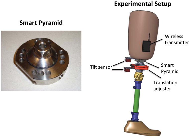
A Smart Pyramid™ (Height: 3.22 cm; Mass: 0.14 kg) (Orthocare Innovations, Oklahoma City, OK, US) was used to measure socket reaction moments (Figure 1). The Smart Pyramid is an instrumented prosthetic pyramid adaptor with 8 strain gauges. The data collected from the Smart Pyramid were sent to the computer wirelessly at a sampling frequency of 100 Hz via Bluetooth. The moment output of the Smart Pyramid was highly linear with coefficients of determination of R2=0.998 for the sagittal moment and R2=0.996 for the coronal moment. The measured sagittal moments showed a root mean square error of 2.08 % and the coronal moments at 2.80 %. Biaxial MEMS tilt sensors (CXT-02, Crossbow Technologies, San Jose, USA) were used to measure angle alignment changes, while millimeter scales on the translation adjuster (10A40/A, F.G. Streifeneder KG, Emmering, Germany) were used to measure translation alignment changes (Boone et al., 2013) (Figure 1).
Figure 1.
Smart Pyramid™ and experimental setup.
2.3 Protocol
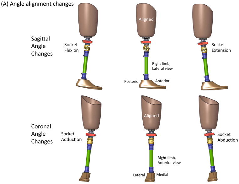
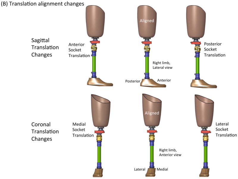
The alignment of their prosthesis was dynamically tuned to the satisfaction of the prosthetist and the participant. From this nominally aligned condition, angle perturbations of 6° (flexion, extension, abduction, and adduction) and translation perturbations of 15mm (anterior, posterior, lateral, and medial) were induced in a random order (Figure 2). This is within the range of alignment changes made during regular adjustments in the clinic. The participant was instructed to walk down a 10-meter hallway at a comfortable walking speed under the nine alignment conditions.
Figure 2.
Description of prosthetic alignment: (A) Angle alignment changes, (B) Translation alignment changes.
2.4 Data analysis
The socket reaction moment data were interpolated with a cubic spline function, and the whole gait cycle was normalized to 100% with increments of 1% each. The gait events were identified based on the timing of the axial force. The socket reaction moments of 3 gait cycles were normalized to body mass and averaged. Gait initiation and termination steps were excluded from the analysis by selecting 3 steps in the middle of the trial. Maximum extension socket reaction moments and maximum varus moments were extracted at each alignment condition. Cadence (steps/min) was also calculated based on the socket reaction moment data of the 3 gait cycles.
3. Results
3.1. Effect of sagittal alignment changes on sagittal moments and cadence
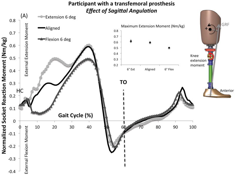
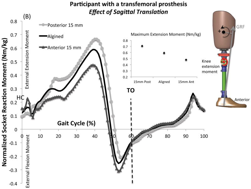
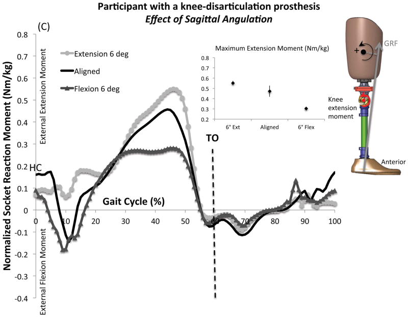
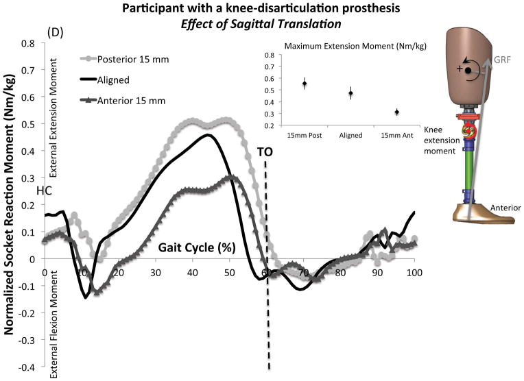
The mean and standard deviations of normalized maximum extension socket reaction moments and cadence under each alignment condition are presented in Table 1. Figure 4 shows the mean normalized sagittal socket reaction moments across a gait cycle. Both angle and translation alignment changes revealed consistent changes in the socket reaction moments. An extension moment was dominant during stance in both participants under the nominally aligned condition. A flexion moment was observed at early stance and late stance to early swing in the participant with KDP, while the flexion moment was only found at late stance to early swing in the participant with TFP. Cadence ranged from 99 to 106 steps/min and from 97 to 111 steps/min in the participant with TFP and KDP, respectively.
Table 1.
Effect of sagittal alignment changes on the normalized sagittal moments and cadence
| Alignment changes | Maximum Extension Moment (Nm/kg) | Cadence (steps/min) | |||
|---|---|---|---|---|---|
| TFP | KDP | TFP | KDP | ||
| Sagittal angle | 6° Extension | 0.62 (0.03) | 0.55 (0.02) | 100 (3) | 101 (3) |
| Aligned | 0.59 (0.02) | 0.47 (0.05) | 106 (3) | 111 (3) | |
| 6° Flexion | 0.50 (0.01) | 0.30 (0.02) | 99 (2) | 97 (2) | |
| Sagittal translation | 15 mm Posterior | 0.71 (0.02) | 0.55 (0.05) | 106 (1) | 102 (6) |
| Aligned | 0.59 (0.02) | 0.47 (0.05) | 106 (3) | 111 (3) | |
| 15 mm Anterior | 0.48 (0.02) | 0.31 (0.03) | 105 (1) | 99 (3) | |
Mean and standard deviations are provided as mean (SD).
Abbreviations: TFP, participant with a transfemoral prosthesis; KDP, participant with a knee-disarticulation prosthesis
Figure 4.
Effect of sagittal alignment changes on the mean normalized sagittal socket reaction moments: (A) Effect of sagittal angulation in the participant with a transfemoral prosthesis (TFP), (B) Effect of sagittal translation in the participant with TFP, (C) Effect of sagittal angulation in the participant with a knee-disarticulation prosthesis (KDP), (D) Effect of sagittal translation in the participant with KDP. An external extension moment in the sagittal plane was defined as positive. Mean and standard deviations are provided at maximum extension moment under each alignment condition. Maximum values on the graphical display of the moment curves may not match the calculated maximum values [small point and whisker graphs]. The full moment curves contain temporal variability in the peak timing whereas the mean was calculated from each step’s maximum extension moment regardless of timing.
Abbreviations: Ant: anterior, Ext: extension, Flex: flexion, GRF: ground reaction force, HC: heel contact, Post: posterior, TO: toe off,
3.2 Effect of coronal alignment changes on coronal moments and cadence
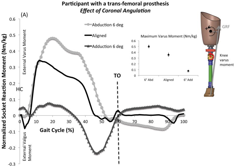
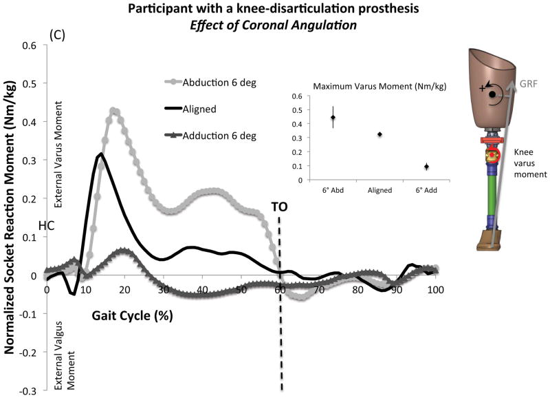
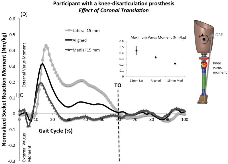
The mean and standard deviations of normalized maximum varus socket reaction moments and cadence under each alignment condition are presented in Table 2. Figure 5 shows the mean normalized coronal socket reaction moments across a gait cycle. Both angle and translation alignment changes revealed consistent changes in the socket reaction moments. A varus moment was dominant during stance in both participants under the nominally aligned condition. A valgus moment at early stance was followed by a varus moment throughout the stance in both participants. Cadence ranged from 100 to 110 steps/min and from 103 to 111 steps/min in the participant with TFP and KDP, respectively.
Table 2.
Effect of coronal alignment changes on the normalized coronal moments and cadence
| Alignment changes | Maximum Varus Moment (Nm/kg) | Cadence (steps/min) | |||
|---|---|---|---|---|---|
| TFP | KDP | TFP | KDP | ||
| Coronal angle | 6° Abduction | 0.50 (0.03) | 0.45 (0.08) | 100 (2) | 107 (3) |
| Aligned | 0.36 (0.04) | 0.32 (0.01) | 106 (3) | 111 (3) | |
| 6° Adduction | 0.08 (0.01) | 0.09 (0.03) | 100 (5) | 103 (7) | |
| Coronal translation | 15 mm Lateral | 0.44 (0.01) | 0.44 (0.08) | 102 (2) | 107 (6) |
| Aligned | 0.36 (0.04) | 0.32 (0.01) | 106 (3) | 111 (3) | |
| 15 mm Medial | 0.34 (0.03) | 0.22 (0.04) | 110 (4) | 111 (4) | |
Mean and standard deviations are provided as mean (SD).
Abbreviations: TFP, participant with a transfemoral prosthesis; KDP, participant with a knee-disarticulation prosthesis
Figure 5.
Effect of coronal alignment changes on the mean normalized coronal socket reaction moments: (A) Effect of coronal angulation in the participant with a transfemoral prosthesis (TFP), (B) Effect of coronal translation in the participant with TFP, (C) Effect of coronal angulation in the participant with a knee-disarticulation prosthesis (KDP), (D) Effect of coronal translation in the participant with KDP. A varus moment in the coronal plane was defined as positive. Mean and standard deviations are provided at maximum varus moment under each alignment condition. Maximum values on the graphical display of the moment curves may not match the calculated maximum values [small point and whisker graphs]. The full moment curves contain temporal variability in the peak timing whereas the mean was calculated from each step’s maximum varus moment regardless of timing.
Abbreviations: Abd: abduction, Add: adduction, GRF: ground reaction force, HC: heel contact, Lat: lateral, Med: Medial, Post: posterior, TO: toe off,
4. Discussion
This case series investigated the relationship between the alignment and socket reaction moments in transfemoral and knee-disarticulation prostheses. The pattern of socket reaction moments was similar for each despite differences in socket design and amputation levels. An extension moment and a varus moment were dominant during stance under the nominally aligned condition. Therefore, the socket was suggested to rotate against the distal femur in the coronal plane during mid-stance in both prostheses. The effect of alignment changes revealed consistent changes in socket reaction moments. Visualization of alignment changes through socket reaction moments may allow clinicians to quantitatively align the prostheses and understand how a residual limb is loaded inside the socket.
Direct measurement of kinetics in amputees gait has been used to evaluate loading and to construct a biomechanical modeling of other prosthetic designs such as an osseointegrated implant (Frossard et al., 2010; Frossard et al., 2008; Lee et al., 2008a). The pattern of moments measured in amputees with an osseointegrated prosthesis appeared similar to that measured in the participants with TFP and KDP, showing peak extension moment around 40% of gait cycle (Lee et al., 2007; Lee et al., 2008b). A flexion moment was generally reported in early stance in amputees with osseointegrated prostheses, but it was only observed in the participant with KDP. Cadence was within the range of individuals with transfemoral amputation (71 to 114 steps/min) reported earlier (Frossard et al., 2010). Socket reaction moments may be affected by gait speed (Goldberg and Stanhope, 2013).
Stability in the sagittal plane is achieved by an extension moment during stance, but an excessive extension moment could cause unnecessary proximal anterior brim pressure with too much stability for an efficient gait. A flexion moment in the early stance could make the knee unstable if the knee does not have a properly tuned stance control feature. However, a flexion moment can be beneficial in providing shock absorption if the knee is stable. An early stance flexion moment was observed in the participant with KDP. This may be attributed to an adjustable flex stance feature of the Total Knee Junior. Stability in the coronal plane is achieved by varus moment during stance. This tends to maintain the adduction of the femur and reduce gait deviations. Socket reaction moments are affected by the inertia of the prosthesis below the Smart Pyramid and the hip extensors during swing. Ability to measure kinetics during swing phase is the advantage of direct measurement. Therefore, socket reaction moments of an acceptable alignment should have proper extension and varus moment during stance and may have a flexion moment at early stance depending on the knee joint. Extension or posterior translation of the socket will move the foot forward relative to the socket, resulting in an increase in an extension moment in the sagittal plane. Abduction or lateral translation of the socket will move the foot medial to the socket, causing an increase in a varus moment in the coronal plane.
Despite technological advancement in lower-limb prosthetics, the prosthetic alignment method has not been changed for many decades. The Smart Pyramid can provide clinicians kinetic information related to the alignment of lower-limb prostheses that otherwise requires a gait laboratory. The Smart Pyramid could be potentially used as a sensing unit to control a microprocessor prosthetic knee or foot. It could also be used to evaluate the various prosthetic components, such as a socket, knee, ankle or foot. Direct measurement techniques could benefit not only clinicians but also engineers and researchers in biomechanics.
5. Conclusion
This study suggested a potential relationship between alignment and socket reaction moments in transfemoral and knee-disarticulation prostheses. Socket reaction moments might serve as useful biomechanical parameters to assess prosthetic alignment. A limitation to this study was the lack of participants. This was a case series with one adult and one pediatric amputee. Some degrees of hip flexion contractures are common. A larger scale study is warranted to confirm the relationship between alignment and socket reaction moments as well as the effect of the contractures in these prostheses with various components and to explore the needs of each population. A future study should focus on the relationship between socket reaction moments and skin quality of the residual limb for evidence-based management of amputees.
Figure 3.
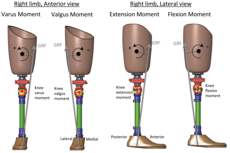
Description of socket reaction moments.
Abbreviation: GRF: ground reaction force
Acknowledgments
This study was supported by the National Center for Medical Rehabilitation Research, National Institutes of Health, Grant Numbers R43HD047119 and R44HD047119.
Footnotes
Conflict of Interest Statement
Authors of the manuscript (Kobayashi T, Orendurff MS, and Boone DA) are currently employees of the company that manufactures the Smart Pyramid™ (currently known as Europa™) used in this study.
Publisher's Disclaimer: This is a PDF file of an unedited manuscript that has been accepted for publication. As a service to our customers we are providing this early version of the manuscript. The manuscript will undergo copyediting, typesetting, and review of the resulting proof before it is published in its final citable form. Please note that during the production process errors may be discovered which could affect the content, and all legal disclaimers that apply to the journal pertain.
References
- Berger N, Fishman S. Biomechanics of The Transfemoral Prosthesis, Lower-Limb Prosthetics. Prosthetics-Orthotics Publications; New York: 1997. pp. 69–78. [Google Scholar]
- Boone DA, Kobayashi T, Chou TG, Arabian AK, Coleman KL, Orendurff MS, Zhang M. Perception of socket alignment perturbations in amputees with transtibial prostheses. J Rehabil Res Dev. 2012;49:843–854. doi: 10.1682/jrrd.2011.08.0143. [DOI] [PubMed] [Google Scholar]
- Boone DA, Kobayashi T, Chou TG, Arabian AK, Coleman KL, Orendurff MS, Zhang M. Influence of malalignment on socket reaction moments during gait in amputees with transtibial prostheses. Gait Posture. 2013;37:620–626. doi: 10.1016/j.gaitpost.2012.10.002. [DOI] [PubMed] [Google Scholar]
- Cummings DR, Russ R. Knee Disarticulation: Prosthetic Management. In: Smith DG, Michael JW, Bowker JH, editors. Atlas of Amputations and Limb Deficiencies Surgical, Prosthetic, and Rehabilitation Principles. 3. American Academy of Orthopaedic Surgeons; Rosemont, IL: 2004. pp. 525–532. [Google Scholar]
- Dumas R, Cheze L, Frossard L. Loading applied on prosthetic knee of transfemoral amputee: comparison of inverse dynamics and direct measurements. Gait Posture. 2009;30:560–562. doi: 10.1016/j.gaitpost.2009.07.126. [DOI] [PubMed] [Google Scholar]
- Frossard L, Beck J, Dillon M, Chappell M, Evans J. Development and preliminary testing of a device for the direct measurement of forces and moments in the prosthetic limb of transfemoral amputees during activities of daily living. J Prosth Orthot. 2003;15:135–142. [Google Scholar]
- Frossard L, Cheze L, Dumas R. Dynamic input to determine hip joint moments, power and work on the prosthetic limb of transfemoral amputees: ground reaction vs knee reaction. Prosthet Orthot Int. 2011;35:140–149. doi: 10.1177/0309364611409002. [DOI] [PubMed] [Google Scholar]
- Frossard L, Hagberg K, Häggström E, Stevenson N, Smeathers J, Gow DL, Branemark R, Pearcy M. Functional outcome of transfemoral amputees fitted with an osseointegrated fixation: Temporal gait characteristics. J Prosth Orthot. 2010;22:11–20. [Google Scholar]
- Frossard L, Stevenson N, Smeathers J, Haggstrom E, Hagberg K, Sullivan J, Ewins D, Gow DL, Gray S, Branemark R. Monitoring of the load regime applied on the osseointegrated fixation of a trans-femoral amputee: a tool for evidence-based practice. Prosthet Orthot Int. 2008;32:68–78. doi: 10.1080/03093640701676319. [DOI] [PubMed] [Google Scholar]
- Goldberg SR, Stanhope SJ. Sensitivity of joint moments to changes in walking speed and body-weight-support are interdependent and vary across joints. J Biomech. 2013;46:1176–1183. doi: 10.1016/j.jbiomech.2013.01.001. [DOI] [PMC free article] [PubMed] [Google Scholar]
- Hillman SJ, Donald SC, Herman J, McCurrach E, McGarry A, Richardson AM, Robb JE. Repeatability of a new observational gait score for unilateral lower limb amputees. Gait Posture. 2010;32:39–45. doi: 10.1016/j.gaitpost.2010.03.007. [DOI] [PubMed] [Google Scholar]
- Hughes J. Biomechanics of the through-knee prosthesis. Prosthet Orthot Int. 1983;7:96–99. doi: 10.3109/03093648309166981. [DOI] [PubMed] [Google Scholar]
- Kobayashi T, Orendurff MS, Zhang M, Boone DA. Effect of transtibial prosthesis alignment changes on out-of-plane socket reaction moments during walking in amputees. J Biomech. 2012;45:2603–2609. doi: 10.1016/j.jbiomech.2012.08.014. [DOI] [PubMed] [Google Scholar]
- Kobayashi T, Orendurff MS, Zhang M, Boone DA. Effect of alignment changes on sagittal and coronal socket reaction moment interactions in transtibial prostheses. J Biomech. 2013;46:1343–1350. doi: 10.1016/j.jbiomech.2013.01.026. [DOI] [PubMed] [Google Scholar]
- Krajbich JI. Lower-limb deficiencies and amputations in children. The J Am Acad of Orthop Surg. 1998;6:358–367. doi: 10.5435/00124635-199811000-00004. [DOI] [PubMed] [Google Scholar]
- Lee WC, Doocey JM, Branemark R, Adam CJ, Evans JH, Pearcy MJ, Frossard LA. FE stress analysis of the interface between the bone and an osseointegrated implant for amputees--implications to refine the rehabilitation program. Clin Biomech (Bristol, Avon) 2008a;23:1243–1250. doi: 10.1016/j.clinbiomech.2008.06.012. [DOI] [PubMed] [Google Scholar]
- Lee WC, Frossard LA, Hagberg K, Haggstrom E, Branemark R, Evans JH, Pearcy MJ. Kinetics of transfemoral amputees with osseointegrated fixation performing common activities of daily living. Clin Biomech (Bristol, Avon) 2007;22:665–673. doi: 10.1016/j.clinbiomech.2007.02.005. [DOI] [PubMed] [Google Scholar]
- Lee WC, Frossard LA, Hagberg K, Haggstrom E, Gow DL, Gray S, Branemark R. Magnitude and variability of loading on the osseointegrated implant of transfemoral amputees during walking. Med Eng & Phys. 2008b;30:825–833. doi: 10.1016/j.medengphy.2007.09.003. [DOI] [PubMed] [Google Scholar]
- Neumann ES, Brink J, Yalamanchili K, Lee JS. Regression estimates of pressure on transtibial residual limbs using load cell measurements of the forces and moments occurring at the base of the socket. J Prosth Orthot. 2013;25:1–12. [Google Scholar]
- Sanders JE, Miller RA, Berglund DN, Zachariah SG. A modular six-directional force sensor for prosthetic assessment: a technical note. J Rehabil Res Dev. 1997;34:195–202. [PubMed] [Google Scholar]
- Schmalz T, Blumentritt S, Jarasch R. Energy expenditure and biomechanical characteristics of lower limb amputee gait: the influence of prosthetic alignment and different prosthetic components. Gait Posture. 2002;16:255–263. doi: 10.1016/s0966-6362(02)00008-5. [DOI] [PubMed] [Google Scholar]
- Stephenson P, Seedhom BB. Estimation of forces at the interface between an artificial limb and an implant directly fixed into the femur in above-knee amputees. J Orthop Sci. 2002;7:292–297. doi: 10.1007/s007760200050. [DOI] [PubMed] [Google Scholar]
- Zahedi MS, Spence WD, Solomonidis SE, Paul JP. Alignment of lower-limb prostheses. J Rehabil Res Dev. 1986;23:2–19. [PubMed] [Google Scholar]


