

Short abstract
Biodegradable cages have received increasing attention for their use in spinal procedures involving interbody fusion to resolve complications associated with the use of nondegradable cages, such as stress shielding and long-term foreign body reaction. However, the relatively weak initial material strength compared to permanent materials and subsequent reduction due to degradation may be problematic. To design a porous biodegradable interbody fusion cage for a preclinical large animal study that can withstand physiological loads while possessing sufficient interconnected porosity for bony bridging and fusion, we developed a multiscale topology optimization technique. Topology optimization at the macroscopic scale provides optimal structural layout that ensures mechanical strength, while optimally designed microstructures, which replace the macroscopic material layout, ensure maximum permeability. Optimally designed cages were fabricated using solid, freeform fabrication of poly(ε-caprolactone) mixed with hydroxyapatite. Compression tests revealed that the yield strength of optimized fusion cages was two times that of typical human lumbar spine loads. Computational analysis further confirmed the mechanical integrity within the human lumbar spine, although the pore structure locally underwent higher stress than yield stress. This optimization technique may be utilized to balance the complex requirements of load-bearing, stress shielding, and interconnected porosity when using biodegradable materials for fusion cages.
Keywords: interbody fusion, biodegradable cage, multiscale topology optimization, microstructure
Introduction
Spinal fusion is a treatment option for degenerative spinal conditions when conservative treatments fail. In 2001, 357,000 patients underwent lumbar spinal surgery in the United States alone, of which over 122,000 were lumbar spinal fusions for degenerative disc conditions [1]. Interbody cages can provide stability and limit motion at the bone graft site as well as allow immediate restoration of disk height and neuroforaminal volume, thus enhancing fusion rate and effectively relieving pressure and pain [2,3]. Conventional metallic cages, packed with bone graft or bone morphogenetic protein (BMP), result in good radiographic fusion rates (>90%) and improved clinical outcomes [4,5]. Current metallic cages, however, are associated with excessive rigidity that may increase postoperative complications such as stress shielding, device-related osteopenia, and subsidence [6,7]. Although superior in mechanical strength, metallic cages often fail to effectively transfer loads to stimulate bony tissue remodeling [6,8]. Radiopaque metallic cages also interfere with visualization of bony fusion at the graft site during postoperative follow-up [9,10], making it difficult to determine the progress of bony healing.
Biodegradable fusion cages made of polylactide copolymers have gained increasing attention. The material disappears over time and is replaced with newly grown tissue, which is a primary advantage over nondegradable material [11,12]. The material properties of bioresorbable materials are closer to those of vertebrae trabecular bone, thereby distributing the load more evenly to the ingrown bone and the device [8]. In spite of these beneficial aspects, the use of biodegradable cages for lumbar interbody fusion is rare due to significantly lower levels of strength compared to metallic or nondegradable polymeric cages. Although degradability is a desirable feature of orthopedic implants for bone healing, it is critical that reduction in material properties due to degradation should be timed to coincide with the increase in mechanical stability resulting from bone growth.
To address the intrinsic disadvantages of bioresorbable materials, several biodegradable cages were investigated in preclinical animal models, demonstrating good outcomes [11,13,14]. However, concerns of early device failure were again raised with too rapid in vivo degradation being the suspected reason. In these studies, conventional designs [15], including hollowed cylinders with threads, open boxes, and vertical rings, were used for biodegradable cages. Mere exchange of permanent materials for biodegradable polymers in conventional designs, such as hollow cylinders or open boxes, may not provide sufficient strength for lumbar fusion.
A hierarchical scaffold tissue engineering strategy [16] with topology optimization may overcome these hurdles in the design of biodegradable fusion cages, with the capability of controlling the functional properties by designed microstructures. Based on this concept, Lin et al. [17] applied integrated global-local topology optimization to design porous titanium fusion cages that provide sufficient but not excessive strength and effectively transmit strain energy to the regenerate bone. Topology optimization distributes a limited amount of material within a predefined design domain under specific loading conditions to achieve desired mechanical stiffness. Lin et al. [18] further tested the efficacy of the optimized cages made of titanium. It should be noted that the goal of these previous studies was reducing stiffness to avoid complications associated with excessive rigidity. However, biodegradable cages, which have less stiffness, already satisfy the previous design goal. The design target should, therefore, address the problem related to weaker material properties.
Thus, the goal of our study was to design, fabricate, and test biodegradable poly(ε-caprolactone) (PCL) cages, which are mechanically strong enough to support loads, have sufficient pore space for delivery of biologics and bone ingrowth, and can transfer loads seamlessly from the designed cage to newly grown bone tissue. We assumed that a globally optimum structure maximizes the overall stiffness of the fusion cage and locally optimized microstructures maximize the transport characteristics of the fusion cage.
Materials and Methods
Fusion Cage Design for an In Situ Large Animal Model Using Integrated Global-Local Topology Optimization.
Global topology optimization determines optimal material density distribution, or material density map, which maximizes stiffness of the fusion cage with constrained volume fraction to preserve sufficient porosity for bony fusion. Topology optimization, in general, is executed within finite elements (FEs), which are assigned a density value representing the structural topology. For density values, 0 to 1:0 indicates no material or void, and 1 indicates a solid. In our study, the density distribution was segmented into high- and low-density regions, which served as a map [19,20] to place specific microstructures. Low-bulk modulus microstructures were used to replace the low-density region and high-bulk modulus microstructures were used for the high-density region. The threshold density value was determined such that the overall porosity of the porous fusion cage matched 50%. Porosity of 50% has been posed as a critical criterion to balance the compromised modulus of tissue scaffolding due to degradation and its recovery from ingrown tissue in the void space [21]. This criterion has been incorporated into many of our previous scaffold designs to test the success of bone tissue augmentation [22,23]. Finally, the outer wall was designed to add more stability to the fusion cage. Detailed geometric features were added, such as a bullet-shaped tip for easy insertion of the fusion cage and fixation geometries such as teeth to increase pull-out friction.
FE Modeling for Global Topology Optimization.
For global topology optimization, FEs were modeled based on computed tomography (CT) images of a Yucatan minipig lumbar spine (L2–L5) (Fig. 1(a)). The FE model included cortical bones and cancellous bones, facet joints, nucleus pulposus, annulus fibrosus, and spinal ligaments. The design domain for the global material density map was defined as the L4–L5 level intervertebral disk space (Fig. 1(b)).
Fig. 1.

(a) Ligamentous FE models of mini-pig lumbar spine segments (L2–L5) and (b) design domain for global topology optimization at L4–L5 level
Material properties were adapted from previous FE studies found in the literature [17,24,25] and assumed to be those of humans (Table 1). For PCL, the modulus was obtained from the compression test of fabricated solid cylinders and Poisson’s ratio was assumed to be 0.3. We applied 5 Nm of flexion, extension, lateral bending, and torsion with 115 N of precompression to simulate the physiological loading condition. Specifically, the precompression load was determined such that the resultant stress level in the intervertebral disk model matches the experimentally measured pressure [26]. FE analysis and optimization were performed using OptiStruct software (Altair Engineering, Troy, MI).
Table 1.
Mechanical properties of components of the finite element models
| Components | Young’s modulus (MPa) | Poisson’s ratio | Cross-sectional area (mm2) |
|---|---|---|---|
| Cortical bone | 12,000 | 0.3 | – |
| Cancellous bone | 100 | 0.2 | – |
| Equivalent disc | 5 | 0.4 | – |
| Facet joints | 5 | 0.4 | – |
| Ligaments (rod elements) | |||
| ALL | 20 | 63.7 | |
| PLL | 20 | 20 | |
| ITL | 58.7 | 4 | |
| ISL | 11.6 | 40 | |
| SSL | 15 | 30 | |
| Poly(ε-caprolactone) | 300 | 0.3 | – |
Microstructure Design Using Local Topology Optimization.
Optimal microstructures that achieved prescribed effective mechanical and mass transport properties of the global structure were designed in our previous study using local topology optimization [27]. The homogenization method, which is based on the periodicity of microstructure and separation of length scales between global and local structures, determines the averaged properties of the global structure from an analysis of a representative microstructure. A microstructure can be considered optimal if the resulting effective property it generates is close to a theoretical bound, which limits the maximal achievable property for given material volume fraction. In the case of two properties that are competing, cross-property bounds limit the maximal achievable property pairs [28]. In addition to the topology optimized microstructures, microstructures with three orthogonal cylindrical holes were modeled at different porosities. The mechanical and mass transport properties were then evaluated with the homogenization method and optimality was checked within the cross-property bounds. These microstructures were used to replace the global density map.
Fabrication and Testing.
To validate the mechanical stiffness and strength of our optimal fusion cages, compression tests were conducted on manufactured fusion cages. The final designs were fabricated using a Formiga P100, a selective laser sintering (SLS) solid freeform fabrication (SFF) machine (EOS Electro Optical Systems, Germany). PCL powders mixed with a small volume of hydroxyapatite (HA) were used for the layer-by-layer laser sintering of our designs. For comparison, a conventional transforaminal lumbar interbody fusion (TLIF) cage was reverse-engineered using micro-CT scan. Then, the conventional design was also fabricated with the same material (PCL/HA mixture). The two optimized cages and the conventional TLIF cage were mechanically tested using an MTS test system (MTS Systems Corp., Eden Prairie, MN) (1 mm/min with preload of 1 lb force = 4.45 N). Load displacement responses were compared among the optimal and conventional designs. It should be noted that the optimal designs were scaled to match the height of the conventional TLIF design. Solid cylindrical specimens (8 mm in diameter and 16 mm in height) were also fabricated and mechanically tested to measure Young’s modulus and yield stress of the sintered bulk PCL/HA mixture. Young’s modulus was defined as the slope of the linear region of stress–strain curve, and yield stress was measured from the intersection of the 0.2% offset of the linear slope and the original stress–strain curve.
To further validate load-supporting capacities of the optimal fusion cages, image-based FE analyses were conducted. The optimal designs without detailed geometric features were converted to voxel elements using Voxelcon software (Quint Corp., Tokyo, Japan). Compression loads of 1500 N, which is generally accepted as the load level at the human lower back with moderate activity [29], were applied to the top of the cages and the bottom was constrained. To investigate how stress levels changed after initial bony fusion inside the optimal cages, additional models were prepared by filling pore space with cancellous bone.
Results
Global Density Map and Local Microstructures.
To design a mechanically stable porous fusion cage, we obtained an optimal material density distribution with maximized stiffness at 50% porosity (Fig. 2). High-density regions were properly located to support the applied loadings, i.e., flexion (Fig. 2(a)), extension (Fig. 2(b)), lateral bending (Fig. 2(c)), and torsion (Fig. 2(d)). In addition, the combination of all loadings resulted in the summation of all high-density regions (Fig. 2(e)). Segmentations of the global density map are also illustrated in Fig. 2, under flexion, extension, lateral bending, torsion, and the combination of all the loadings.
Fig. 2.

Global density maps (left) and segmentations (right) obtained using global topology optimization, under (a) flexion, (b) extension, (c) lateral bending, and (d) torsion. (e) Combination of all loading modes used for the final integrated design.
Mass transport properties of the porous fusion cage were maximized by optimally designed microstructures. The close proximity of the properties to the cross-property upper bounds indicates that mechanical and mass transport properties of the microstructures are optimal (Fig. 3, Table 2). For microstructures with cylindrical pores, the high-bulk modulus microstructure (Fig. 3(b)) showed 22.4% of the base material bulk modulus, whereas the low-bulk modulus microstructure (Fig. 3(d)) showed 9.3% of the base material bulk modulus. Likewise, for the optimized microstructures, the high-bulk modulus microstructure (Fig. 3(a)) showed 33.2% of the base material bulk modulus, whereas the low-bulk modulus microstructure (Fig. 3(c)) showed 11.1% of the base material bulk modulus. The topology optimized microstructures exhibited more mechanical stiffness but less diffusivity than microstructures with cylindrical pores (Table 2).
Fig. 3.

All property pairs of microstructures are on the cross-property upper bounds, indicating the microstructures are optimal. (a) and (c) were designed using microstructural topology optimization, and (b) and (d) were designed using primitive pore geometry (cylindrical holes).
Table 2.
Mechanical and mass transport properties of microstructures used in the design of porous fusion cages
Integrated Design.
By integrating the global density map and local microstructures, we successfully designed optimal porous fusion cages with maximum stiffness and permeability. Segmentation of the global density map for the combination of flexion, extension, lateral bending, and torsion (Fig. 2(e)) was chosen for the integrated fusion cage design as a representative example. To guarantee overall stability of the fusion cage, we surrounded the porous structure with a “solid wall.” To do this, we defined the periphery of the design domain as pure solid, the inside of which was replaced with microstructures. The high-density region was replaced with high-bulk modulus microstructures and the low-density region was replaced with low-bulk modulus microstructures. For fixation, sawtooth geometry was added to the top and bottom of the outer wall. For easy insertion of the fusion cage, a bullet-shaped tip was modeled to one lateral solid region, whereas the other lateral solid region was reserved for the surgical tool connection. The integrated porous structure and final fusion cage design are illustrated in Figs. 4(a) and 4(b).
Fig. 4.

(a) Pore architecture and final design of the cylindrical pore fusion cage. (b) Pore architecture and final design of topology optimized pore fusion cage. (c) A prototype fabricated using SFF. (d) Prototypes scaled to fit the minipig (upper) and human (lower) intervertebral disk spaces. (e) The customized cage height was checked in domestic pig lumbar intervertebral disk space.
Fabrication and Mechanical Test.
Using an SFF technique with the PCL/HA mixture, we successfully fabricated prototypes of the optimal porous fusion cages with all the complex pore geometries and detailed features outlined above (Figs. 4(c)–4(e)). The current design and fabrication methods are flexible such that the cage designs were easily customized. For example, the smaller cage in Fig. 4(d) was fabricated using the original design with slight adjustment in size to fit in the intervertebral disk space of a domestic pig lumbar spine (Fig. 4(e)), while the larger cage in Fig. 4(d) was fabricated by up-scaling the original design to attain fair comparison of mechanical strengths to conventional TLIF design. Detailed design modifications such as sawtooth fixation and bulletlike tips can be also easily implemented owing to SFF. Furthermore, the integrated topology optimization process can be repeated with accurate anatomy and proper boundary conditions for more rigorous functional design of fusion cages for other species.
Compression tests, conducted on the prototypes without detailed sawtooth geometry (Fig. 5), clearly showed that our optimal fusion cages are stronger than the conventional biodegradable TLIF design (Fig. 6). Stiffness of the porous fusion cage with optimized microstructures was 7548.6 N/mm and that of the cylindrical pore cage was 7117.9 N/mm, while stiffness of the biodegradable TLIF design was 2455.4 N/mm. Based on 0.2% offset yield stress, the yield was 3376 N (0.667 mm compression displacement) for the cylindrical pore fusion cage and 2923 N (0.588 mm compression displacement) for the optimal pore fusion cage. The yield of the biodegradable TLIF cage was 1248 N (0.618 mm compression displacement), which was less than that of our cage without pore structures (1947 N at 0.584 mm compression displacement).
Fig. 5.
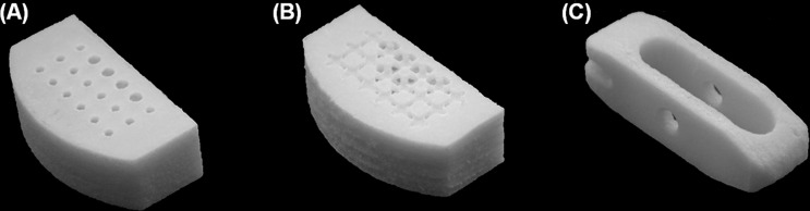
For compression tests, fusion cages with (a) cylindrical pore microstructures, (b) optimized microstructures, and (c) the conventional TLIF cage were fabricated without detailed features to eliminate the initial yield caused by teethlike geometric features
Fig. 6.

Line graph showing compression test results, confirming superior stiffness and strength of the optimized designs over conventional TLIF design
Solid cylinders (8 mm diameter and 16 mm height) were fabricated to determine bulk compressive modulus and yield stress of the sintered PCL/HA mixture (Fig. 7). Young’s modulus was 295.3 ± 13.6 MPa and yield stress was 10.4 ± 0.2 MPa (n = 10).
Fig. 7.

Stress–strain curve obtained from compression test of a bulk cylindrical specimen to determine Young’s modulus and yield stress for the FE analysis
Estimation of Yield From the Stress Analysis.
FE analyses confirmed that porous PCL cages can support physiological loading. To check the load carrying capacity, we first conducted FE analysis on the wall structure. The maximum von Mises stress was 8.23 MPa under 1500 N of compressive force (Fig. 8(a)), which is below the experimentally measured yield stress (10.4 MPa) for sintered bulk PCL/HA specimens. However, introduction of microstructures raised the local stress levels over the yield at the thin structural features (Figs. 8(b) and 8(c)). Based on the compression tests (Table 3), however, yield of the global structure was over 3000 N, indicating the surrounding wall supported the load over local yield load. When assuming initial bony fusion, local stresses at the pores reduced to 9.34 and 8.6 MPa, which are below yield (Figs. 8(d) and 8(e)).
Fig. 8.

(a) von Mises stress level for optimal fusion cage without pore structures is below the yield stress (8.5 MPa). With initial pore structures (b) and (c), the stress level increased over the yield compared to (a). However, after initial bony fusion inside the pores (d and e), the stress level decreased below the yield (9 MPa). These results indicate that the majority of loading support is provided by the outer wall. Although local yield at the microstructures increases initially, ingrown bone will take over the loads from the fusion cage, alleviating the load burden at the microstructures.
Table 3.
Stiffness and yield loads of two designed cages with and without microstructures compared with those of conventional TLIF and poly-L-lactic acid cages [ 49 ]
| Cage | Stiffness (N/mm) | 0.2% yield load (N) |
|---|---|---|
| Cylindrical pore cage | 7117.9 | 3376.2 |
| Optimal pore cage | 7548.6 | 2923.5 |
| Cage wall only | 5228.1 | 1947.4 |
| Conventional TLIF cage | 2455.4 | 1248.5 |
| Poly-L-lactic acid cage | 4000 a | 3500 a |
Average values of stiffness and yield load taken from van Dijk et al. [49].
Discussion
Biodegradable cages have received considerable attention as an interbody fusion system. The underlying rationale is that reduced stiffness adjacent to bone may eliminate stress shielding and that complete resorption of the cage will avoid adverse foreign body reactions. Conventional hollowed cylindrical cages or vertical ring types, however, may not be adequate design candidates for biodegradable cages. The thin-wall geometry originally designed for metallic cages may collapse under physiological loading conditions when simply replacing permanent materials, such as titanium or polyethylethylketone, with significantly less-rigid biodegradable polymers. In this regard, integrated global and local topology optimization in the design of PCL cages has been demonstrated to achieve these generally desired stiffness and strength characteristics needed for better fusion outcomes. Furthermore, this design approach is highly flexible and can be readily applied to either preclinical animal models or human clinical studies.
Global topology optimization can incorporate an anatomically accurate shape, which makes in situ fusion cage design possible. Various physiologically relevant loading modes at the lumbar spine were concurrently considered in the optimization procedure to ensure in vivo structural integrity. Measured compressive strength revealed that our optimally designed PCL cages could support physiological load magnitudes at the lumbar spine. Furthermore, this design technique facilitates the design of fusion cages with specific physiological demands by introducing local microstructures with various stiffness, permeability, and diffusivity properties.
With the solid freeform fabrication technique, our optimal PCL cages could be accurately constructed with controlled pore architectures and sufficient mechanical properties. The effectiveness of a laser-sintered PCL fabrication as a bone scaffold was previously attested by its stiffness, which is close to that of trabecular bone, and anatomically specific global shape with controlled porous architecture to allow bony ingrowth [30]. While the modulus of the bulk PCL specimen was 120 MPa in that study, the experimental and computationally estimated compressive modulus of porous scaffolds ranged from 46 to 68 MPa, falling within the lower range of human trabecular bone [31]. In our study, the compressive modulus of the bulk specimen was 295 MPa, which is in the mid-range of reported values (120 ∼ 450 MPa) [30,32–34]. The improved strength may be due to optimally determined SLS processing parameters, including laser power, beam path speed, and PCL powder particle size.
Our porous fusion cages demonstrated their ability to support physiological loadings. To estimate in vivo load level in different postures, intradiskal pressure was measured in flexion up to 30 deg using a pressure needle, and converted to load by multiplying disk area, which was measured from a magnetic resonance imaging scan [35]. In that study, load levels at L4–L5 lumbar spine have been estimated around 500 N to 3000 N, varying according to posture. In another study, theoretical estimation of axial loads at L3 were reported to range from 340 N ∼ 2350 N [36]. Our compression tests revealed that the optimal fusion cages scaled for human vertebral geometry could withstand over 3 kN of loads, which is above the physiological level of the human lumbar spine. The comparison of compressive mechanical responses with conventional TLIF cages also demonstrated the inadequacy of adapting a design previously used for metallic cages. Moreover, the compliance of PCL may also benefit mechanical stimulus on growing bone, as results from the stress analysis indicated that load transfer took place from the fusion cage to newly generated bone when initial bony fusion was assumed. However, whether the transferred load becomes detrimental over time warrants further study and investigation of mechanoregulation within the microstructure.
The stiffness of our fabricated fusion cage can be improved by increasing the HA content in the PCL powder, owing to HA’s high stiffness factor. Shor et al. [37] demonstrated a 40% increase in the compressive modulus by adding 25% HA. It was also reported that stiffness of the PCL/HA mixture was proportional to the content of HA [32]. The reason we chose 7% HA was due to a limitation in our SLS laser beam controllability. With further optimization of the laser beam parameter, our sintered PCL/HA composite fusion cages may have improved mechanical strength.
In an effort to elucidate optimal scaffold design parameters for better tissue regeneration, pore architectures, such as pore size and porosity, have been extensively investigated. Although there were large variations among researchers regarding optimal pore size, a minimum 300 μm pore size has been suggested to enhance bone growth and capillary formation [38]. The minimum pore size of our optimal cages was approximately 800 μm, which is limited by current SLS processing parameters. In a previous study by our group [39], no significant differences were found in bone growth into PCL scaffolds at longer time points between pore sizes of 350 μm and 800 μm. Thus, it is expected that our porous PCL cages may enhance bone ingrowth with large enough pores, along with the maximized permeability design provided by local topology optimization.
In addition to sufficient compressive modulus for load bearing, irreversible creep of the PCL may play a favorable role in preventing fracture of the cage into small pieces and maintaining structural connectivity, even under excessive loading conditions. PCL has a very low glass transition temperature of −62 °C and melting point of 57 °C. At room temperature or in a body, PCL is in a rubbery state, thus exhibiting high ductility [33]. The long degradation profile compared to other degradable polymers may make PCL more suitable to interbody fusion, which requires a long healing time of more than one year. Fast degradation and loss of structural integrity may cause poor fusion performance. Jiya et al. [40] raised concern of using PLDLLA poly(l,dl- lactic acid) cages in their prospective randomized clinical study comparing fusion performance between polyether ether ketone (PEEK) and PLDLLA cages. Their PLDLLA showed significantly higher subsidence and lower fusion rates compared to PEEK due to early device failure. The authors explained that the rapid decrease in mechanical strength during degradation could be related to device failure, which in turn resulted in the low rate of fusion. In vitro measurements of mechanical properties of PCL, such as modulus and yield stress, were shown to remain unchanged during the entire degradation time course [41]. PCL was also shown to maintain initial elastic modulus and 95% of polymer mass up to 12 months in vivo [42]. However, it should be noted that degradable spine cages are still subject to mechanical failure over time under continuous loading, depending on the magnitude of the load [43].
The validity of using quadrupeds in studies of spine biomechanics has been questioned due to differences in the anatomy and posture of quadrupeds [44]. However, spinal trabecular arrangements were found to be similar between human and porcine vertebrae, indicating axial compression along the spinal axis is dominant in porcine spine, based on Wolf’s law [45]. In addition, facet joints are interlocking, rather than sliding with each other, which indicates that the load perpendicular to the spinal column can be converted to longitudinal stress along the spinal column. Smit [46] also supported the large quadruped pig animal model because of these similar loading modes. The author, however, noted that the considerably higher density of trabecular bone in quadruped vertebral bodies is an indication of higher load levels in the animal lumbar spine. The global topology optimization in our study was conducted with porcine lumbar spine geometry, but the material properties were human. For application in a preclinical study, it will be important to consider the effect of these differences by developing optimal topology designs for both sets of material properties.
One possible application for optimal microstructures in interbody fusion would be controlled release of biologics, such as Bone morphogenetic protein 2 (BMP2). Although the microstructures were optimized in terms of functional properties such as permeability and diffusivity, it should be noted that the optimally designed microstructures were found to have a larger pore surface area than in the cylindrical or spherical pore microstructures (Table 4, Fig. 3). Increased surface area with maximized permeability may increase the efficacy of osteobiologic release, especially if the BMP2 can be tightly bound to the cage with local retention. It is possible to modify the surfaces of these optimized cages using either biomineralization methods [47] or by chemical conjugation techniques [48]. Integration of designed cages with osteobiologic delivery could address the limitations of current cage delivery systems that use a collagen sponge for osteobiologic delivery that is separate from the load-bearing cage.
Table 4.
Surface-to-volume ratio of microstructures
Conclusions
Integrated global-local topology optimization combined with the SFF technique and using a PCL/HA composite is a promising method for the design of biodegradable fusion cages. Based on experimental and computational verification, optimally designed PCL cages have sufficient mechanical properties to support lumbar interbody loads. This, combined with the longer degradation period of PCL, may once again make bioresorbable cages a viable solution for spine fusion applications. However, rigorous preclinical testing of this postulate in a large animal model will be required.
Acknowledgment
The authors gratefully acknowledge funding support for this study by R21 NS055731 from National Institute of Neurological Disorders and Stroke (NINDS)/National Institute of Health (NIH) and R01 AR056649 from National Institute of Arthritis and Musculoskeletal and Skin Diseases (NIAMS)/NIH.
Glossary
Abbreviations
- BMP =
bone morphogenetic protein
- FE =
finite element
- HA =
hydroxyapatite
- PCL =
poly(ε-caprolactone)
- SFF =
solid freeform fabrication
- SLS =
selective laser sintering
- TLIF =
transforaminal lumbar interbody fusion
Contributor Information
Heesuk Kang, Department of Mechanical Engineering, University of Michigan, Ann Arbor, MI 48109;; Department of Biomedical Engineering, University of Michigan, Ann Arbor, MI 48109
Scott J. Hollister, Department of Mechanical Engineering, University of Michigan, Ann Arbor, MI 48109; Department of Biomedical Engineering, University of Michigan, Ann Arbor, MI 48109; Department of Surgery, University of Michigan, Ann Arbor, MI 48109
Frank La Marca, Spine Research Laboratory, Department of Neurosurgery, University of Michigan, Ann Arbor, MI 48109;; Department of Biomedical Engineering, University of Michigan, Ann Arbor, MI 48109
Paul Park, Spine Research Laboratory, Department of Neurosurgery, University of Michigan, Ann Arbor, MI 48109.
Chia-Ying Lin, Spine Research Laboratory, Department of Neurosurgery, University of Michigan, Ann Arbor, MI 48109;; Department of Orthopaedic Surgery, University of Michigan, Ann Arbor, MI 48109; Department of Biomedical Engineering, University of Michigan, Ann Arbor, MI 48109 , e-mail: lincy@umich.edu
References
- [1]. Deyo, R. A. , Gray, D. T. , Kreuter, W. , Mirza, S. , and Martin, B. I. , 2005, “United States Trends in Lumbar Fusion Surgery for Degenerative Conditions,” Spine, 30(12), pp. 1441–1447. 10.1097/01.brs.0000166503.37969.8a [DOI] [PubMed] [Google Scholar]
- [2]. Chen, N. F. , Smith, Z. A. , Stiner, E. , Armin, S. , Sheikh, H. , and Khoo, L. T. , 2010, “Symptomatic Ectopic Bone Formation After Off-Label Use of Recombinant Human Bone Morphogenetic Protein-2 in Transforaminal Lumbar Interbody Fusion,” J. Neurosurg. Spine, 12(1), pp. 40–46. 10.3171/2009.4.SPINE0876 [DOI] [PubMed] [Google Scholar]
- [3]. McAfee, P. C. , 1999, “Interbody Fusion Cages in Reconstructive Operations on the Spine,” J. Bone Joint. Surg. Am., 81(6), pp. 859–880. [DOI] [PubMed] [Google Scholar]
- [4]. Kuslich, S. D. , Ulstrom, C. L. , Griffith, S. L. , Ahern, J. W. , and Dowdle, J. D. , 1998, “The Bagby and Kuslich Method of Lumbar Interbody Fusion. History, Techniques, and 2-Year Follow-Up Results of a United States Prospective, Multicenter Trial,” Spine, 23(11), pp. 1267–1279. 10.1097/00007632-199806010-00019 [DOI] [PubMed] [Google Scholar]
- [5]. Whitecloud, T. S. III , Castro, F. P. Jr. , Brinker, M. R. , Hartzog, C. W. Jr. , Ricciardi, J. E. , and Hill, C. , 1998, “Degenerative Conditions of the Lumbar Spine Treated With Intervertebral Titanium Cages and Posterior Instrumentation for Circumferential Fusion,” J. Spinal Disord., 11(6), pp. 479–486. 10.1097/00002517-199812000-00005 [DOI] [PubMed] [Google Scholar]
- [6]. Kanayama, M. , Cunningham, B. W. , Haggerty, C. J. , Abumi, K. , Kaneda, K. , and McAfee, P. C. , 2000, “In Vitro Biomechanical Investigation of the Stability and Stress-Shielding Effect of Lumbar Interbody Fusion Devices,” J. Neurosurg., 93(2 Suppl.), pp. 259–265. [DOI] [PubMed] [Google Scholar]
- [7]. Smith, K. R. , Hunt, T. R. , Asher, M. A. , Anderson, H. C. , Carson, W. L. , and Robinson, R. G. , 1991, “The Effect of a Stiff Spinal Implant on the Bone-Mineral Content of the Lumbar Spine in Dogs,” J. Bone Joint Surg. Am., 73(1), pp. 115–123. [PubMed] [Google Scholar]
- [8]. van Dijk, M. , Smit, T. H. , Sugihara, S. , Burger, E. H. , and Wuisman, P. I. , 2002, “The Effect of Cage Stiffness on the Rate of Lumbar Interbody Fusion: An in Vivo Model Using Poly(l-Lactic Acid) and Titanium Cages,” Spine, 27(7), pp. 682–688. 10.1097/00007632-200204010-00003 [DOI] [PubMed] [Google Scholar]
- [9]. Cizek, G. R. , and Boyd, L. M. , 2000, “Imaging Pitfalls of Interbody Spinal Implants,” Spine, 25(20), pp. 2633–2636. 10.1097/00007632-200010150-00015 [DOI] [PubMed] [Google Scholar]
- [10]. Robertson, D. D. , Sharma, G. B. , Gilbertson, L. G. , and Kang, J. D. , 2009, “Bone Densitometry Within Titanium Lumbar Interbody Fusion Cages: A Computed Tomography Feasibility Study,” Spine, 34(25), pp. 2792–2796. 10.1097/BRS.0b013e3181b61e00 [DOI] [PubMed] [Google Scholar]
- [11]. van Dijk, M. , Smit, T. H. , Burger, E. H. , and Wuisman, P. I. , 2002, “Bioabsorbable Poly-L-Lactic Acid Cages for Lumbar Interbody Fusion: Three-Year Follow-Up Radiographic, Histologic, and Histomorphometric Analysis in Goats,” Spine, 27(23), pp. 2706–2714. 10.1097/00007632-200212010-00010 [DOI] [PubMed] [Google Scholar]
- [12]. van Dijk, M. , van Diest, P. J. , Smit, T. H. , Berkhof, H. , Burger, E. H. , and Wuisman, P. I. , 2005, “Four-Year Follow-Up of Poly-L-Lactic Acid Cages for Lumbar Interbody Fusion in Goats,” J. Long Term Eff. Med. Implants, 15(2), pp. 125–138. 10.1615/JLongTermEffMedImplants.v15.i2.20 [DOI] [PubMed] [Google Scholar]
- [13]. Smit, T. H. , Krijnen, M. R. , van Dijk, M. , and Wuisman, P. I. , 2006, “Application of Polylactides in Spinal Cages: Studies in a Goat Model,” J. Mater. Sci. Mater. Med., 17(12), pp. 1237–1244. 10.1007/s10856-006-0597-5 [DOI] [PubMed] [Google Scholar]
- [14]. Kandziora, F. , Pflugmacher, R. , Scholz, M. , Eindorf, T. , Schnake, K. J. , and Haas, N. P. , 2004, “Bioabsorbable Interbody Cages in a Sheep Cervical Spine Fusion Model,” Spine, 29(17), pp. 1845–1856. 10.1097/01.brs.0000137060.79732.78 [DOI] [PubMed] [Google Scholar]
- [15]. Weiner, B. K. , and Fraser, R. D. , 1998, “Spine Update Lumbar Interbody Cages,” Spine, 23(5), pp. 634–640. 10.1097/00007632-199803010-00020 [DOI] [PubMed] [Google Scholar]
- [16]. Hollister, S. J. , 2005, “Porous Scaffold Design for Tissue Engineering,” Nat. Mater., 4(7), pp. 518–524. 10.1038/nmat1421 [DOI] [PubMed] [Google Scholar]
- [17]. Lin, C. Y. , Hsiao, C. C. , Chen, P. Q. , and Hollister, S. J. , 2004, “Interbody Fusion Cage Design Using Integrated Global Layout and Local Microstructure Topology Optimization,” Spine, 29(16), pp. 1747–1754. 10.1097/01.BRS.0000134573.14150.1A [DOI] [PubMed] [Google Scholar]
- [18]. Lin, C. Y. , Wirtz, T. , La Marca, F. , and Hollister, S. J. , 2007, “Structural and Mechanical Evaluations of a Topology Optimized Titanium Interbody Fusion Cage Fabricated by Selective Laser Melting Process,” J. Biomed. Mater. Res. A, 83(2), pp. 272–279. [DOI] [PubMed] [Google Scholar]
- [19]. Hollister, S. J. , Maddox, R. D. , and Taboas, J. M. , 2002, “Optimal Design and Fabrication of Scaffolds to Mimic Tissue Properties and Satisfy Biological Constraints,” Biomaterials, 23(20), pp. 4095–4103. 10.1016/S0142-9612(02)00148-5 [DOI] [PubMed] [Google Scholar]
- [20]. Hollister, S. J. , Levy, R. A. , Chu, T. M. , Halloran, J. W. , and Feinberg, S. E. , 2000, “An Image-Based Approach for Designing and Manufacturing Craniofacial Scaffolds,” Int. J. Oral Maxillofac. Surg., 29(1), pp. 67–71. 10.1034/j.1399-0020.2000.290115.x [DOI] [PubMed] [Google Scholar]
- [21]. Hutmacher, D. W. , 2001, “Scaffold Design and Fabrication Technologies for Engineering Tissues–State of the Art and Future Perspectives,” J. Biomater. Sci. Polym. Ed., 12(1), pp. 107–124. 10.1163/156856201744489 [DOI] [PubMed] [Google Scholar]
- [22]. Lin, C. Y. , Schek, R. M. , Mistry, A. S. , Shi, X. , Mikos, A. G. , Krebsbach, P. H. , and Hollister, S. J. , 2005, “Functional Bone Engineering Using Ex Vivo Gene Therapy and Topology-Optimized, Biodegradable Polymer Composite Scaffolds,” Tissue Eng., 11(9–10), pp. 1589–1598. 10.1089/ten.2005.11.1589 [DOI] [PubMed] [Google Scholar]
- [23]. Schek, R. M. , Taboas, J. M. , Hollister, S. J. , and Krebsbach, P. H. , 2005, “Tissue Engineering Osteochondral Implants for Temporomandibular Joint Repair,” Orthod. Craniofac. Res., 8(4), pp. 313–319. 10.1111/j.1601-6343.2005.00354.x [DOI] [PubMed] [Google Scholar]
- [24]. Shiraziadl, A. , Ahmed, A. M. , and Shrivastava, S. C. , 1986, “A Finite-Element Study of a Lumbar Motion Segment Subjected to Pure Sagittal Plane Moments,” J. Biomech., 19(4), pp. 331–350. 10.1016/0021-9290(86)90009-6 [DOI] [PubMed] [Google Scholar]
- [25]. Zhong, Z. C. , Wei, S. H. , Wang, J. P. , Feng, C. K. , Chen, C. S. , and Yu, C. H. , 2006, “Finite Element Analysis of the Lumbar Spine With a New Cage Using a Topology Optimization Method,” Med. Eng. Phys., 28(1), pp. 90–98. 10.1016/j.medengphy.2005.03.007 [DOI] [PubMed] [Google Scholar]
- [26]. Ekstrom, L. , Holm, S. , Holm, A. K. , and Hansson, T. , 2004, “In Vivo Porcine Intradiscal Pressure as a Function of External Loading,” J. Spinal Disord. Tech., 17(4), pp. 312–316. 10.1097/01.bsd.0000092068.78152.00 [DOI] [PubMed] [Google Scholar]
- [27]. Kang, H. , Lin, C.-Y. , and Hollister, S. J. , 2010, “Topology Optimization of Three Dimensional Tissue Engineering Scaffold Architectures for Prescribed Bulk Modulus and Diffusivity,” Struct. Multidisc Optim., 42, pp. 633–644. 10.1007/s00158-010-0508-8 [DOI] [PMC free article] [PubMed] [Google Scholar]
- [28]. Gibiansky, L. V. , and Torquato, S. , 1996, “Connection Between the Conductivity and Bulk Modulus of Isotropic Composite Materials,” Proc. R. Soc. Lond. A, 452(1945), pp. 253–283. 10.1098/rspa.1996.0015 [DOI] [Google Scholar]
- [29]. Nachemson, A. , 1966, “The Load on Lumbar Disks in Different Positions of the Body,” Clin. Orthop. Relat. Res., 45, pp. 107–122. 10.1097/00003086-196600450-00014 [DOI] [PubMed] [Google Scholar]
- [30]. Williams, J. M. , Adewunmi, A. , Schek, R. M. , Flanagan, C. L. , Krebsbach, P. H. , Feinberg, S. E. , Hollister, S. J. , and Das, S. , 2005, “Bone Tissue Engineering Using Polycaprolactone Scaffolds Fabricated Via Selective Laser Sintering,” Biomaterials, 26(23), pp. 4817–4827. 10.1016/j.biomaterials.2004.11.057 [DOI] [PubMed] [Google Scholar]
- [31]. Goulet, R. W. , Goldstein, S. A. , Ciarelli, M. J. , Kuhn, J. L. , Brown, M. B. , and Feldkamp, L. A. , 1994, “The Relationship Between the Structural and Orthogonal Compressive Properties of Trabecular Bone,” J. Biomech., 27(4), pp. 375–389. 10.1016/0021-9290(94)90014-0 [DOI] [PubMed] [Google Scholar]
- [32]. Ang, K. C. , Leong, K. F. , Chua, C. K. , and Chandrasekaran, M. , 2007, “Compressive Properties and Degradability of Poly(Epsilon-Caprolactone)/Hydroxyapatite Composites Under Accelerated Hydrolytic Degradation,” J. Biomed. Mater. Res. Part A, 80A(3), pp. 655–660. 10.1002/jbm.a.30996 [DOI] [PubMed] [Google Scholar]
- [33]. Engelberg, I. , and Kohn, J. , 1991, “Physico-Mechanical Properties of Degradable Polymers Used in Medical Applications: A Comparative Study,” Biomaterials, 12(3), pp. 292–304. 10.1016/0142-9612(91)90037-B [DOI] [PubMed] [Google Scholar]
- [34]. Eshraghi, S. , and Das, S. , 2010, “Mechanical and Microstructural Properties of Polycaprolactone Scaffolds With One-Dimensional, Two-Dimensional, and Three-Dimensional Orthogonally Oriented Porous Architectures Produced by Selective Laser Sintering,” Acta Biomater., 6(7), pp. 2467–2476. 10.1016/j.actbio.2010.02.002 [DOI] [PMC free article] [PubMed] [Google Scholar]
- [35]. Takahashi, I. , Kikuchi, S. , Sato, K. , and Sato, N. , 2006, “Mechanical Load of the Lumbar Spine During Forward Bending Motion of the Trunk-a Biomechanical Study,” Spine, 31(1), pp. 18–23. 10.1097/01.brs.0000192636.69129.fb [DOI] [PubMed] [Google Scholar]
- [36]. Schultz, A. , Andersson, G. , Ortengren, R. , Haderspeck, K. , and Nachemson, A. , 1982, “Loads on the Lumbar Spine. Validation of a Biomechanical Analysis by Measurements of Intradiscal Pressures and Myoelectric Signals,” J. Bone Joint Surg. Am., 64(5), pp. 713–720. [PubMed] [Google Scholar]
- [37]. Shor, L. , Gueceri, S. , Gandhi, M. , Wen, X. , and Sun, W. , 2008, “Solid Freeform Fabrication of Polycaprolactone/Hydroxyapatite Tissue Scaffolds,” ASME J. Manuf. Sci. E.-T., 130(2), p. 021018. 10.1115/1.2898411 [DOI] [Google Scholar]
- [38]. Karageorgiou, V. , and Kaplan, D. , 2005, “Porosity of 3D Biomaterial Scaffolds and Osteogenesis,” Biomaterials, 26(27), pp. 5474–5491. 10.1016/j.biomaterials.2005.02.002 [DOI] [PubMed] [Google Scholar]
- [39]. Roosa, S. M. , Kemppainen, J. M. , Moffitt, E. N. , Krebsbach, P. H. , and Hollister, S. J. , 2010, “The Pore Size of Polycaprolactone Scaffolds Has Limited Influence on Bone Regeneration in an in Vivo Model,” J. Biomed. Mater. Res. A, 92(1), pp. 359–368. [DOI] [PubMed] [Google Scholar]
- [40]. Jiya, T. , Smit, T. , Deddens, J. , and Mullender, M. , 1976, “Posterior Lumbar Interbody Fusion Using Nonresorbable Poly-Ether-Ether-Ketone Versus Resorbable Poly-L-Lactide-Co-D,L-Lactide Fusion Devices: A Prospective, Randomized Study to Assess Fusion and Clinical Outcome,” Spine, 34(3), pp. 233–237. 10.1097/BRS.0b013e318194ed00 [DOI] [PubMed] [Google Scholar]
- [41]. Karjalainen, T. , Hiljanen-Vainio, M. , Malin, M. , and Seppala, J. , 1996, “Biodegradable Lactone Copolymers. III. Mechanical Properties of Epsilon-Caprolactone and Lactide Copolymers After Hydrolysis in Vitro,” J. Appl. Polym. Sci., 26(11), pp. 3779–3787. [Google Scholar]
- [42]. Pitt, C. G. , Chasalow, F. I. , Hibionada, Y. M. , Klimas, D. M. , and Schindler, A. , 1981, “Aliphatic Polyesters. I. The Degradation of Poly(Epsilon-Caprolactone) in Vivo,” J. Appl. Polym. Sci., 26(11), pp. 3779–3787. 10.1002/app.1981.070261124 [DOI] [Google Scholar]
- [43]. Smit, T. H. , Engels, T. A. , Wuisman, P. I. , and Govaert, L. E. , 1976, “Time-Dependent Mechanical Strength of 70/30 Poly(L, DL-Lactide): Shedding Light on the Premature Failure of Degradable Spinal Cages,” Spine, 33(1), pp. 14–18. 10.1097/BRS.0b013e31815e39df [DOI] [PubMed] [Google Scholar]
- [44]. Goel, V. K. , and Gilbertson, L. G. , 1997, “Basic Science of Spinal Instrumentation,” Clin. Orthop. Relat. Res., 335, pp. 10–31. [PubMed] [Google Scholar]
- [45]. Lin, R. M. , Tsai, K. H. , and Chang, G. L. , 1997, “Distribution and Regional Strength of Trabecular Bone in the Porcine Lumbar Spine,” Clin. Biomech., 12(5), pp. 331–336. 10.1016/S0268-0033(97)00012-0 [DOI] [PubMed] [Google Scholar]
- [46]. Smit, T. H. , 2002, “The Use of a Quadruped as an in Vivo Model for the Study of the Spine—Biomechanical Considerations,” Eur. Spine J., 11(2), pp. 137–144. 10.1007/s005860100346 [DOI] [PMC free article] [PubMed] [Google Scholar]
- [47]. Murphy, W. L. , Kohn, D. H. , and Mooney, D. J. , 2000, “Growth of Continuous Bonelike Mineral Within Porous Poly(Lactide-Co-Glycolide) Scaffolds in Vitro,” J. Biomed. Mater. Res., 50(1), pp. 50–58. [DOI] [PubMed] [Google Scholar]
- [48]. Zhang, H. , Migneco, F. , Lin, C.-Y. , and Hollister, S. J. , 2010, “Chemically-Conjugated Bone Morphogenetic Protein-2 on Three-Dimensional Polycaprolactone Scaffolds Stimulates Osteogenic Activity in Bone Marrow Stromal Cells,” Tissue Eng. Part A, 16, pp. 3441–3448. 10.1089/ten.tea.2010.0132 [DOI] [PMC free article] [PubMed] [Google Scholar]
- [49]. van Dijk, M. , Smit, T. H. , Arnoe, M. F. , Burger, E. H. , and Wuisman, P. I. , 2003, “The Use of Poly-L-Lactic Acid in Lumbar Interbody Cages: Design and Biomechanical Evaluation in Vitro,” Eur. Spine J., 12(1), pp. 34–40. [DOI] [PubMed] [Google Scholar]