

Significance
Aquaporin channels are able to selectively conduct water across cell membranes, with remarkable efficiency. Although molecular details are crucial to the pore performance, permeability is also strongly limited by viscous dissipation at the entrances. Could the hourglass shape of aquaporins optimize such entrance effects? We show that conical entrances with suitable opening angle can indeed provide a large increase of the channel permeability. Strikingly, the optimal opening angles compare well with the angles measured in a large variety of aquaporins, suggesting that their hourglass shape could be the result of a natural selection process toward optimal permeability. This work also provides guidelines to optimize the performances of artificial nanopores, with applications in desalination, ultrafiltration, or energy conversion.
Keywords: nanofluidics, hydrodynamic permeability, biochannels
Abstract
The ubiquitous aquaporin channels are able to conduct water across cell membranes, combining the seemingly antagonist functions of a very high selectivity with a remarkable permeability. Whereas molecular details are obvious keys to perform these tasks, the overall efficiency of transport in such nanopores is also strongly limited by viscous dissipation arising at the connection between the nanoconstriction and the nearby bulk reservoirs. In this contribution, we focus on these so-called entrance effects and specifically examine whether the characteristic hourglass shape of aquaporins may arise from a geometrical optimum for such hydrodynamic dissipation. Using a combination of finite-element calculations and analytical modeling, we show that conical entrances with suitable opening angle can indeed provide a large increase of the overall channel permeability. Moreover, the optimal opening angles that maximize the permeability are found to compare well with the angles measured in a large variety of aquaporins. This suggests that the hourglass shape of aquaporins could be the result of a natural selection process toward optimal hydrodynamic transport. Finally, in a biomimetic perspective, these results provide guidelines to design artificial nanopores with optimal performances.
Aquaporins (AQPs) are water-selective channels, ubiquitous in the living world (1, 2). They are involved in many physiological processes and play a crucial role in water exchanges across membranes, in particular under osmotic gradients. AQPs are considered to be excellent water filters, able to achieve contradictory and exquisite tasks: they exhibit high water permeability while ensuring excellent water selectivity (3, 4). From a technological point of view, designing artificial systems with similar performances would make a breakthrough with applications in water desalination, ultrafiltration, or energy harvesting based on osmotic power. By overcoming the limits of macroscopic transport, novel nanofluidic systems––involving transport of fluids in specifically designed nanochannels––have recently raised great hopes toward the realization of such achievements (5, 6). One may quote in particular experiments reporting high flow rate of water through carbon nanotube membranes (7, 8), as well as giant osmotic effects in boron nitride nanotubes (9).
However, to design artificial nanopores with optimized performances, it would be interesting to investigate more closely the solution reached by biological nanochannels to perform similar functionalities. An intriguing aspect of AQPs, highlighted in Fig. 1, is the hourglass shape exhibited by the aqueous pathway, with the inner part of the pore connected to the bulk water reservoirs via cone-shaped vestibules. The central pore is of molecular size, and water is transported in this region as a single file (5). Selectivity is achieved in this molecular scale confinement via a subtle molecular organization of the confining pore (3, 4, 10–13). On the other hand, the conical entrances are of much larger size, making a slow transition toward the bulk water. Whereas the inner part of the pore is ruled by one-dimensional molecular transport (14), continuum hydrodynamics should apply to some extent in these cone-shaped vestibules, as it was shown that the Navier–Stokes equation remains valid down to extremely small length scales (typically 1 nm for water) (6, 15). In this simplifying picture, the central part is the key to ensure the selectivity at the molecular scale, but the overall transport efficiency nonetheless incorporates a priori effects occurring in the conical entrances that make the transition to the bulk.
Fig. 1.

(A) Molecular structure of human aquaporin 4 (hAQP4) obtained from the Protein Data Bank (28). (B) Profiles of two aquaporins collected from ref. 13. Pore dimensions were estimated using the HOLE program (29). (C) Biconical channel considered in this work. The central cylinder, where perfect slip is assumed, is connected to two truncated cones of length L, opening angle α, and with perfect or finite slip (slip length b; see text). (D) Schematic of the system used for the FE resolution of the Stokes equation (COMSOL). The channel is connected to half-spherical reservoirs (not to scale). Color represents the magnitude of fluid velocity, from blue (slow flow) to red (fast flow).
Accordingly, we raise in this paper the question of hydrodynamic entrance effects. Specifically, we study whether the hourglass shape of AQPs corresponds to an optimum with respect to hydrodynamic dissipation. As we demonstrate below, the hourglass geometry does indeed display an optimal angle for which entrance effects are minimized, and the resulting gain in overall channel permeability can reach hundreds of percent. Strikingly, geometrical parameters measured on a variety of AQPs are found to compare well with these optimal opening angles. In a broader biomimetic perspective, our findings point to general design rules to minimize entrance effects and ensure optimal transport in artificial nanopores.
Hydrodynamic Entrance Effects
The question of entrance effects in hydrodynamic flows goes back to the early history of hydrodynamics. In 1891, Sampson obtained the exact solution for the Stokes flow through a circular aperture in an infinitely thin membrane (16) and found that the pressure drop Δp across the membrane was
 |
with a the aperture radius, η the liquid dynamic viscosity, and Q the flow rate through the aperture. The pressure drop results from the narrowing of the streamlines over a range a. The scaling results accordingly from Stokes’ equation:  , with
  the typical fluid velocity. Extending this estimate to the converging flow into a cylindrical pore, the previous Sampson’s formula provides a very good estimate of the access pressure drop (17), as highlighted by an exact calculation (18).
Now, if one considers water transport through a pore, the dissipation occurring in the bulk access regions yields an upper bound to the hydrodynamic permeability. In nanochannels where inner dissipation is extremely small (such as carbon nanotubes, refs. 7, 8, 19, 20), entrance effects thus act as the limiting factor for water transport, as shown recently (21–23), and exemplified by the capillary uptake of water in carbon nanotubes (24). For AQPs, whose dissipation in the inner part has not been fully characterized, a simple estimate nevertheless shows that entrance effects contribute in large part to the global hydrodynamic resistance. Indeed, the permeabilities of AQPs reported in the literature vary typically in the range  to
to  (25). This is to be compared with a typical order of magnitude for the entrance contribution to the permeability, which can be estimated from Sampson’s formula,*
Eq 1, giving
(25). This is to be compared with a typical order of magnitude for the entrance contribution to the permeability, which can be estimated from Sampson’s formula,*
Eq 1, giving  .† This estimate shows that entrance effects contribute importantly to the overall AQP permeability and cannot be overlooked. It is therefore interesting to investigate whether––regardless of the dissipation occurring in the central, molecular part of the pore––strategies exist to reduce significantly these entrance effects. Altogether, the global permeability of a pore may be written as two resistances in series,
where the two contributions on the right-hand side stand for the two access resistances and the resistance originating in the central part of the channel. In the following we focus on the first access part of the permeability, so that our result constitute an upper bound to the total permeability. We show that a conical shape allows one to reduce considerably the corresponding entrance dissipation, and thus provides an optimal shape for water transport.
Optimized Permeability of Hourglass-Shaped Pores
Inspired by the AQP shape (Fig. 1), we investigate hydrodynamic entrance effects in nanopores with an hourglass shape. We consider a pore made of a central cylinder with radius a and length H, connected to two conical vestibules, with length L and opening angle α (Fig. 1C). This system will be studied at the level of the continuum Stokes equation. Given that AQP dimensions are subnanometric, with the pore mouth in the nanometer range down to a central pore diameter ∼0.3 nm, using continuum hydrodynamics may certainly be questioned. However, it is known that the Navier–Stokes equation is remarkably robust, remaining valid down to the nanometer scale (6, 15), so that it should apply––at least to some extent––in the entrance regions connecting the pore mouth to the bulk.*
Now, fluid transport inside the central part of the AQP belongs to the single-file regime and the physics at play here cannot be captured by a continuum description. However, we are not interested here in the specific selectivity of the AQP, which would indeed require a detailed atomic modeling (10–13). To focus on entrance effects alone, we consider a simplified view in which all dissipation in the AQP central channel is neglected. This is done by assuming a perfect-slip boundary condition on the pore surface (Materials and Methods), so that surface friction is vanishing in this central part. By doing so, we thus focus on the entrance contribution to the permeability, i.e., the first term in Eq. 2. Therefore, our results provide an upper bound to the total permeability of the pore.
Boundary conditions (BC) in the conical regions have also to be prescribed (Materials and Methods). As shown to be relevant for nanoscale flows (30), we assume a partial slip BC on the cones’ walls, with the velocity field at the surface obeying  , where b is the so-called “slip length” and vt is the tangential component of the velocity. Interestingly, the molecular structure of the AQP in contact with water is mostly hydrophobic (3–5) (with hydrophilic patches to ensure that water penetrates through the pore), and in line with recent work on hydrodynamic slippage (6, 30), a slip length in the range of tens of nanometers may typically be expected. This value is large compared with the other typical length scale of the nanopore,
  . Consequently, we will start our discussion by assuming perfect-slip BC (b = ∞), and then relax this condition in a second step. The Stokes equation with the above BC is solved numerically (Materials and Methods). We will also present a simple model mimicking the generic aspects of flow in the access regions of AQPs, which is able to provide the main features of hydrodynamic entrance effects.
Our main result is illustrated in Fig. 2, which shows the hydrodynamic permeability K of the hourglass channel as a function of the opening angle α. The permeability  provides the flow rate Q for a given pressure drop Δp. As highlighted in this figure, for any cone length L, the permeability is a nonmonotonic function of the opening angle of the pore: starting from the cylinder geometry (α = 0), the permeability starts by increasing very quickly with α, before decreasing slowly for larger angles. There is accordingly an optimal angle αopt which maximizes the channel permeability, i.e., yields a maximal flow rate under a given pressure forcing. Compared with the cylindrical case (α = 0), the optimal geometry (α = αopt) yields a very significant increase in permeability, especially for long cones. At L/a = 20 for instance, the optimal permeability is 6 times larger than the one of a cylinder. Although it increases for shorter cones, the optimal angle remains small, below 10° for L/a > 5. Surprisingly, a tiny departure from the straight cylinder makes for a large effect on entrance dissipation. This is an unexpected result and, to gain insight into its origins, we now develop a simplified model to rationalize viscous dissipation in the hourglass channel.
Fig. 2.

Hydrodynamic permeability K = Q/Δp of the hourglass nanochannel as a function of the opening angle α, obtained from FE calculations. K is normalized by K0 = K(α = 0). Perfect slip (b = ∞) is assumed on the cones’ inner walls. Each curve corresponds to a cone length L.
Toward a Simplified Analytical Model
So far, we assumed in a first step a negligible friction on the cone’s surface (perfect slip). In this situation, the dissipation is expected to occur mostly within the two transition regions: from the reservoir to the cone (first entrance), and from the cone to the cylinder (second entrance). This is confirmed by the numerical results, as highlighted in Fig. 3, where we have plotted the local viscous dissipation rate  , with
  the strain rate tensor. The spatial extent of both regions is given by the local radius, with a prefactor close to unity. This figure shows that increasing the opening angle shifts the dissipation from the first entrance to the second. This is to be expected if one realizes that the streamlines basically have to follow the surface of the pore, and that the second angle between the cone and the cylinder increases as the first angle between the wall and the cone decreases (the sum of the two angles being constant due to geometry).
Fig. 3.

Local viscous dissipation rate D (see text) inside the nanochannel for different values of the angle α. The color scale, from blue to red, indicates increasing values of local viscous dissipation. Perfect-slip BC is imposed on the cone walls. From A to D, α = 0, 5, 10, and 25°.
This picture suggests describing the total hydrodynamic resistance of the pore,  (the inverse permeability), as the sum of the various contributions (channel entrance, cone region, and cylinder entrance) in series, as for a resistive circuit:
(Note that the three resistances do not identify with dissipation inside the volume of reservoir, cone, and cylinder, respectively. For example, the entrance resistance includes dissipation taking place both in the reservoir and in the cone.) For such a decomposition to hold, both the cylinder radius a and the entrance radius a′ = a + L tan α should remain small compared with L, which is valid for large  ratio and small opening angle α.
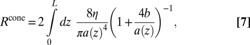
In a cone of infinite extent with arbitrary opening angle and perfect slip at the wall, the Stokes flow is purely radial with a velocity that decreases as 1/r2, where r is the distance from the apex. One may then verify that the pressure drop, evaluated from  , vanishes in this situation. Accordingly, for the case b = ∞ that we consider so far, Rcone is thus negligible, in agreement with numerical results (Fig. 3).
Now, to proceed further and estimate the remaining contributions in Eq. 3, we need to estimate entrance hydrodynamic resistance for two configurations: (i) a conical aperture with a finite angle and perfect slip; (ii) a cone-to-cylinder entrance. These are generalized Sampson geometries, which we consider now.
Generalized Sampson Formula (i): Aperture with Perfect Slip.
To evaluate Rent, we build on previous works. We neglect the effect of the conical shape of the aperture and evaluate Rent for the geometry of a flow entering into a cylinder, an approximation valid for long cones with small angle. As quoted above, Sampson calculation was generalized by Dagan et al. to such geometry (18). However, these calculations assumed a no-slip BC at the pore walls and we need first to generalize this result to perfect slip as considered here. On dimensional grounds, the access resistance of the finite tube is expected to write as  , where C is a numerical prefactor (C = 3 in Sampson expression, Eq. 1). We have computed numerically this prefactor C using finite-element (FE) calculations for a perfectly slipping cylinder of finite length (Fig. 4A). For very short tubes, the BC at the inner wall becomes irrelevant, and Sampson’s result for the infinitely thin membrane is recovered with C = 3. As the tube gets longer, however, the C coefficient increases up to a plateau value of C∞ ∼ 3.75, implying that switching from no slip to perfect slip inside the tube yields a 25% increase in the access resistance. Although counterintuitive at first sight, this behavior can be qualitatively understood by examining the flow profile at the channel end. In the no-slip case (Fig. 4B), this “entry” flow profile is, to a very good approximation, halfway between the parabolic profile of Poiseuille flow and the elliptic profile found in Sampson’s solution (18). As a result, the transition to a plain parabolic profile inside the channel involves only a small dissipation. Because the velocity must vanish at the corner, the entry profile in the perfect-slip tube is quite similar to the no-slip case, suggesting a comparable amount of viscous losses outside the tube. Now, inside a tube with perfect slip at the boundaries, the transition to a plug profile requires significant reorganization of the streamlines (Fig. 4C), resulting in a higher dissipation, hence a higher C. As a side remark, we find that the BC on the external wall has a negligible impact on the access resistance, presumably because any slip that could happen there is strongly hampered by the vanishing velocity at the corner. Coming back to the case of the hourglass-shaped pore, we now estimate the hydrodynamic resistance of the first entrance as
 |
Fig. 4.

(A)  (see text) as a function of the pore length h for a perfectly slipping cylindrical channel, obtained with FE calculations (points). The red line is a guide for the eyes. (Inset) Velocity field in the considered channel. Color represents the amplitude of the fluid velocity, from blue (slow flow) to red (fast flow). (B and C) Schematic profiles of axial velocity in a channel with no slip (NS) and perfect-slip (PS) BC. From left to right: outside far field, entry profile and inside far field.
Generalized Sampson Formula (ii): Cone-to-Cylinder Entrance.
We then investigated the Stokes flow at the junction between a cone and a cylinder, both with perfect slip. We could not obtain an analytical solution for this geometry, but numerical calculations (Materials and Methods) suggest that the hydrodynamic resistance at a cone-to-cylinder transition can be well approximated by
again with C∞ = 3.75. This behavior can be rationalized on the basis of the following “back-of-the-envelope” argument. Far from the junction, streamlines are parallel in the cylinder and radially divergent in the cone. Dissipation occurs only in the vicinity of the junction, where the streamlines change direction by an angle α, so that  . The pressure drop Δp is then given roughly as
 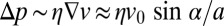 , pointing to the origin of the sin α-dependence for Rent,cyl. Now in the case
  , one should recover the resistance Rent with prefactor C∞, leading to Eq. 5.
Total Hydrodynamic Resistance.
Collecting Eqs. 3–5, and remembering that Rcone ∼ 0, yields the total resistance of the hourglass channel in our simplified model:
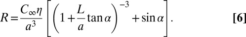 |
This relation exhibits a nonmonotonous behavior versus the angle α, as shown in Fig. 5: the first term on the right-hand side decreases rapidly with α, whereas the second term steadily increases. Physically, these two terms account for dissipation at the first and second entrance, respectively, and their variations confirm the qualitative picture illustrated in Fig. 3. A minimum for the resistance––thus a maximum for the permeability K = R−1––is then found. In particular, for long cones and small angles, 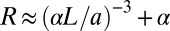 , and the optimal angle decreases with the cone length as
 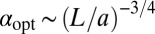 . More quantitatively, Fig. 5 compares FE calculations and the predictions of our simplified model. Whereas a quantitative agreement is not expected in view of the simplifying assumptions underlying our model, the latter is found to capture the optimization phenomenon. In particular, the variation of the optimal angle αopt versus length L/a is well reproduced (Fig. 5, Inset).
Fig. 5.

Pore resistance R versus cone angle α for perfect slip in the cones: comparison between FE calculations (symbols) and Eq. 6 (lines). Results are presented for two pore lengths: L/a = 20 (circles and dashed line) and L/a = 5 (squares and solid line). (Inset) Optimal angle αopt, for which the resistance is minimized, as a function of cone length.
To summarize, there is an optimal angle which maximizes the permeability of an hourglass channel, and minimizes viscous losses. This optimal angle takes rather small values, in the range αopt ∼ 5−20° depending on the length of the conical vestibules, but can lead to very strong improvements in the permeability. Following Dagan et al., it should be possible to calculate the exact solution for a flow inside a biconical nanochannel (18). We leave this ambitious work for future dedicated investigations. However, an approximate model is presented in SI Text.
Extension to Finite Friction on the Cone Surface.
Up to now, we assumed a perfect slip BC at the cones’ surfaces, corresponding to the limit of large slip lengths compared with transverse dimensions b/a → ∞. We now relax this assumption and consider finite b/a. Fig. 6 reports the results of numerical calculations for the hydrodynamic resistance versus opening angle, for various slip lengths b at the cone surface and a fixed cone length, L = 20 a (Materials and Methods). As shown in this figure, an optimal angle minimizing the hydrodynamic resistance is still found for finite slip, and its value increases with decreasing slip length; see also Fig. 7A.
Fig. 6.

Pore resistance R versus opening angle α, for various slip lengths b in the conical regions: comparison between FE calculations (symbols) and analytical expression (lines); see text for detail. The cone length is fixed to L/a = 20.
Fig. 7.

(A) Optimal angle as a function of cone length L for various slip lengths (from top to bottom, b/a = 1, 2, 5, 10, 20): FE results (circles) and model (lines). (B) Angle α evaluated in six aquaporins (Materials and Methods). The gray shaded area corresponds to model predictions for b/a = 1–5. Data are extracted from refs. 13 and 31–36.
Again a simplified model can be built. Although we do not expect entrance effects to be radically modified, a supplementary dissipation will now occur due to finite slippage at the cone surface. This contribution, Rcone in Eq. 3, can be calculated within lubrication theory, valid for small angles α, as
 |
with  the local radius of the cone. Accordingly, an analytical expression for Rcone can be obtained, but its cumbersome expression is not particularly illuminating and we do not report it here. Gathering all contributions in Eq. 3 leads to an analytical expression for the hydrodynamic resistance of the hourglass pore with finite slip length b on the cones. This expression is compared with the numerical calculations in Figs. 6 and 7A. A good agreement is found and the approximate expression is able to capture both the dependency of Rcone with α and b, as well as the order of magnitude of the optimal angle and its variation with b and L/a.
Discussion
Altogether, our results show that the hourglass geometry, associated with small surface friction, does optimize the permeability by reducing considerably the magnitude of entrance effects. A small opening angle in the range 5–20°, depending on the precise geometry and BCs, can increase the permeability by a large factor, reaching hundreds of percent for typical parameters.
Finally, we discuss the relevance of these effects for the shape and the hydrodynamic permeability of AQP. As explained in the introduction, AQPs have hourglass shapes resembling the model geometry considered here. Furthermore, due to their mostly hydrophobic inner surface, a small friction and large slip length is expected at the cone walls. Overall, they exhibit the main ingredients associated with permeability optimization discussed above. To push the comparison further, we have extracted some generic shape parameters of a large variety of AQPs. As illustrated in Fig. 1, and detailed in Materials and Methods, we used molecular structures obtained from high-precision X-ray crystallography—which are available for several AQPs—and obtained the radius profile of the channel, as estimated by the HOLE program (29). Although irregular, those profiles can be divided into three parts: a central (molecular) constriction, and two vestibules with roughly conical shapes. Although matching an atomically detailed structure to a simplified geometry involves a certain degree of arbitrariness (Materials and Methods), we estimated the L and α-parameters of our model for a series of six AQPs. The results for the opening angle α of the AQP conical section are displayed in Fig. 7B. Two conclusions can be drawn from this figure: (i) the opening angle keeps rather low values, within the range 10–25°; (ii) the angle decreases as the cone gets longer. It is therefore striking that the adopted global geometry follows the expectations for the hydrodynamic optimization process discussed above to minimize the entrance permeability.
Obviously, some more detailed features of the AQP geometry cannot be discussed within the previous results. In particular, the structure and shape selection of AQPs follows from a number of constraints and requirements, many of them from the molecular level and the subtle balances to achieve selectivity and efficient transport in the inner single-file constriction. For instance, AQP channels are not symmetric with respect to the membrane half-plane, as the cone toward the cell exterior is apparently longer and more divergent than the interior cone. Within our model, this could be explained only if the inner and outer cylinders radii were different. Although this is often the case, we have considered only the average radius of the central portion, so as to keep a small number of parameters.
Conclusion
The aim of this work was to determine the effect of geometry and BCs on hydrodynamic entrance effects in biconical nanochannels. Using FE calculations, we have shown that compared with a plain cylindrical pipe, a biconical channel of optimal angle can provide a spectacular increase in hydrodynamic permeability. A simplified model based on entrance effects and lubrication approximation rationalizes the observed behavior. Although speculative, this could indicate that the hourglass geometry of AQPs results from a shape optimization, to reduce end effects and maximize water permeability.
Among transmembrane proteins, and ionic channels in particular, examples abound where the particular function––ion selectivity, for instance––is tied to a specific feature of the molecular architecture. However, it remains worth wondering, as we have done here, whether generic factors such as viscous dissipation could be the driving force behind the shapes fine-tuned by evolution. Finally, in a more general biomimetic perspective, this work provides guidelines to optimize the performances of artificial nanopores. Hydrodynamic permeability is indeed a crucial property for applications in water desalination, ultrafiltration, or energy harvesting from salinity gradients. For those particularly relevant nanochannels whose inner dissipation is extremely low (19, 20), it is of prime importance to reduce entrance effects, because they control the overall permeability of the membrane.
Materials and Methods
Numerical Calculations.
We study low Reynolds number flows in 2D axisymmetric geometry. The system of interest includes two reservoirs separated by a membrane containing one biconical nanochannel. We used FE method (COMSOL) to solve the Stokes equation
where v is the fluid velocity, p the pressure, and η the fluid viscosity. We imposed a flow rate Q through the channel and measured the pressure drop across the membrane. To avoid finite size effects, we chose a reservoir much larger than the pore radius. In this study we have imposed the following hydrodynamic boundary conditions:
-
•
No-slip BC: This BC supposes that the fluid has zero velocity relative to the boundary, vw = 0 at the wall.
-
•
Partial-slip BC: Deviations from the no-slip hypothesis have been predicted theoretically and observed experimentally at the nanometer scale. First, assume that the tangential force per unit area exerted by the liquid on the solid surface is proportional to the slip velocity vw:
 , with λ the friction coefficient, z the normal to the surface, and x the direction of the flow. Combining this equation with the constitutive equation for a bulk Newtonian fluid,
  , we obtain the Navier BC:
  (30). This equation defines the slip length
  as the ratio between the bulk liquid viscosity and the interfacial friction coefficient. The slip length has a simple geometric interpretation, as the depth inside the solid where the linear extrapolation of the velocity profile vanishes.
 -
•
Perfect-slip BC: The limit of an infinite slip length, or equivalently a vanishing friction coefficient, is used when the slip length b is much larger than the characteristic length(s) of the system. For simple liquids on smooth surfaces, slip lengths up to a few tens of nanometers have been experimentally measured (30).
Cone-to-Cylinder Entrance.
To extract the contribution of the cone–cylinder junction to the total resistance of the channel, we performed the following numerical calculations. Reservoir parts are removed to eliminate the outer entrance contribution Rent, leaving only a system composed of a central channel and two truncated cones (Fig. 8A). We imposed perfect-slip BC along both the cone and cylinder’s walls, and the incoming flow field is imposed using the far-field exact expression for frictionless cones. We varied the angle α and observed that the hydrodynamic resistance of such a junction is to a good approximation proportional to the sine of the angle of the cone α (Fig. 8B).
Fig. 8.

(A) Schematic of the system used to compute the cone-to-cylinder hydrodynamic resistance. (B) Cone-to-cylinder resistance Rent,cyl versus cone angle α: FE calculations (circles) and analytical approximation by a sine function (dotted line).
Evaluation of AQPs’ Geometrical Properties.
We have chosen to divide the AQP in three parts: two conical entrances and one central part (Fig. 9). Each part of the AQP was linearly fitted to extract the relevant parameters. The central part of the AQP gives us the value of the central radius a. From conical entrances, we extracted both the length L and the angle α. Due to the asymmetry of the AQP, we obtained two values of cone length and angle for each AQP.
Fig. 9.

Profile of an aquaporin (hAQP4, ref. 31, dotted line) and linear curve fitting (solid lines).
Supplementary Material
Acknowledgments
We thank A. Siria and A.-L. Biance for interesting discussions. This research was supported by the European Research Council program's Micromegas project.
Footnotes
The authors declare no conflict of interest.
This article is a PNAS Direct Submission. H.A.S. is a guest editor invited by the Editorial Board.
*Applying Sampson's formula at the subnanometric level may seem a bold approximation. However, in ref. 26, Suk and Aluru have examined the single-file flow of water through a graphene sheet pierced with a subnanometric hole. Their molecular dynamics simulation leads to a hydrodynamic permeability  . To compare with Sampson’s formula, we need the fluid viscosity and the orifice radius a. The former is, for the simple point charge/extended (SPC/E) model at 298 K,
 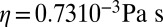 (27). To estimate the latter consistently with Fig. 1A, we follow the convention of the HOLE program, i.e.,
 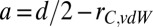 , where d = 0.75 nm is the diameter obtained using the center-to-center distance of carbon atoms, and rC,vdW = 0.17 nm is the carbon van der Waals radius. Eq. 1 then yields a hydrodynamic permeability
 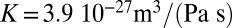 . This suggests that Sampson’s formula gives the correct order of magnitude even at the subnanometric level, down to the single-file regime.
†The permeability pf is defined in the physiology literature from the flux of water Φw (in moles per unit time) resulting from an osmotic pressure difference ΔΠ across the pore, as 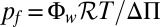 , with ℛ the gas constant (14). It is related to the hydrodynamic permeability K defined as the ratio of the flow rate and pressure drop, as
  , with Vw the molar volume of water.
This article contains supporting information online at www.pnas.org/lookup/suppl/doi:10.1073/pnas.1306447110/-/DCSupplemental.
References
- 1.Borgnia M, Nielsen S, Engel A, Agre P. Cellular and molecular biology of the aquaporin water channels. Annu Rev Biochem. 1999;68:425–458. doi: 10.1146/annurev.biochem.68.1.425. [DOI] [PubMed] [Google Scholar]
- 2.Agre P. Aquaporin water channels (Nobel Lecture) Angew Chem Int Ed Engl. 2004;43(33):4278–4290. doi: 10.1002/anie.200460804. [DOI] [PubMed] [Google Scholar]
- 3.Murata K, et al. Structural determinants of water permeation through aquaporin-1. Nature. 2000;407(6804):599–605. doi: 10.1038/35036519. [DOI] [PubMed] [Google Scholar]
- 4.Sui HX, Han BG, Lee JK, Walian P, Jap BK. Structural basis of water-specific transport through the AQP1 water channel. Nature. 2001;414(6866):872–878. doi: 10.1038/414872a. [DOI] [PubMed] [Google Scholar]
- 5.Rasaiah JC, Garde S, Hummer G. Water in nonpolar confinement: From nanotubes to proteins and beyond. Annu Rev Phys Chem. 2008;59:713–740. doi: 10.1146/annurev.physchem.59.032607.093815. [DOI] [PubMed] [Google Scholar]
- 6.Bocquet L, Charlaix E. Nanofluidics, from bulk to interfaces. Chem Soc Rev. 2010;39(3):1073–1095. doi: 10.1039/b909366b. [DOI] [PubMed] [Google Scholar]
- 7.Majumder M, Chopra N, Andrews R, Hinds BJ. Nanoscale hydrodynamics: Enhanced flow in carbon nanotubes. Nature. 2005;438(7064):44. doi: 10.1038/43844a. [DOI] [PubMed] [Google Scholar]
- 8.Holt JK, et al. Fast mass transport through sub-2-nanometer carbon nanotubes. Science. 2006;312(5776):1034–1037. doi: 10.1126/science.1126298. [DOI] [PubMed] [Google Scholar]
- 9.Siria A, et al. Giant osmotic energy conversion measured in a single transmembrane boron nitride nanotube. Nature. 2013;494(7438):455–458. doi: 10.1038/nature11876. [DOI] [PubMed] [Google Scholar]
- 10.de Groot BL, Grubmüller H. Water permeation across biological membranes: Mechanism and dynamics of aquaporin-1 and GlpF. Science. 2001;294(5550):2353–2357. doi: 10.1126/science.1066115. [DOI] [PubMed] [Google Scholar]
- 11.Jensen MO, Park S, Tajkhorshid E, Schulten K. Energetics of glycerol conduction through aquaglyceroporin GlpF. Proc Natl Acad Sci USA. 2002;99(10):6731–6736. doi: 10.1073/pnas.102649299. [DOI] [PMC free article] [PubMed] [Google Scholar]
- 12.Zhu F, Tajkhorshid E, Schulten K. Theory and simulation of water permeation in aquaporin-1. Biophys J. 2004;86(1 Pt 1):50–57. doi: 10.1016/S0006-3495(04)74082-5. [DOI] [PMC free article] [PubMed] [Google Scholar]
- 13.Ho JD, et al. Crystal structure of human aquaporin 4 at 1.8 A and its mechanism of conductance. Proc Natl Acad Sci USA. 2009;106(18):7437–7442. doi: 10.1073/pnas.0902725106. [DOI] [PMC free article] [PubMed] [Google Scholar]
- 14.Finkelstein A, Andersen OS. The gramicidin A channel: A review of its permeability characteristics with special reference to the single-file aspect of transport. J Membr Biol. 1981;59(3):155–171. doi: 10.1007/BF01875422. [DOI] [PubMed] [Google Scholar]
- 15.Thomas JA, McGaughey AJH. Water flow in carbon nanotubes: Transition to subcontinuum transport. Phys Rev Lett. 2009;102(18):184502. doi: 10.1103/PhysRevLett.102.184502. [DOI] [PubMed] [Google Scholar]
- 16.Sampson RA. On Stokes’s current function. Philosophical Transactions of the Royal Society A: Mathematical, Physical and Engineering Sciences. 1891;182:449–518. [Google Scholar]
- 17.Weissberg HL. End correction for slow viscous flow through long tubes. Phys Fluids. 1962;5(9):1033. [Google Scholar]
- 18.Dagan Z, Weinbaum S, Pfeffer R. An infinite-series solution for the creeping motion through an orifice of finite length. J Fluid Mech. 1982;115:505–523. [Google Scholar]
- 19.Hummer G, Rasaiah JC, Noworyta JP. Water conduction through the hydrophobic channel of a carbon nanotube. Nature. 2001;414(6860):188–190. doi: 10.1038/35102535. [DOI] [PubMed] [Google Scholar]
- 20.Falk K, Sedlmeier F, Joly L, Netz RR, Bocquet L. Molecular origin of fast water transport in carbon nanotube membranes: Superlubricity versus curvature dependent friction. Nano Lett. 2010;10(10):4067–4073. doi: 10.1021/nl1021046. [DOI] [PubMed] [Google Scholar]
- 21.Sisan TB, Lichter S. The end of nanochannels. Microfluid Nanofluid. 2011;11:787–791. [Google Scholar]
- 22.Nicholls WD, Borg MK, Lockerby DA, Reese JM. Water transport through (7,7) carbon nanotubes of different lengths using molecular dynamics. Microfluid Nanofluid. 2011;12(1-4):257–264. [Google Scholar]
- 23. Walther JH, Ritos K, Cruz-Chu E, Megaridis CM, Koumoutsakos P (2013) Barriers to superfast water transport in carbon nanotube membranes, Nano Lett 13(5):1910–1914. [DOI] [PubMed]
- 24.Joly L. Capillary filling with giant liquid/solid slip: Dynamics of water uptake by carbon nanotubes. J Chem Phys. 2011;135(21):214705. doi: 10.1063/1.3664622. [DOI] [PubMed] [Google Scholar]
- 25.Hashido M, Kidera A, Ikeguchi M. Water transport in aquaporins: Osmotic permeability matrix analysis of molecular dynamics simulations. Biophys J. 2007;93(2):373–385. doi: 10.1529/biophysj.106.101170. [DOI] [PMC free article] [PubMed] [Google Scholar]
- 26.Suk M, Aluru N. Water transport through ultrathin graphene. J Phys Chem Lett. 2010;1(10):1590. [Google Scholar]
- 27.González MA, Abascal JL. The shear viscosity of rigid water models. J Chem Phys. 2010;132(9):096101. doi: 10.1063/1.3330544. [DOI] [PubMed] [Google Scholar]
- 28.Bernstein FC, et al. The Protein Data Bank: A computer-based archival file for macromolecular structures. J Mol Biol. 1977;112(3):535–542. doi: 10.1016/s0022-2836(77)80200-3. [DOI] [PubMed] [Google Scholar]
- 29.Smart OS, Neduvelil JG, Wang X, Wallace BA, Sansom MSP. HOLE: A program for the analysis of the pore dimensions of ion channel structural models. J Mol Graph. 1996;14(6):354–360, 376. doi: 10.1016/s0263-7855(97)00009-x. [DOI] [PubMed] [Google Scholar]
- 30.Bocquet L, Barrat J-L. Flow boundary conditions from nano- to micro-scales. Soft Matter. 2007;3(6):685–693. doi: 10.1039/b616490k. [DOI] [PubMed] [Google Scholar]
- 31.Cui Y, Bastien DA. Water transport in human aquaporin-4: molecular dynamics (MD) simulations. Biochem Biophys Res Commun. 2011;412(4):654–659. doi: 10.1016/j.bbrc.2011.08.019. [DOI] [PMC free article] [PubMed] [Google Scholar]
- 32.de Groot BL, Engel A, Grubmüller H. The structure of the aquaporin-1 water channel: A comparison between cryo-electron microscopy and X-ray crystallography. J Mol Biol. 2003;325(3):485–493. doi: 10.1016/s0022-2836(02)01233-0. [DOI] [PubMed] [Google Scholar]
- 33.Harries WEC, Akhavan D, Miercke LJ, Khademi S, Stroud RM. The channel architecture of aquaporin 0 at a 2.2-A resolution. Proc Natl Acad Sci USA. 2004;101(39):14045–14050. doi: 10.1073/pnas.0405274101. [DOI] [PMC free article] [PubMed] [Google Scholar]
- 34.Zhang YB, Chen LY. In silico study of Aquaporin V: Effects and affinity of the central pore-occluding lipid. Biophys Chem. 2013;171:24–30. doi: 10.1016/j.bpc.2012.09.004. [DOI] [PMC free article] [PubMed] [Google Scholar]
- 35.Jensen MØ, Mouritsen OG. Single-channel water permeabilities of Escherichia coli aquaporins AqpZ and GlpF. Biophys J. 2006;90(7):2270–2284. doi: 10.1529/biophysj.105.073965. [DOI] [PMC free article] [PubMed] [Google Scholar]
- 36.Fischer G, et al. Crystal structure of a yeast aquaporin at 1.15 angstrom reveals a novel gating mechanism. PLoS Biol. 2009;7(6):e1000130. doi: 10.1371/journal.pbio.1000130. [DOI] [PMC free article] [PubMed] [Google Scholar]
Associated Data
This section collects any data citations, data availability statements, or supplementary materials included in this article.